
Preface: I had written a good chunk of this article last year, but decided to roll the high level overview into “Change Of Plan” as it explained a lot of why the overall project evolved the way that it did. But seeing as this project was incredibly labor intensive and had many facets, it deserves it’s own stage.
During my time driving cars hard, I’ve become a little bit spoiled by motorsport-grade dampers. I’ve been fortunate enough to own two different sets of Xidas (NA and SE3P), which are made by Tractive, and a set of AST 5200 double adjustable, with external reservoirs also on my RX-8.
As soon as I purchased my S13, I knew that it needed something of the same nature. While the 20+ year old Stance GR+s have performed shockingly well, I definitely wanted more performance and adjustment. While I would love to just pony up the cash and buy MCS 2WRs straight away, I know that I should get some more seat time in the car before yarding that much money into dampers. While it turns out I love the car to death and have every intention to keep it around, I still don’t think it is the right fit for the car (for now, definitely leaving that door open in the future).
After looking around at what was available, I was pretty underwhelmed. For being a chassis that is well loved for competition use, the “real” damper options were next to nonexistent. The most enticing option was either Feal or Stance as I have heard good things about both of them, but neither of them felt right for the application. Not enough for me to dump over $2000 into either ecosystem. Shaftworks was in the discussion, but for around $3000, I can figure out how to justify MCS 1WNRs for just a bit more.
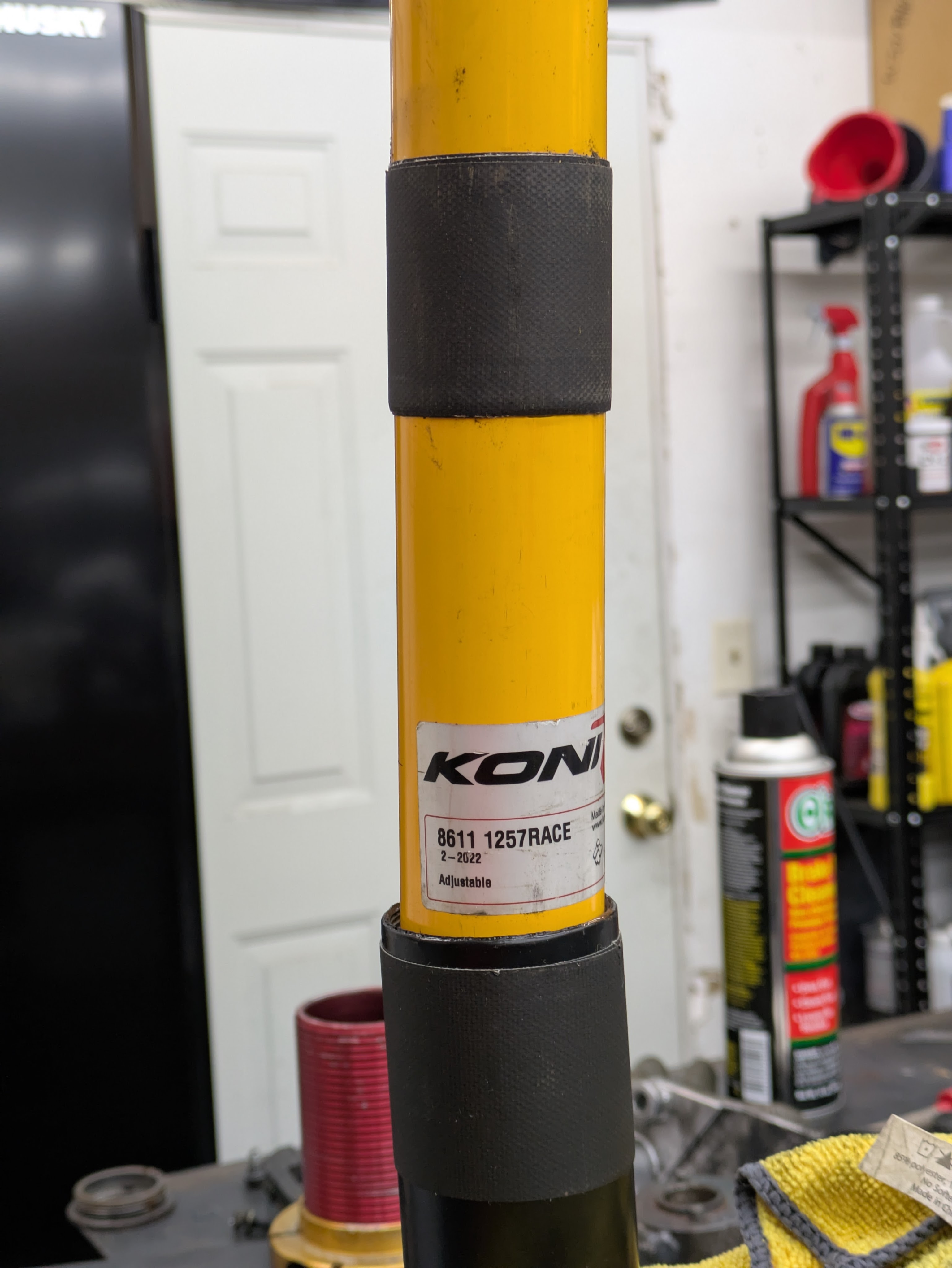
What I really wanted was the gold standard of the Nissan Road Racing forum, lovingly referred to as 8611s. It is a cartridge style coilover system based around the Koni 8611-1259RACE monotube strut insert. The dampers, while not application specific, have a good valving curve for the spring rates the chassis likes, and are independently compression and rebound adjustable. While it is no longer as financially compelling as it used to be at over $400 per insert, its still a well tested setup that has put plenty before me on the top of the box.
The barrier to entry to 8611s in 2026 are the housings. These were made by a few parties, the most notable being Richard, screenname Veilside180SX and primarily sold on NRR. Unfortunately, the last recorded production was roughly 2013. While plenty of people had them back in the day, their niche market segment back then has made them nearly impossible to find now. I had written off the possibility of running a set due to rarity, but then I got lucky.
My good friend Alex, who raced S13s for decades and maintains NRR to this day, used his connections and was able to track me down a set of housings via a gentleman named Denis in Pennsylvania. He had switched to JRZ RS-PROs recently and was willing to pass along his Koni parts. While not the exact setup that I wanted, as it had 8610s in the rear (same damper, just single adjustable rather than double), it got me really close.
The second set of housings came from another local retired S chassis racer Garrett. He had a huge bin of assorted parts, and in it was a pair of front housings for Konis. I ended up purchasing the big box of random stuff which has furnished many of the engine spares that I currently own.
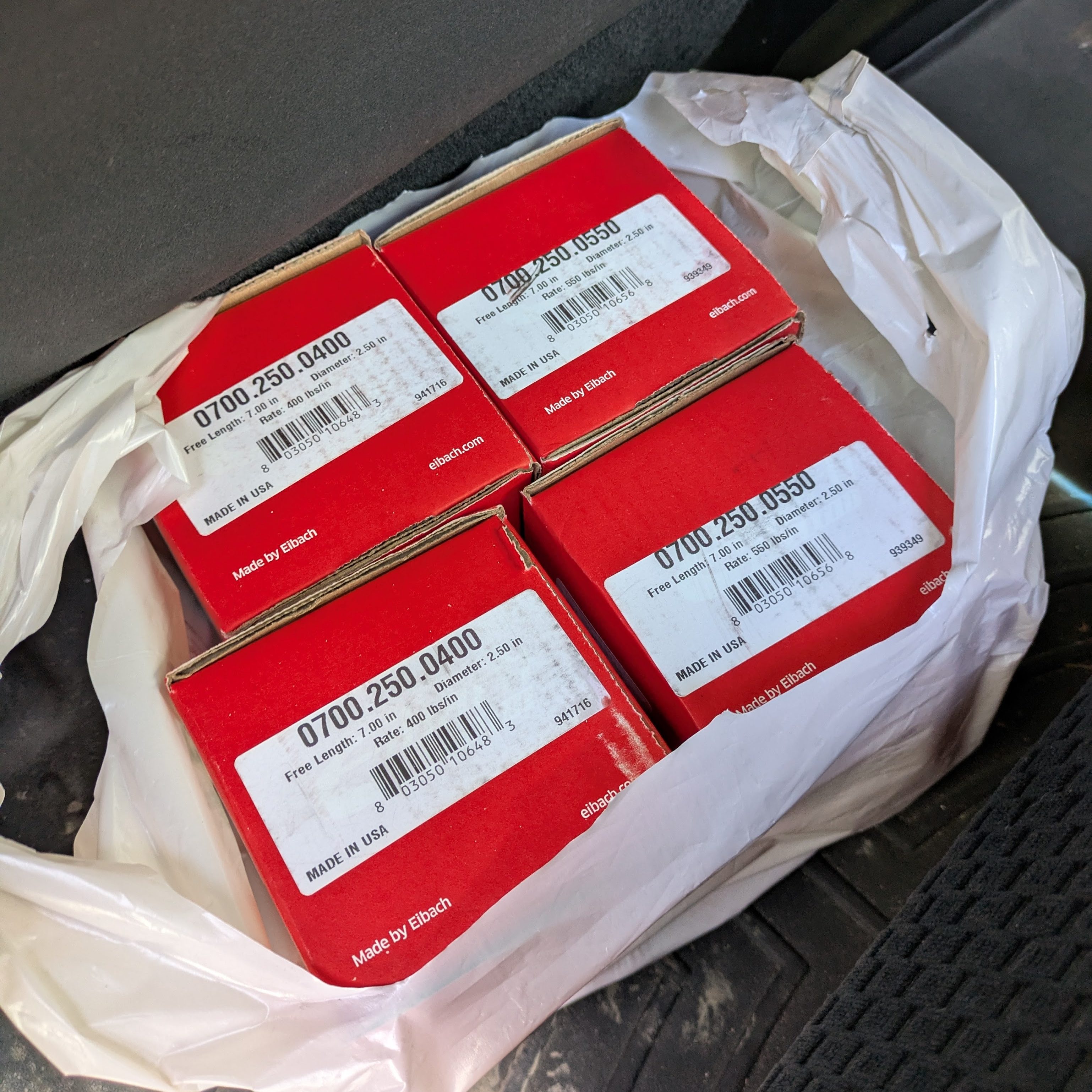
In continuing the parts search, and by some blind stroke of luck, someone had the correct length/diameter/rate springs, brand new in box, on Marketplace. Nice to save a few bucks.
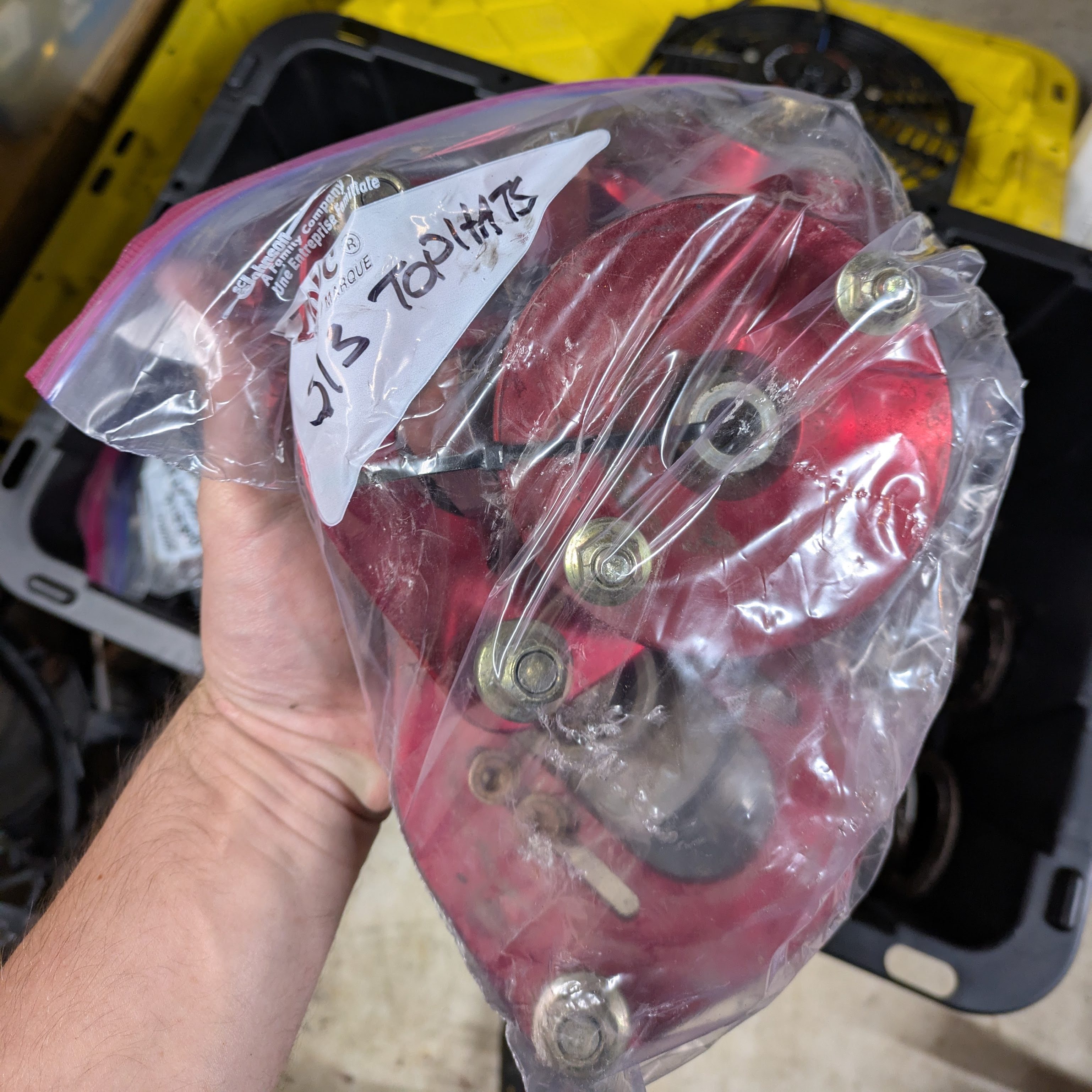
The last large piece of the equation that I was missing was rear top hats. Denis had reused his with his JRZs, and I was planning to buy some Tein ones off eBay and modify them to my needs. However, for whatever insane reason, 5 years ago I had decided to keep some Megan S13 tophats that my college roommate Aidan had on his S13 coupe. We were going to throw those coilovers away since they were seized and blown, however I gutted them of any usable part and hoarded them away. I remembered one day that I had these and knew exactly where they were.
With all the parts gathered, it was time to assemble it all together right? Oh how I wish is that simple. This kicks off what would eventually turn into months working lunches and evenings in the machine shop to get it all to play nice.
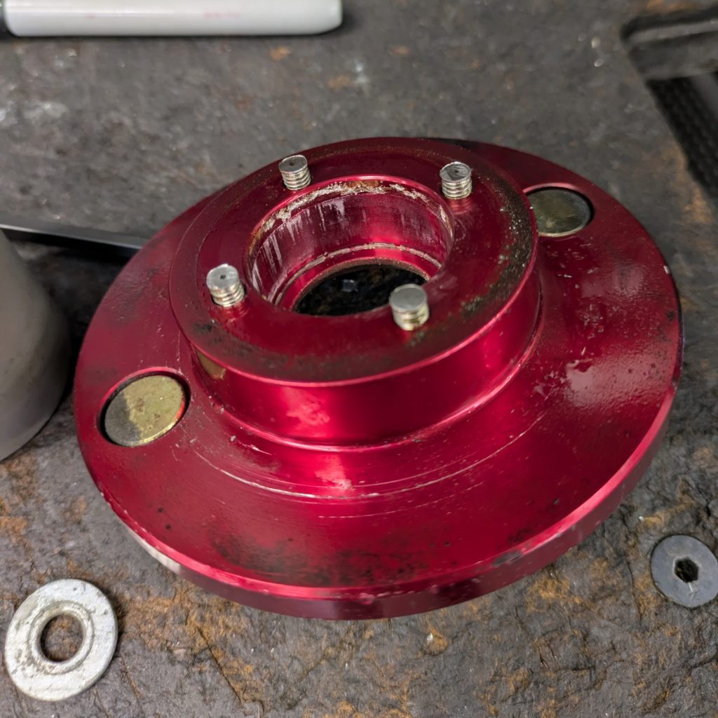
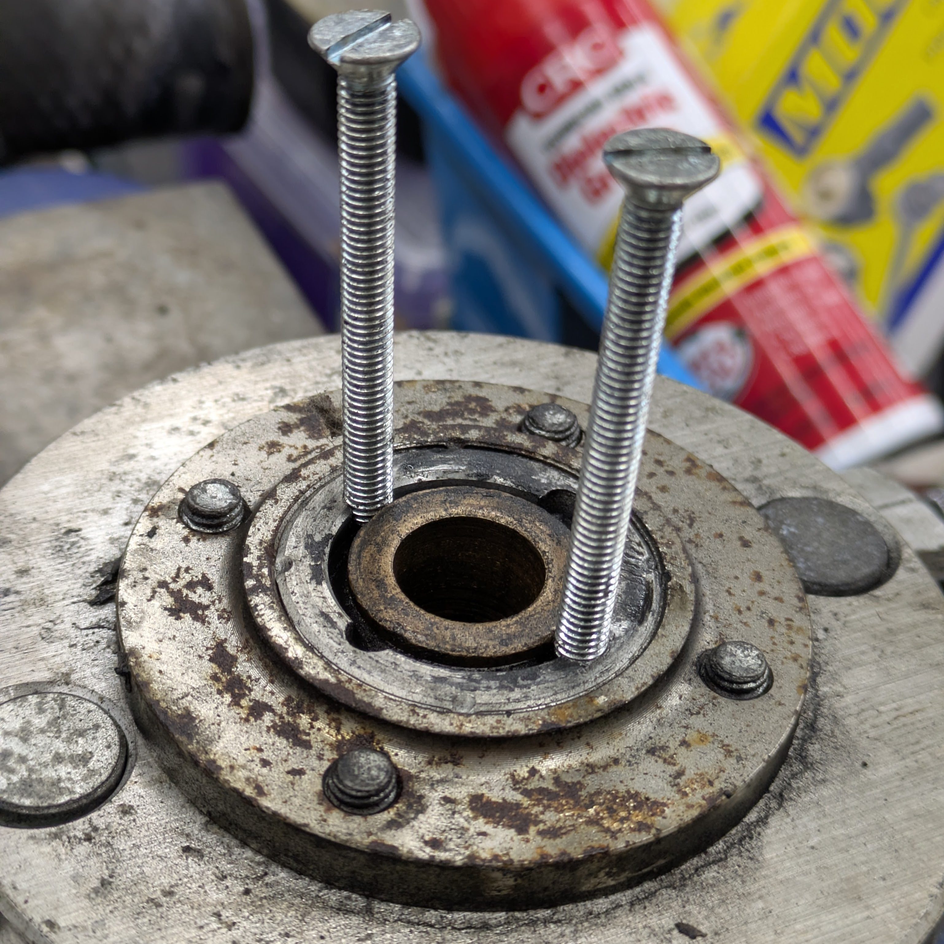
In an attempt to bring the Megan hardware up to reasonable standards, I figured it would be a good idea to replace all of the bearings and hardware associated with the plates, as the rear coaxial bearings were completely seized. After rounding out basically all of the completely corroded Button Head Cap Screws that hold the bearing retention plate on, the plates ventured to work to undergo disassembly and redesign.
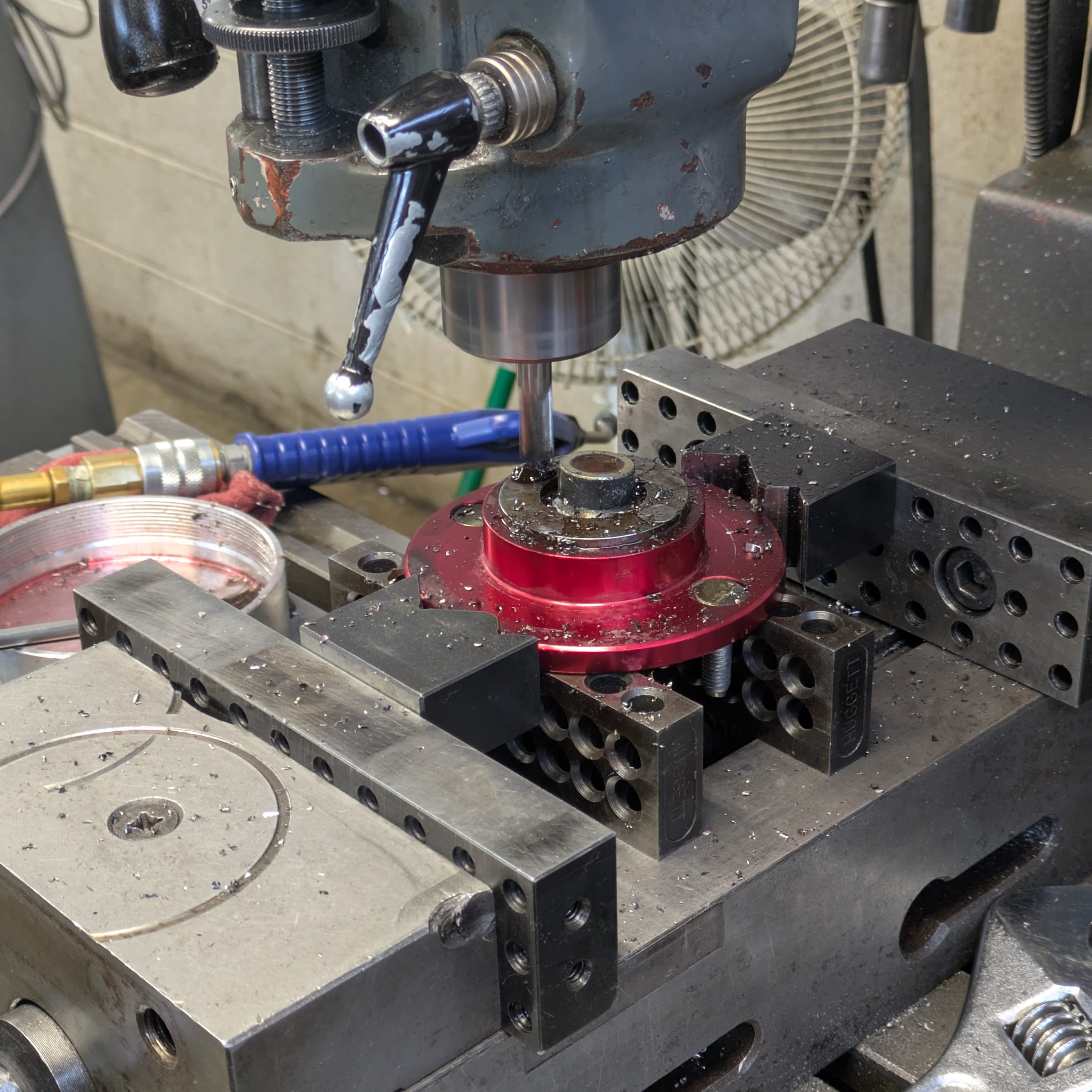
Step number 1 was just getting the components into a useable state. After evaluating my options, I decided to just mill the heads of the screws off, take the bearing retention plate off, and remove the remainder of the BHCSs with vice grips. Once the heads were decked, I moved to the press and sheared the remainder of the heads off of the bolts into adorable little washers.
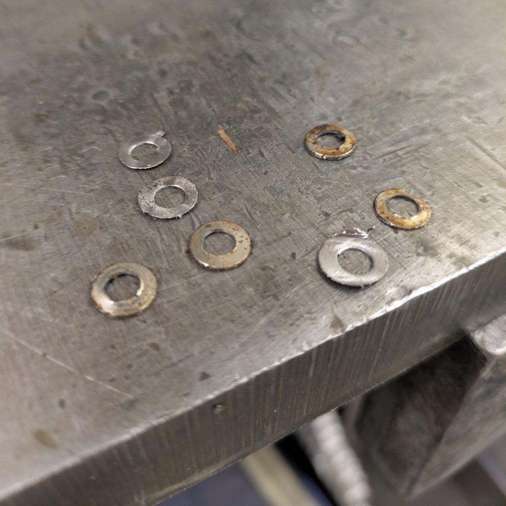
Once the retainer plate was removed and the threads exposed, the screws came out without a fight. I pressed the studs out, and was left with a “stripped” rear top hat.
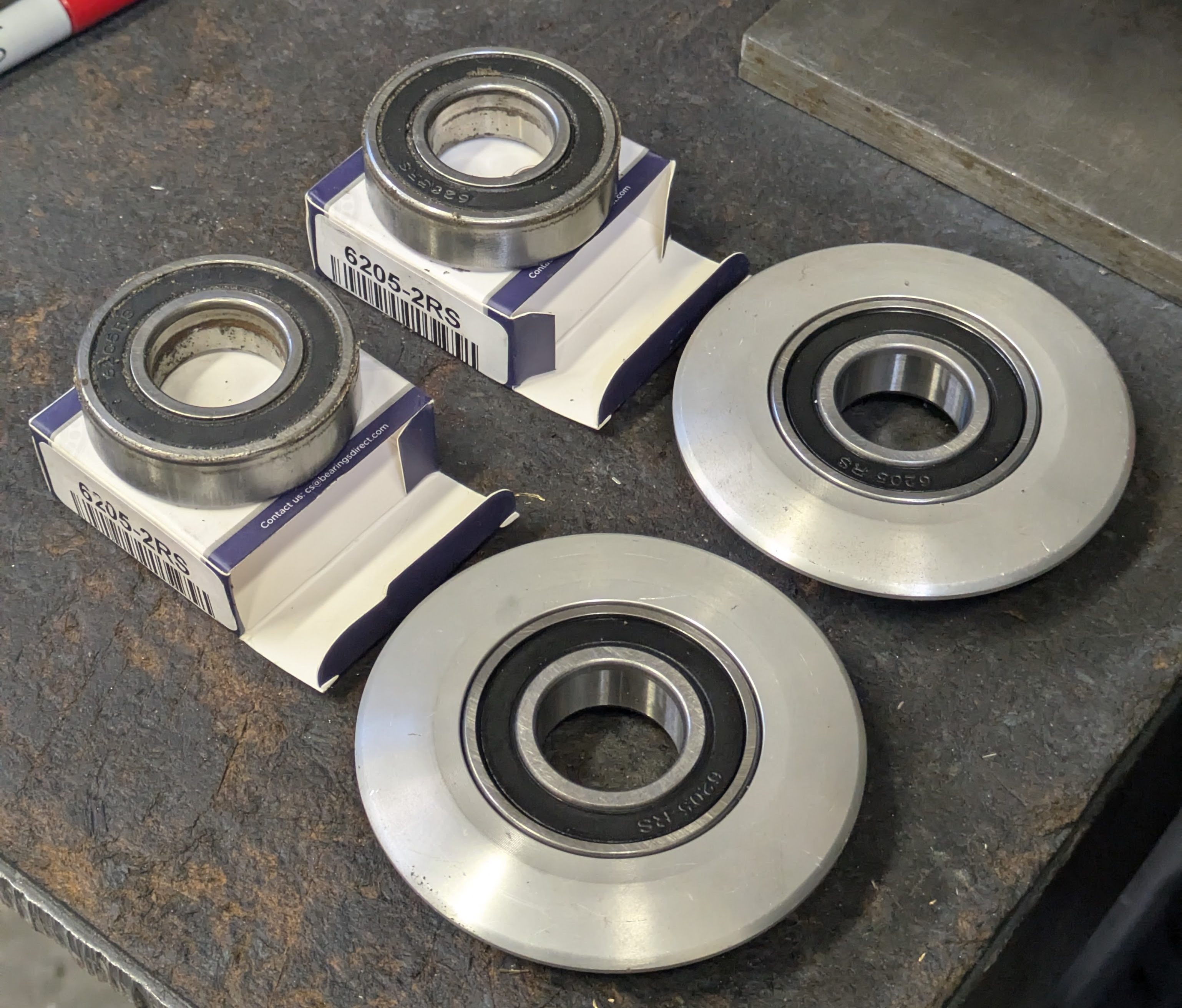
Other than just replacing the bearings, my goal here was to lower the consumables cost if possible. One of the downsides of China coilovers is the use of weird size metric bearings, which are usually far more expensive than their imperial counterparts. In this case, the 33mm OD, 16mm ID spherical bearing was identical to what Ohlins uses in some of their tophats, and while available, the $100/each for a PTFE lined monoball was a little steep for something that is a consumable. For reference, a COM or AIN imperial bearing of an equivalent size is anywhere between $12-18 from FK or Aurora. I did find what all of the cheap coilovers come with after a quick search on AliExpress for a few bucks per piece, however plain/non PTFE bearings are going to seize immediately in an automotive application, so that was out of the question.
As custom misalignment spacers were already required to adapt to Konis, I figured why not take it a step further and update the tophats to imperial bearings for both economic and procurement benefits. I found a FK AIN-10T with a 1-5/16″ OD that will require minimal over-boring (0.0125″) and decking (for bearing thickness) on the top hats and drops the price per bearing down to $20 for a high quality bearing that I can get stateside. Win.
So for the rear: Megan tophats, bored and decked for AIN-10T bearings, new hardware for the bearing retainer plate, custom misalignment spacers for the Konis, and Torrington bearing for the springs for reduction of binding.
The front felt more daunting initially as I got all caught up on the idea of cool custom stuff, but you’ll see in a minute why I brought it back around to simple.
Caster adjustment on Macpherson strut suspension can be done in two ways: either from a caster arm, or the tophat. Due to the typical design of most Macpherson tophats, including the OG T3 tophats I got with my 8611 stuff, means that the studs end up becoming nuts and bolts in slots if you want caster adjustment, which is a galactic pain in the ass to actually use. Frankly I just wasn’t happy with the solution, but I wanted caster adjustment independent of the LCA, so I had to make my own tophat.
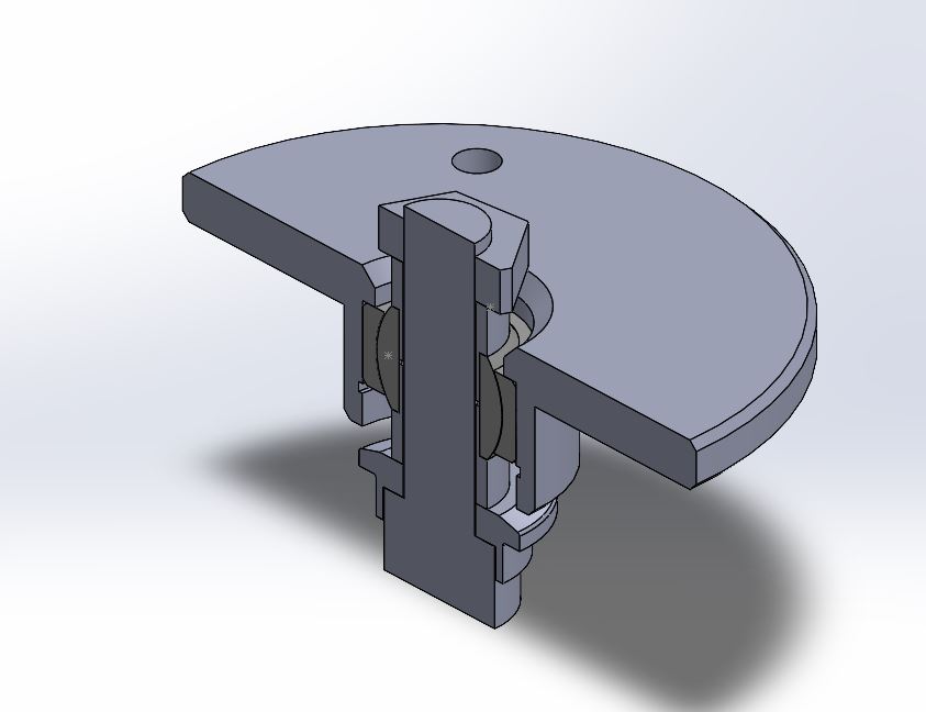
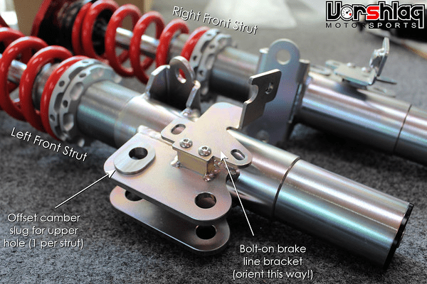
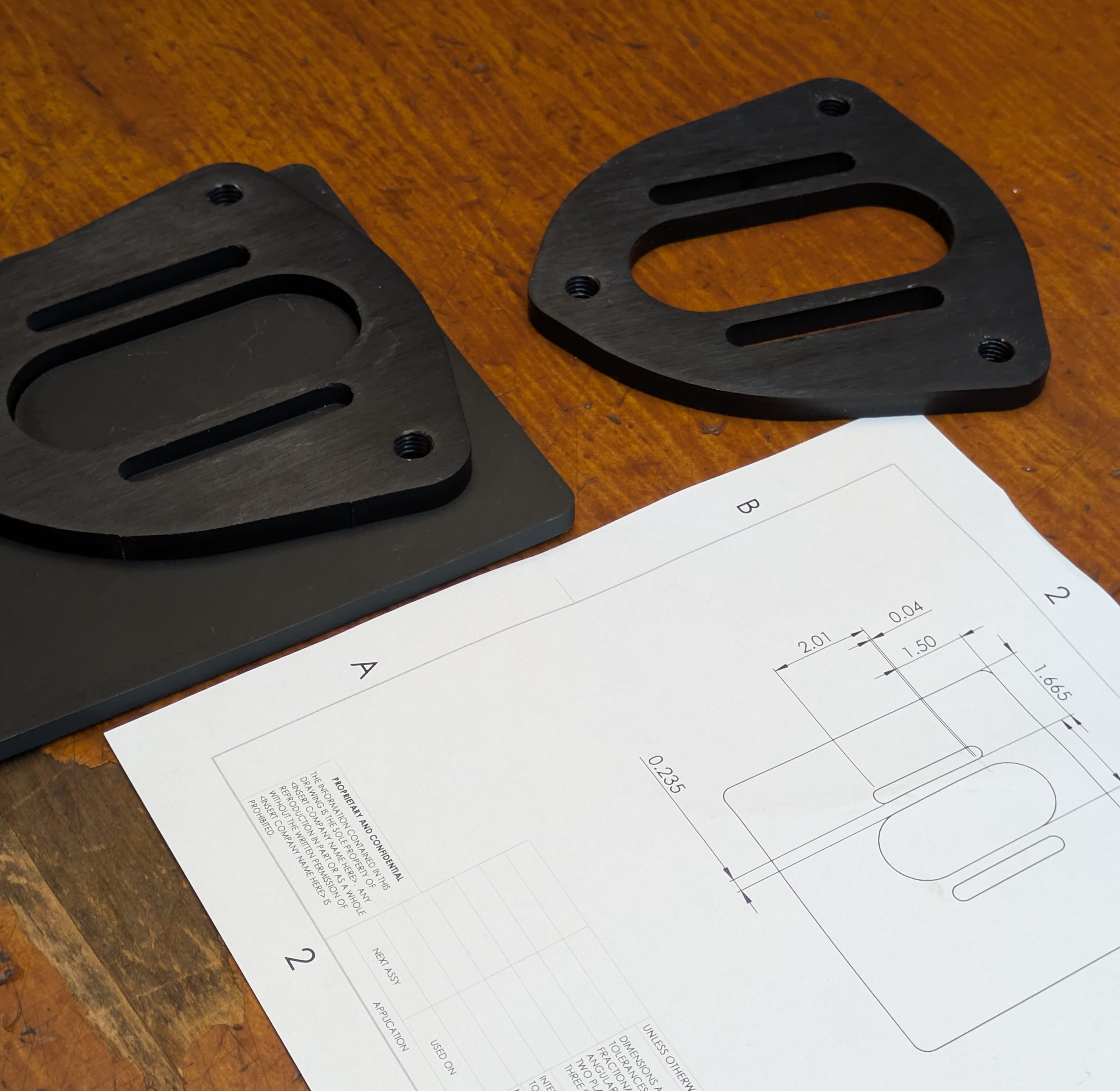
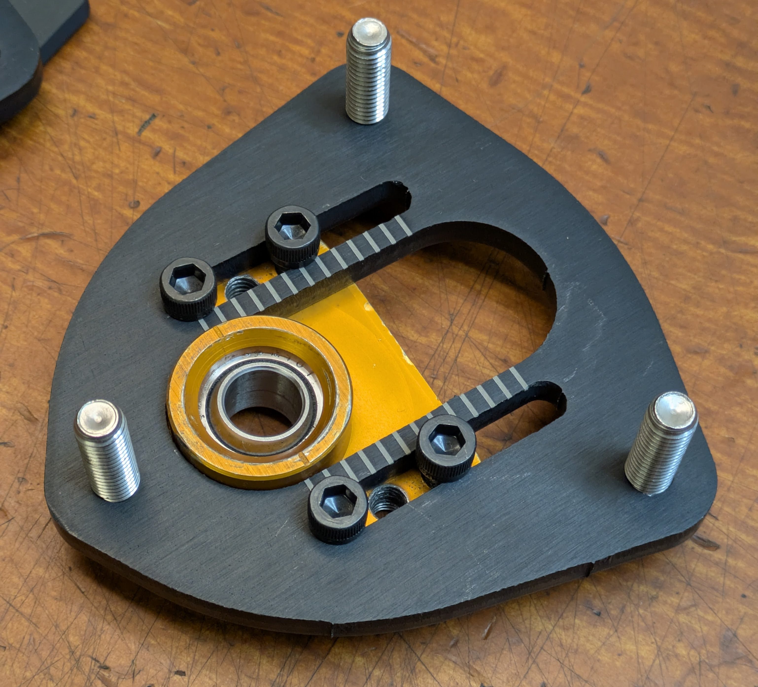
This starts by mimicking an excellent piece of design from the now defuncted Raceseng. The FT86 community will be familiar with their CASCAM tophats as the ultimate solution to this problem, shown below:
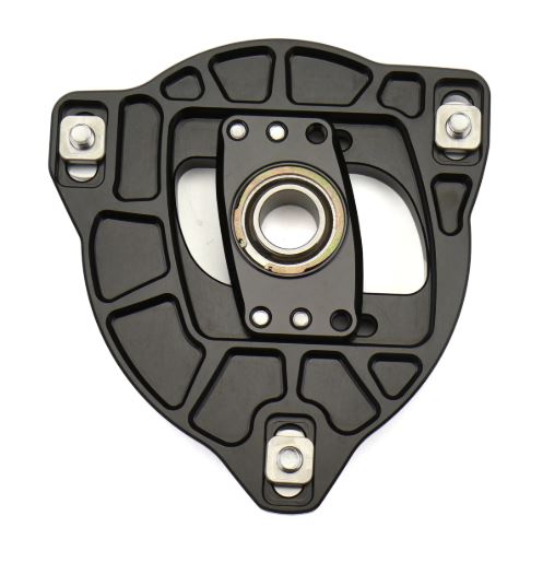
When viewed from the bottom here, you can see Raceseng’s solution for the caster issue. They used square nuts with retaining tunnels in a 1 piece billet camber plate. I’ve seen a few sets in person, they are truly lovely, but I wanted to take it a step further, because the square nuts can still fall out in this case.
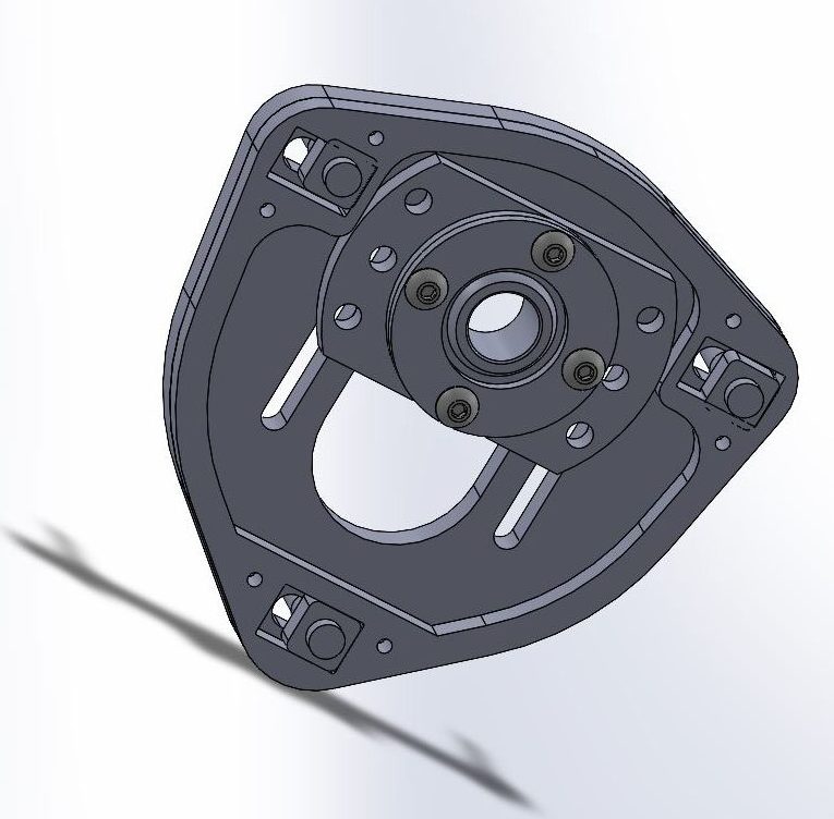
I went so far as to completely draw up my own S13 CASCAM system in CAD that used only laser cut sheet metal, 3D printing, and McMaster/Bellmetric hardware. While I had a blast doing it, I sat with the idea a bit longer and decided that it would be more annoying than helpful. Even if all the hardware was captive, it would still suck to adjust, and it overall has pretty meaningless adjustment in the grand scheme of things. FT86s need that adjustment as they don’t have adjustable caster without an aftermarket LCA, and the tension rod geometry on S13s is totally adequate. With the inclusion of an aftermarket tension arm, I’ll have plenty of adjustment, so fixed tophats it was.
I decided to just use the Megan tophats for all 4 corners, and make the same round of updates to the rear as I am to the front.
This was all fine and dandy, until Luis’s 8611s became mine. I talked about that deal extensively in the “Change of Plan” post.
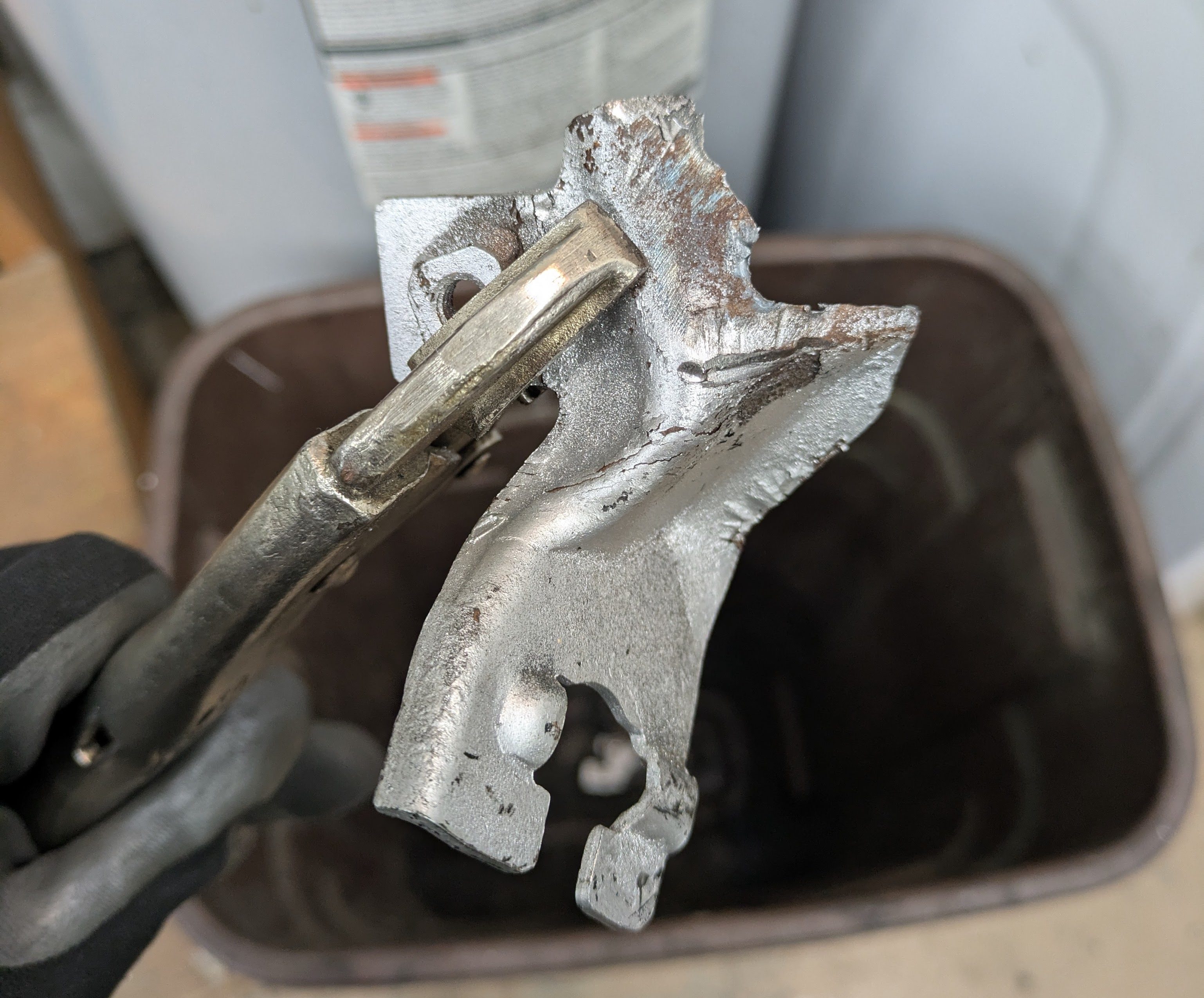
After spending an evening tearing down Luis’s setup, there was zero hope of reusing the tophats. They used the same terrible bearing size as the Megans did, but with an even less serviceable bearing retention style and dreadful build quality.
These use steel bearing housings with an aluminum fine thread retention ring. While not being difficult to remove (would be easier if I had the right pin drive tool), the fine threads and butter soft aluminum means that all four of them pretty much destroyed themselves upon disassembly. You couldn’t pay me to use these, so those were out.
This left me in a tough spot. At this point, my plan was to use most of what Luis had (housings, dampers, sleeves, radial perches) and add my Megan tophats and springs that I had picked up. This would leave me with pretty much everything to make another set of dampers, so I figured I could sell those off to help stomach some of the expense of buying an unexpected set of coilovers.
I attempted for a short while to sell my leftover pile of parts, which didn’t end up happening as you’ll see in a minute. This led to being able to make a second, entirely complete set of dampers with my leftover parts as I was able to modify my already modified housings and leave Luis’s untouched.
At this point, it became clear that if I was gong to leave the untouched Veilside housings alone, there were no off-the-shelf parts that suited my needs, and that I was much better off just ripping off the Band-Aid and custom making everything I needed.
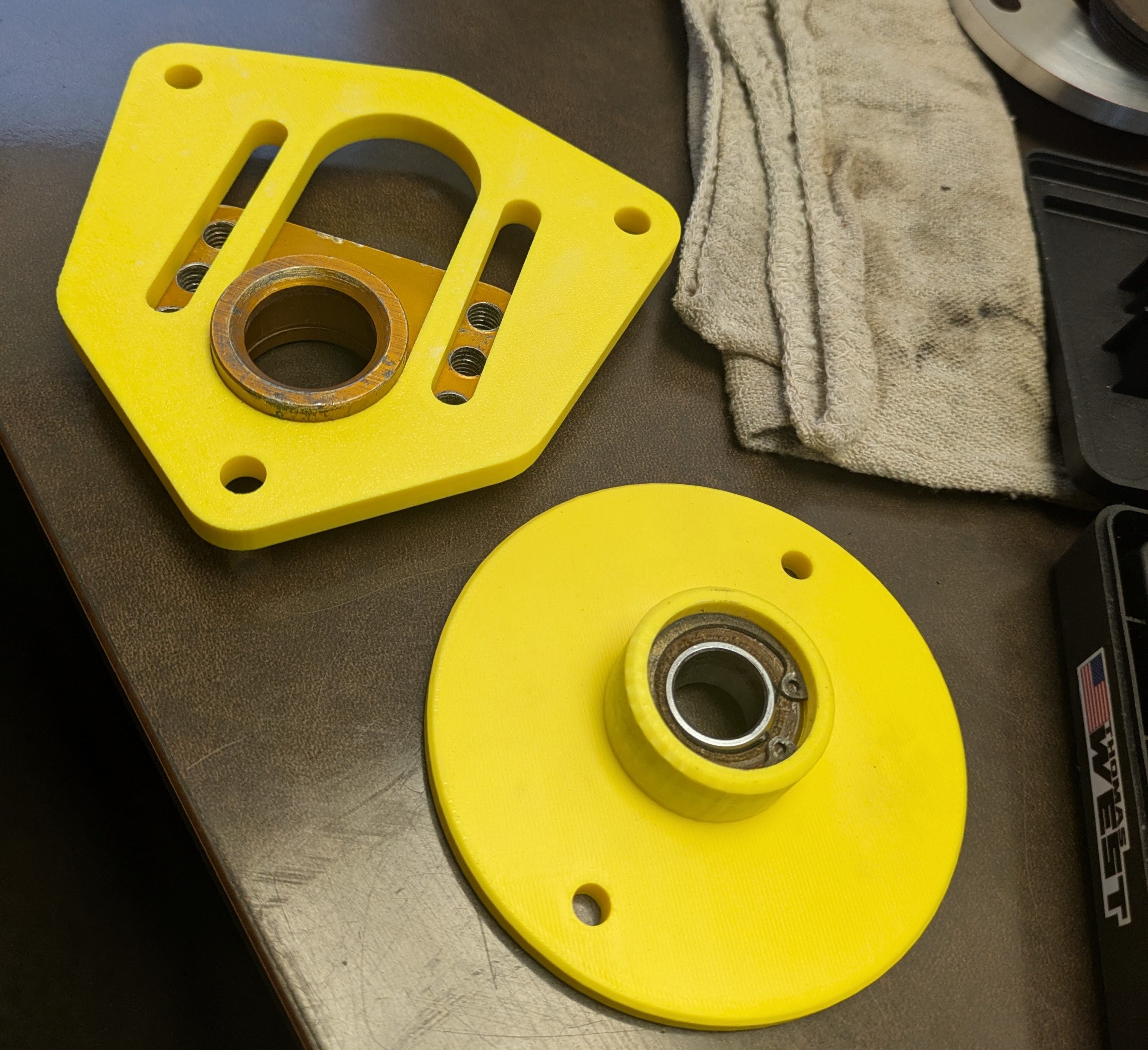
I began with 3D printed mockups to verify dimensions and fitment before committing to the metal variants. The front is the effective shape of the T3 tophats without the provisions to change caster, and the rear is of my own design with the bearing geometry of the T3s and general dimensions of the Megans. Both of these fit great, so it was time to turn them into metal. The front tophat plates were incredibly simple as they were an easy SendCutSend flat part, but the rear being a custom machined part was going to take some work.
Knowing how setup critical the rear was going to be, and the significant time investment required to pull off a pair of successful parts, I knew this was a weekend job in the machine shop. I was able to convince some coworkers to come in as we have a safety policy related to minimum number of staff in the shop, and we had our first “Hobby Day” as I called it. Fortunately it wasn’t just me, a few other people came in to make parts of their own. The only downside is I was getting absolutely thrashed by a cold, so I was powering through with plenty of orange juice and tissues, and luckily my father was there as I was running short on brain cells.
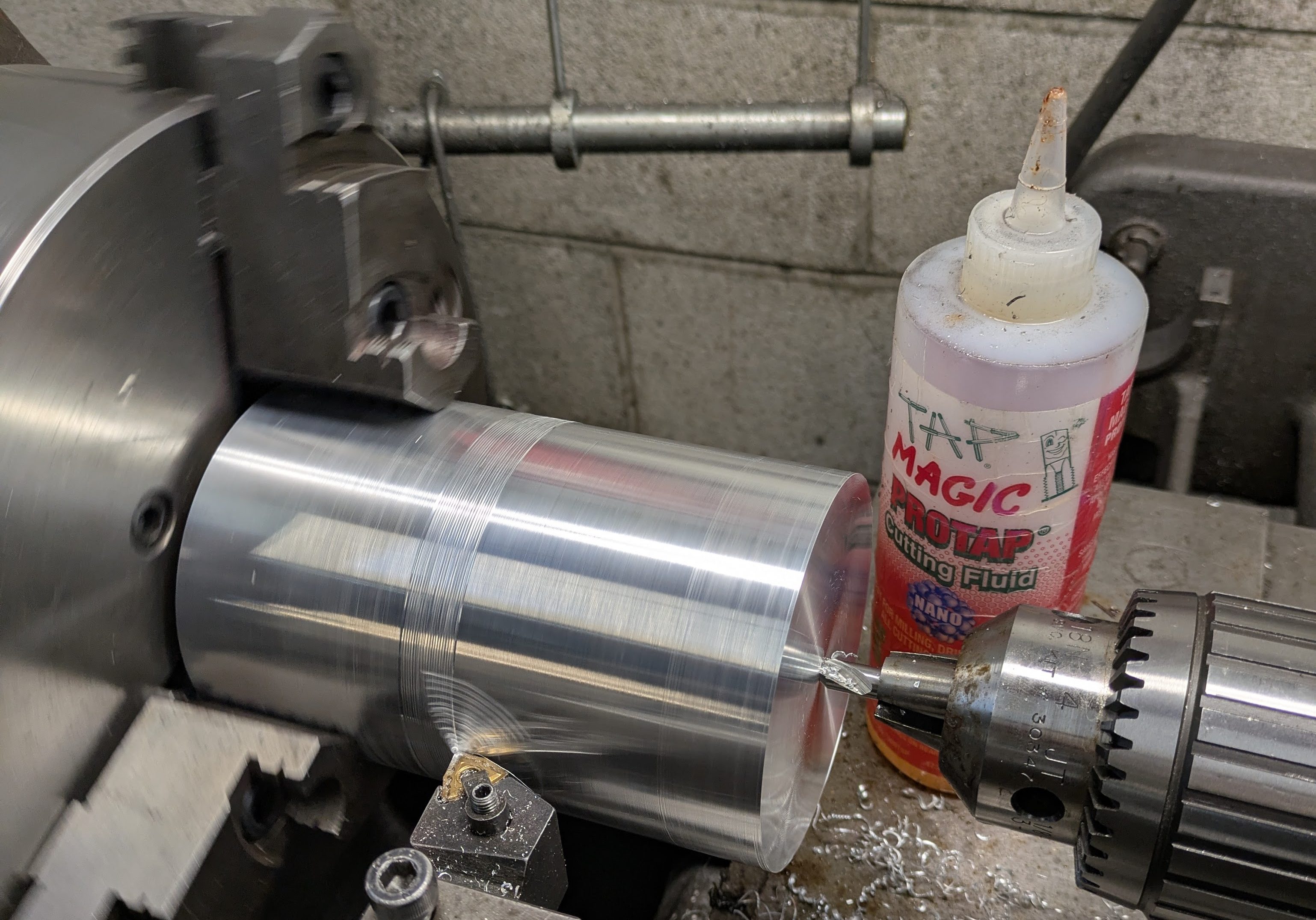
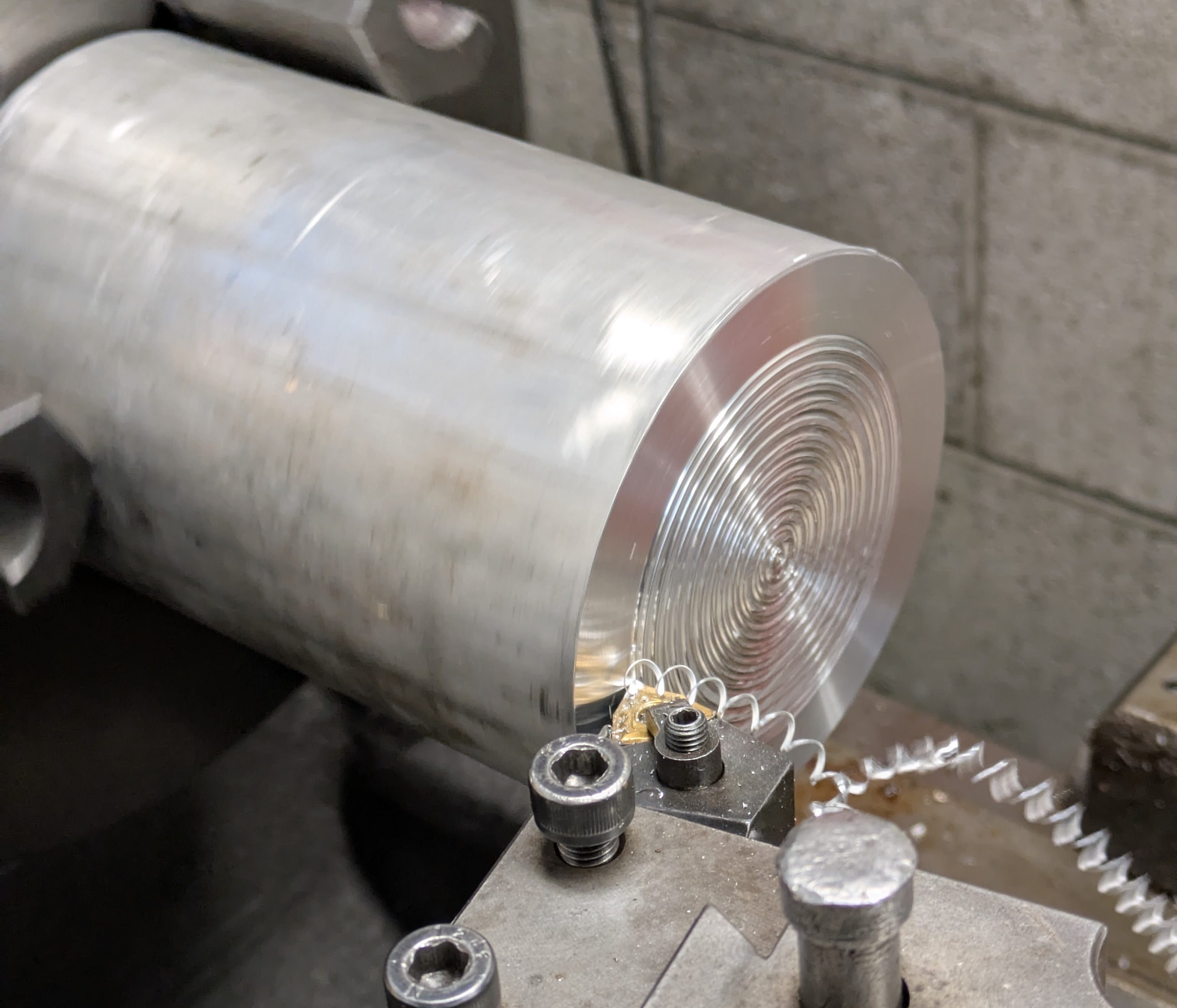
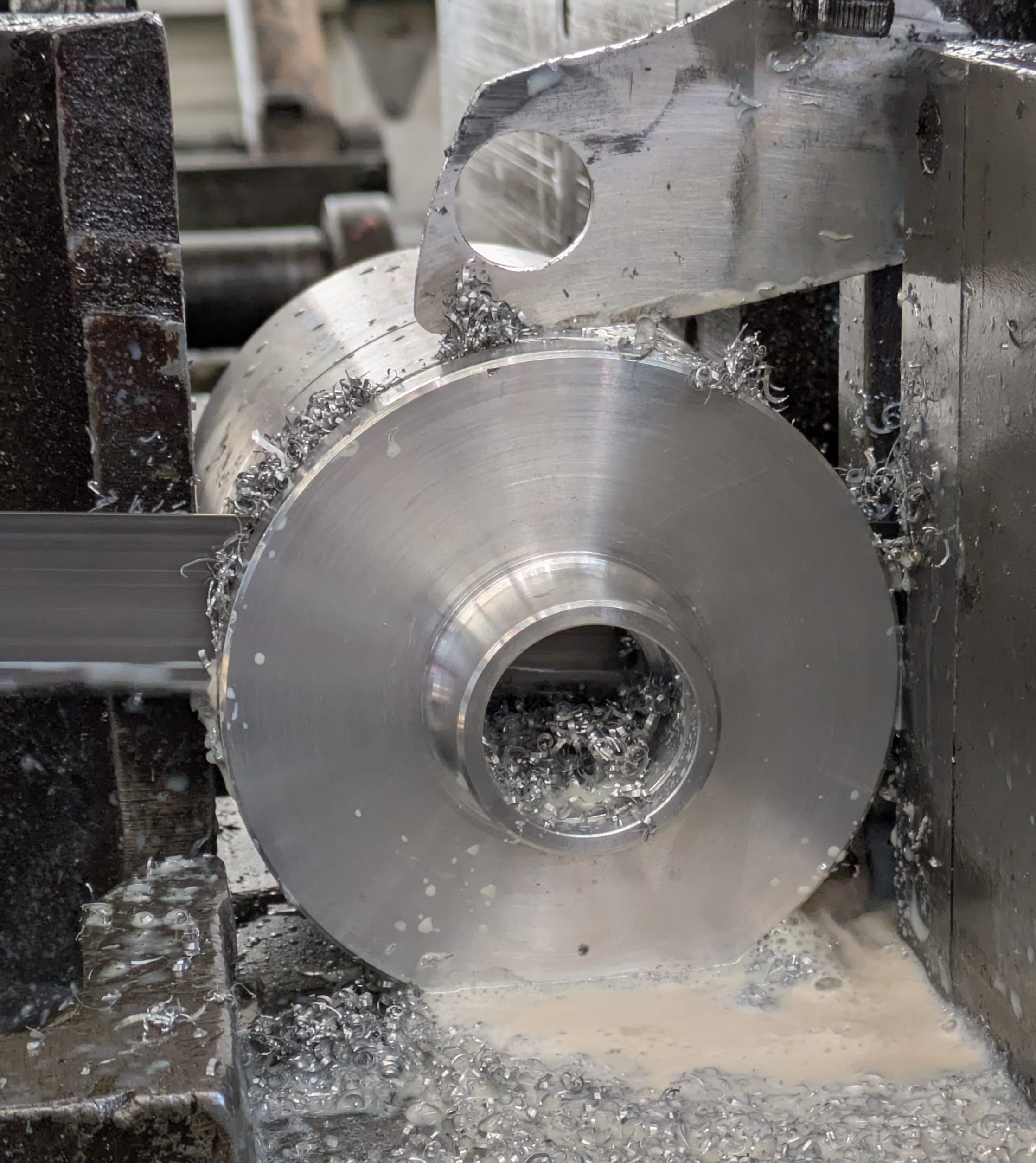
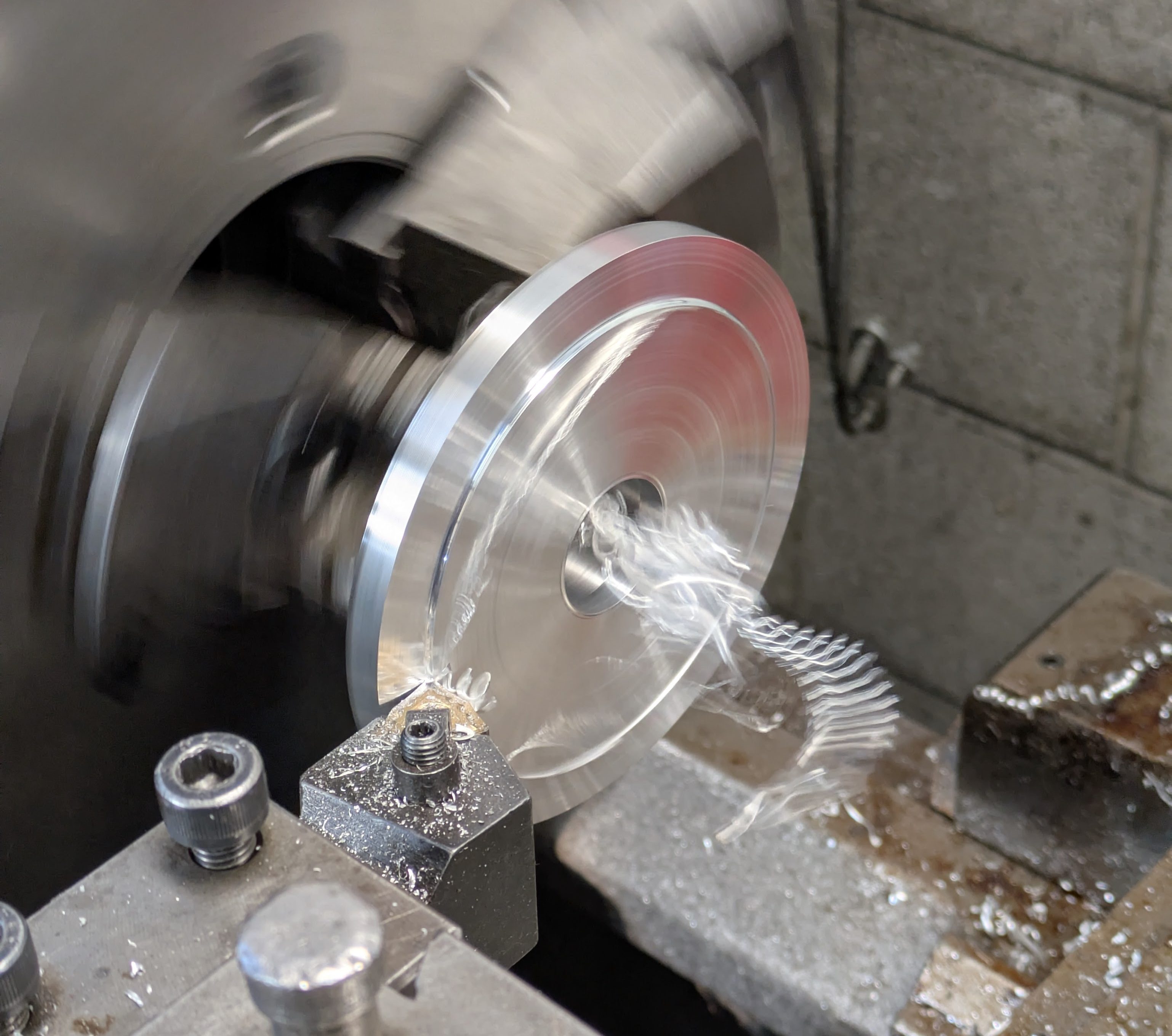
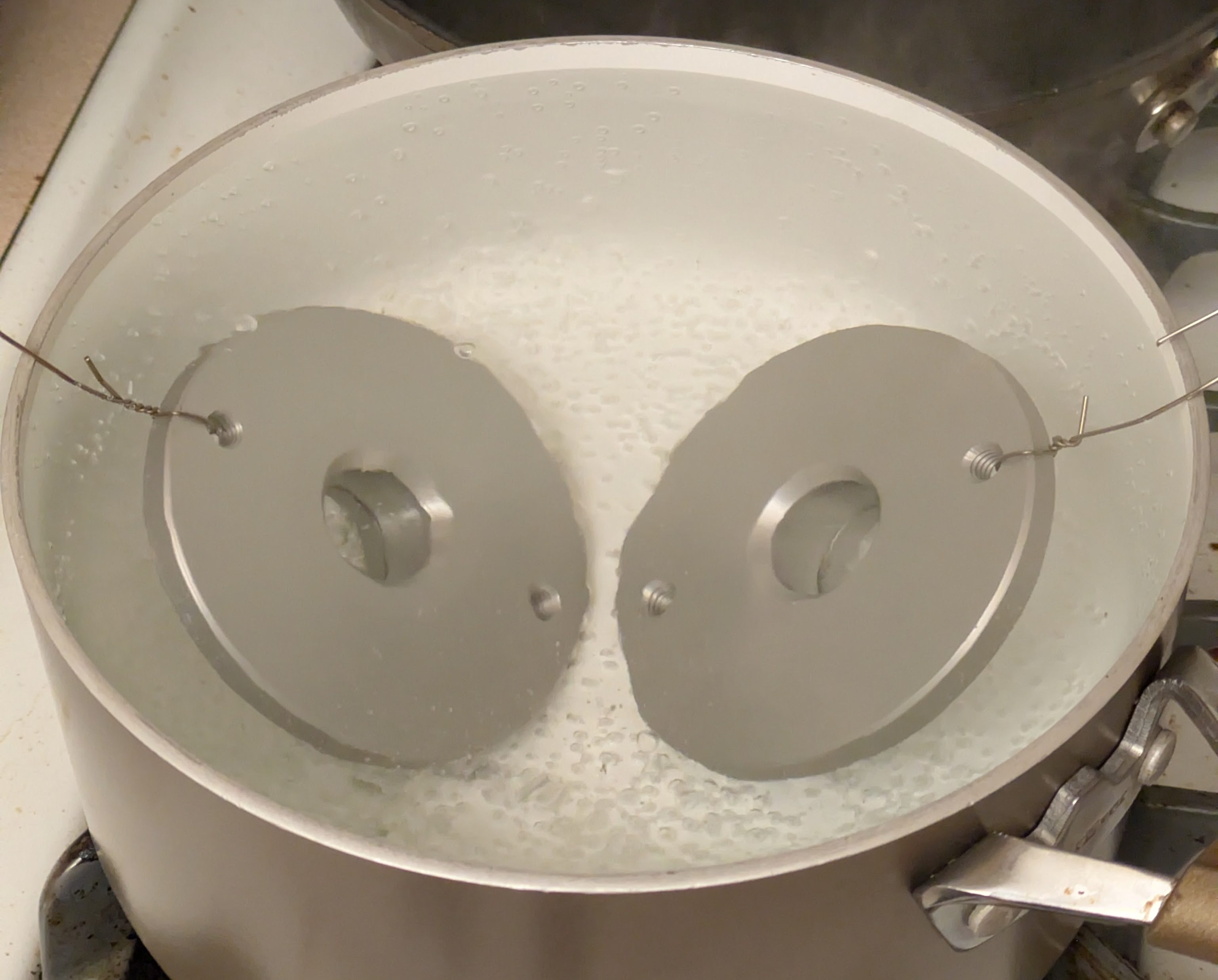
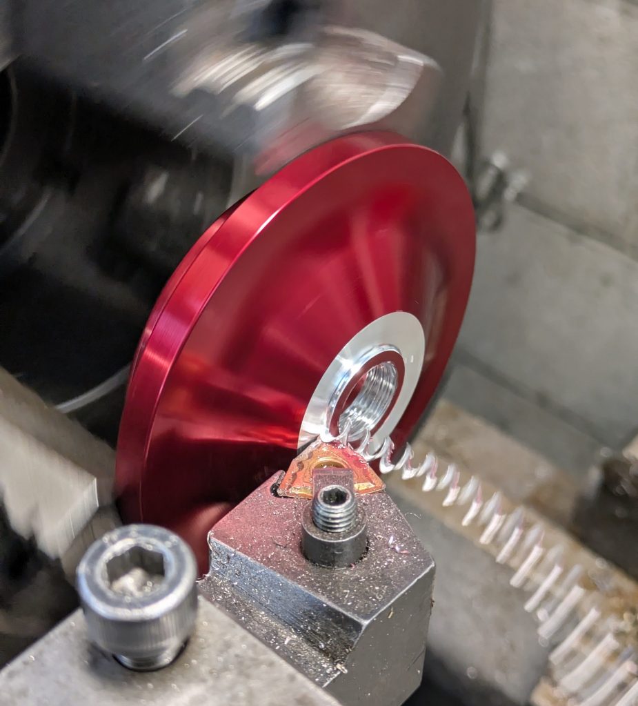
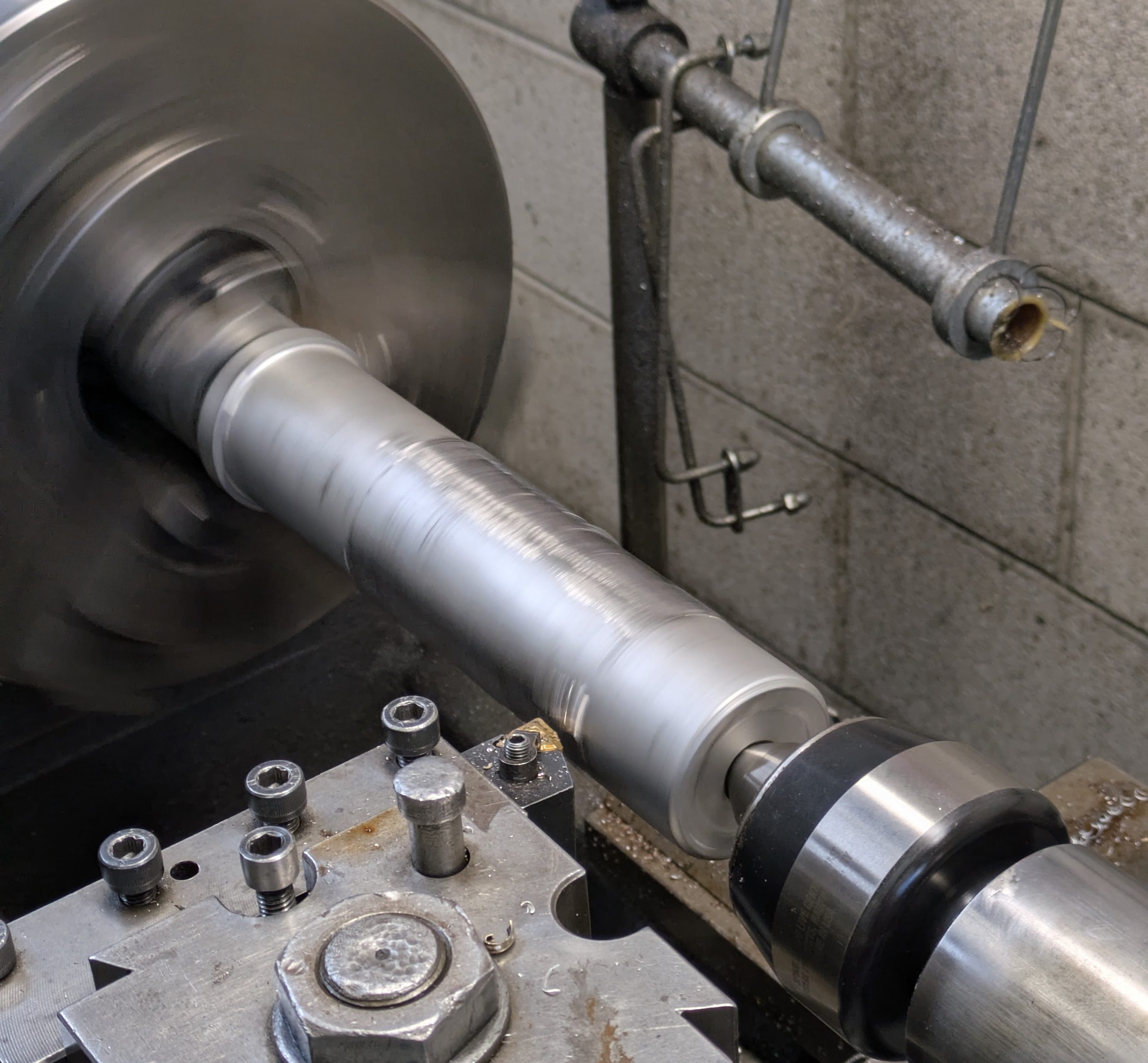
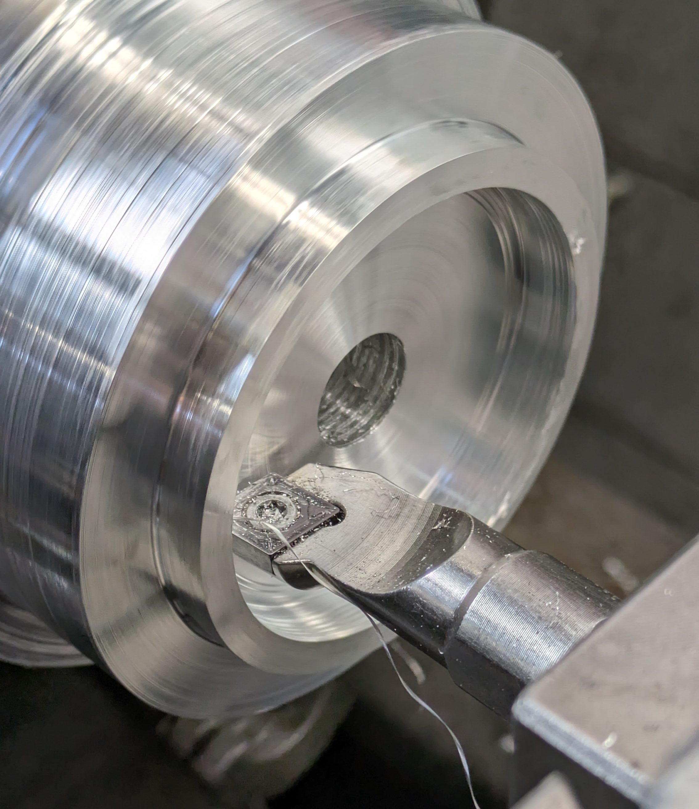
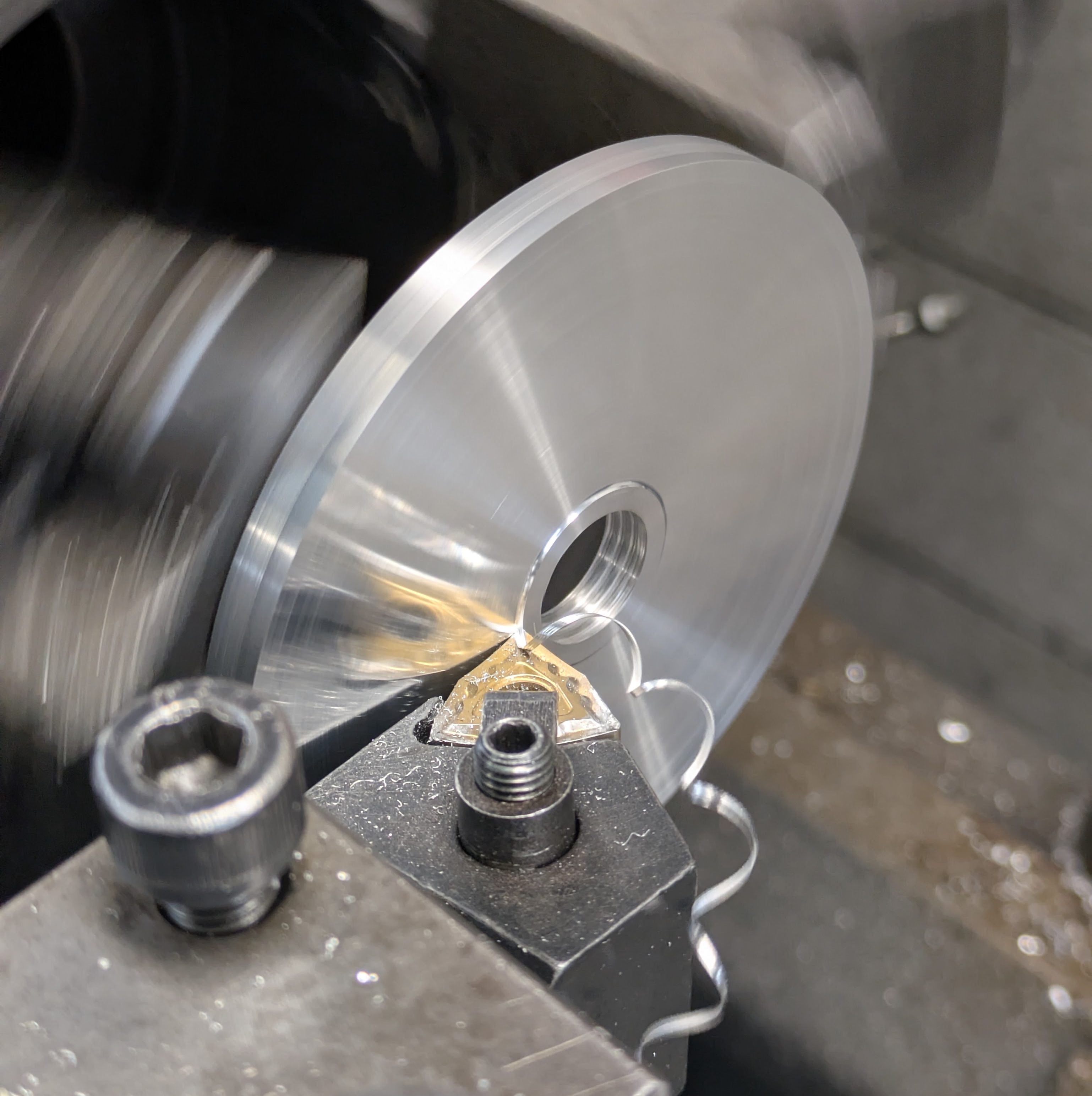
This started as a roughly 6″ long, 4″ diameter slug of 6061 I bought off of eBay (close to the cheapest and definitely the easiest). Fortunately my final OD for the part was just under 4″, so other than the bearing housing, there was minimal material burn. I had generated a drawing to machine to, and most of the dimensions weren’t function critical so I could somewhat vibe-machine, but the bearing ID bore gave us trouble. I scrapped the first part as the OKK (bless it’s heart) is a completely worn out manual lathe and takes frustratingly inconsistent passes when you are trying to hit a 0.0005″ tolerance for a press fit, but luckily I had enough material to comfortably make 3 parts. With the scrap one out of the way (we finished it out to prove all the manufacturing processes), the other two went well.
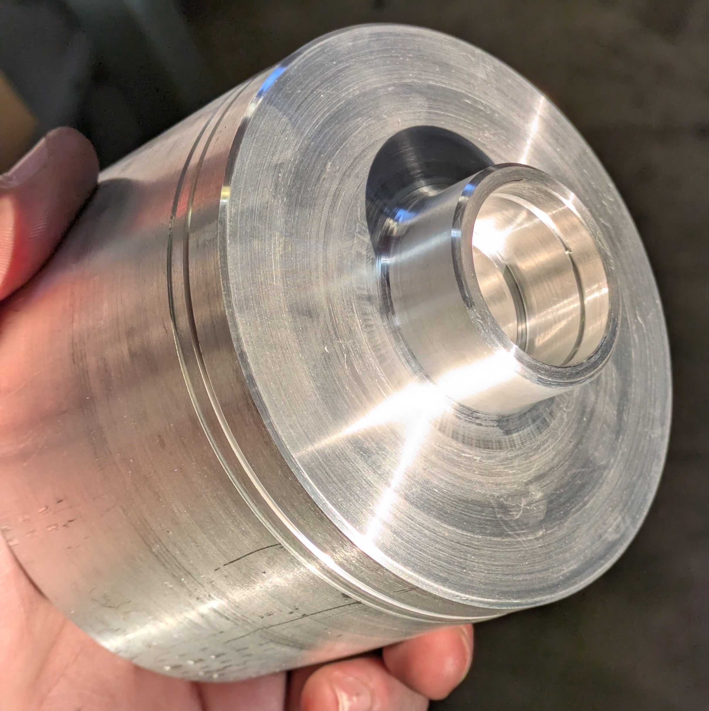
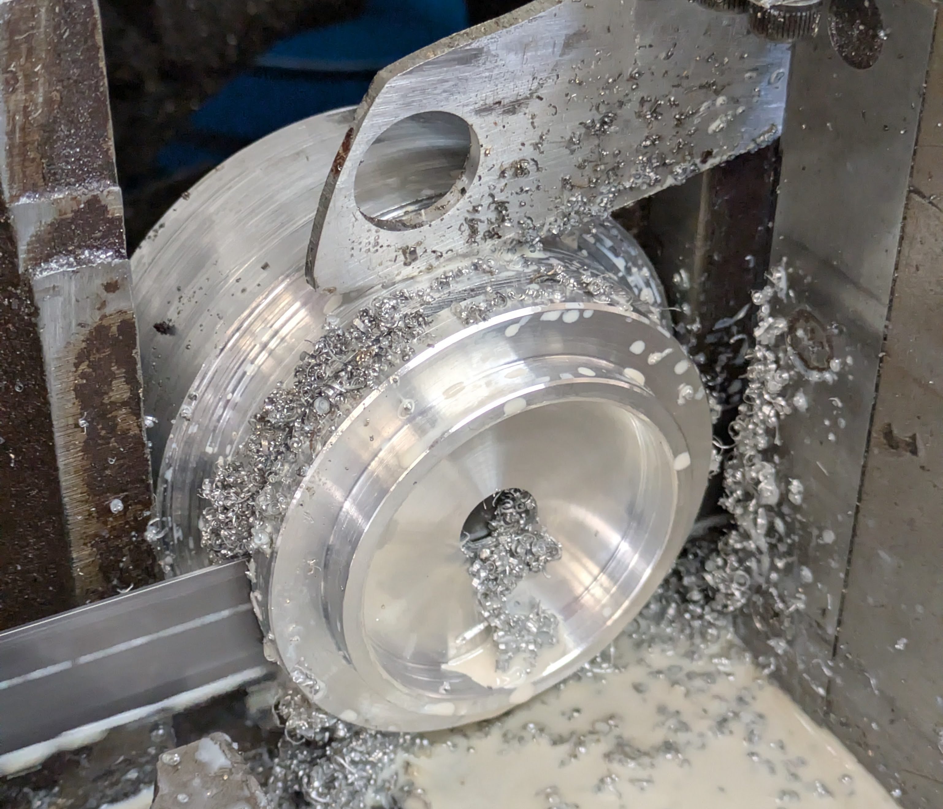
With it separated from the main spud, the back surfaces cleaned up, and all hard edges chamfered on the compound rest, we had two complete tophats. Overall a very successful day and a well-earned evening (and next day) of rest to fight off whatever virus I was dealing with.
We (the “we” being my father) decided custom tophats wasn’t enough trouble. We must anodize them too so they stay looking nice, which is fair after all the time and energy expended designing and building them. We ended up with the homebrew combination of lye, battery acid, and other assorted chemicals, and opted not to go for a dye as it would extend the cycle time and the silver matched the color scheme of the car just fine.
I’ll be totally frank that I was minimally involved in this process. We ended up doing two anodize batches over the course of this whole car project, and other than providing the facilities, tools, and hands when needed, I just did my own thing while Ed the Chemist was busy doing his.
Regardless, they turned out great, and they now look like a finished, professional (albeit hand machined) part.
Moving back to the front, to further verify fitment, I fully assembled the plastic tophat and bolted them into the car. They did, so they were ordered.
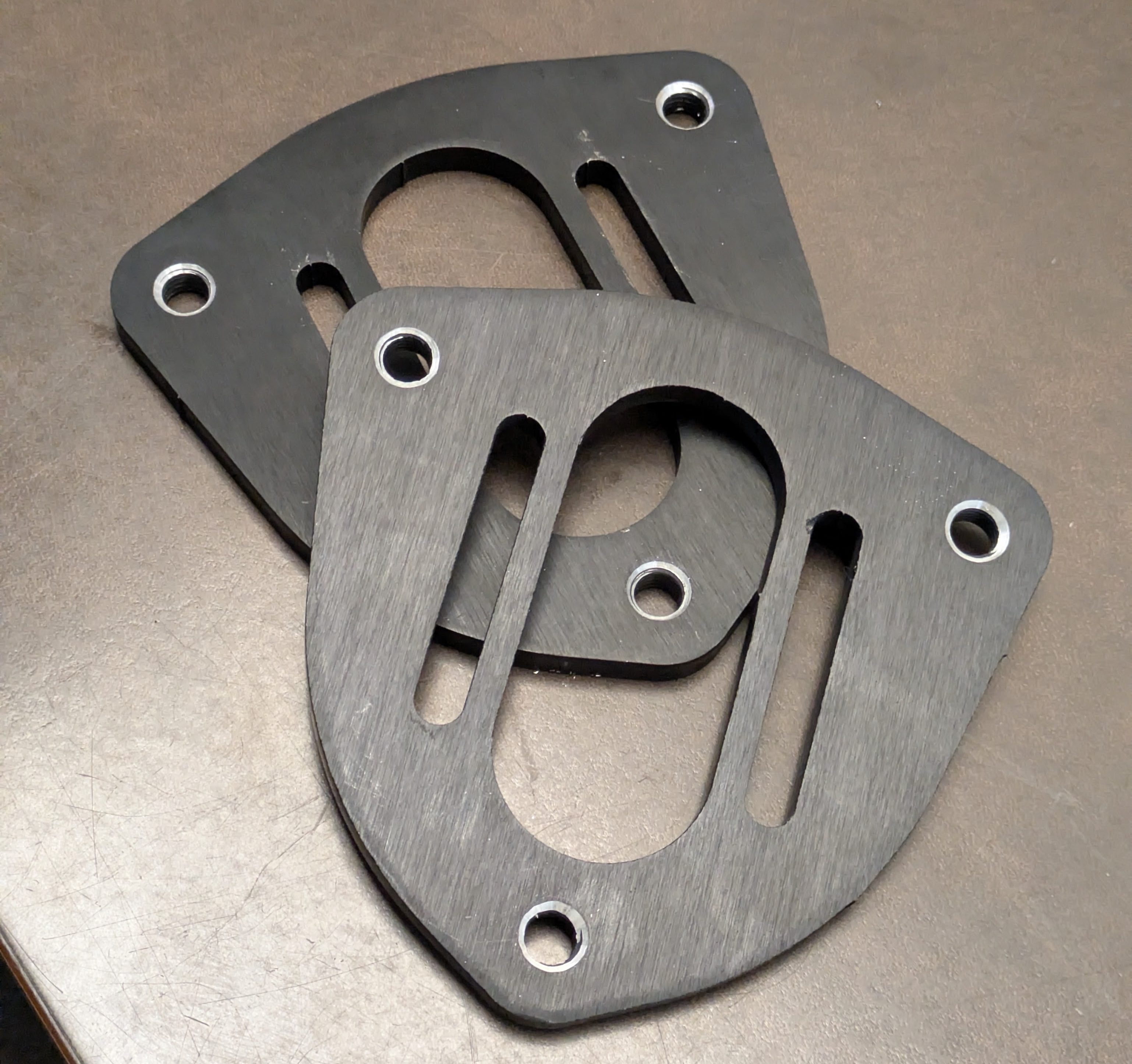
A few weeks later, I was graced with finished parts from SendCutSend. I opted to have these black annodized as the base material is fairly rough as you get it from them, and I wanted to hide some of that ugliness. Other than the material pips from manufacturing needing to be sanded down (where the laser enters and exits the cut shape it’s making), every dimension was within spec.
I took a page out of the Xida/Tractive/949 Racing handbook and opted to do socket head cap screws rather than press-in studs. These are easier to source, infinitely replaceable, and easier to deal with than a press fit. I did chamfer the backside as the bolts had a radius from the thread major diameter into the back of the head, but once assembled, everything fit perfectly.
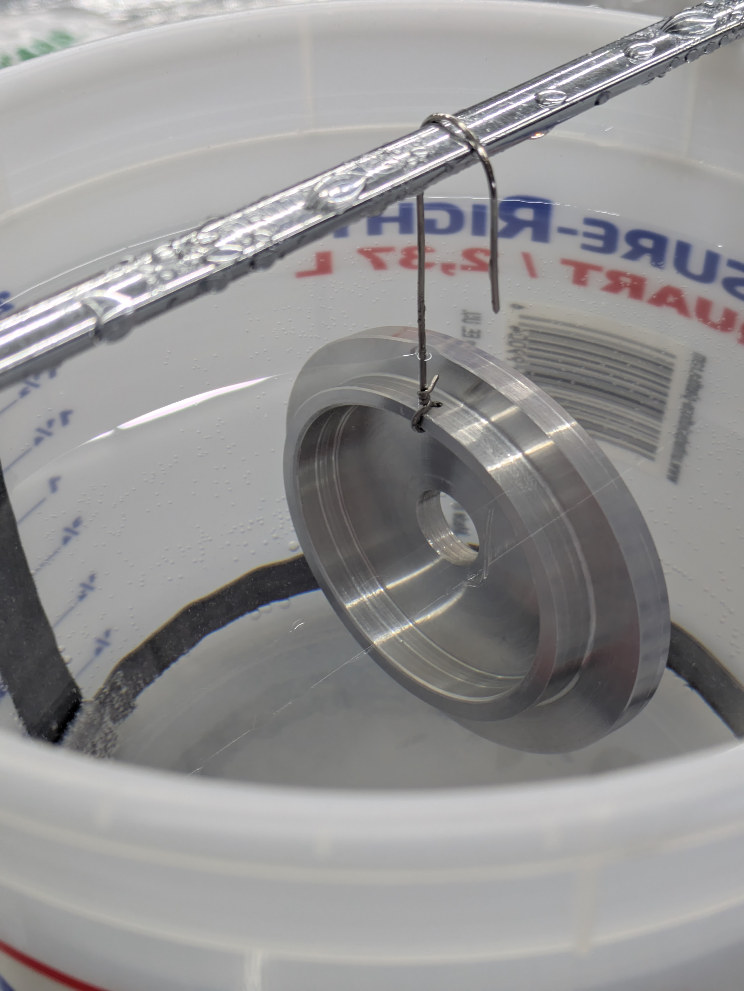
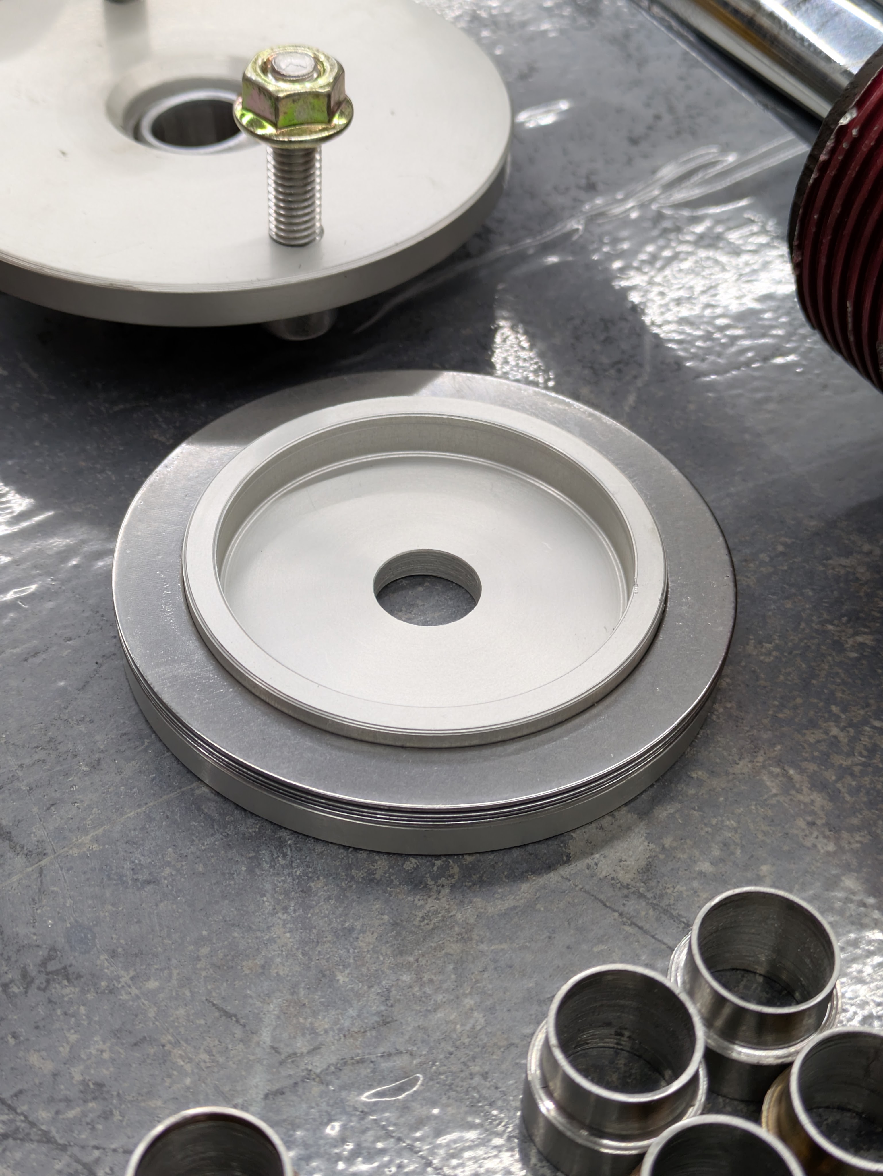
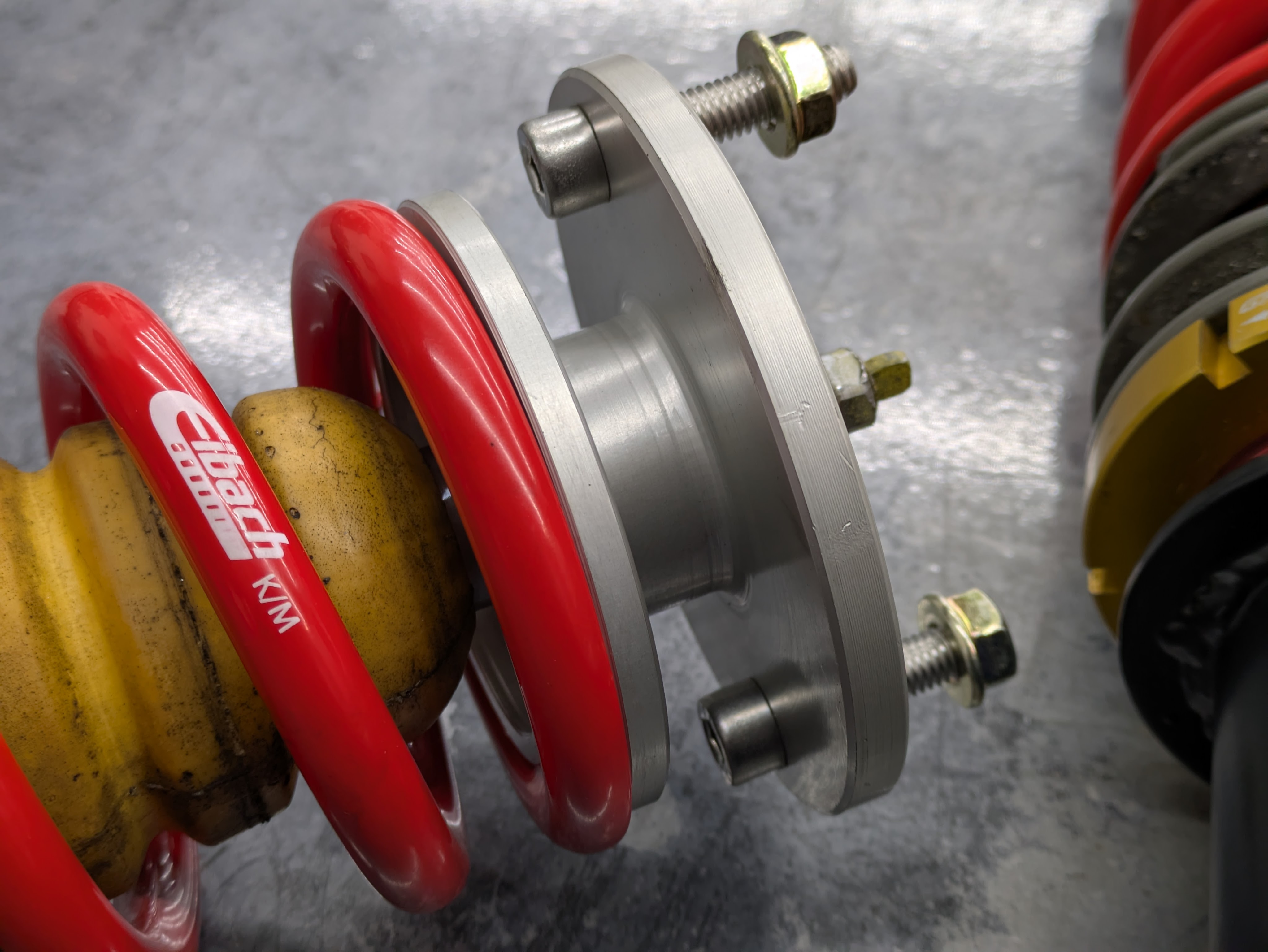
With being the creator of my own tophat program now, I had to turn my own spring perches for 2.5″ springs with the correct stack thickness to play nice with my misalignment spacers.
Misalignment spacers were going to be inevitable as the existing spacers were cobbled together at best, and I was deep in the weeds with custom bearings at this point. I had measured everything out in CAD to know how much thread length I had to play with, and the misalignment spacers were designed and machined around those constraints while still allowing for maximum articulation.
These, like everything else that I can get away with, were machined out of 15-5PH H1025 stainless. Work generates a lot of 3-6″ bar ends of this stuff, so there’s always plenty to go around.
The test fit was a success, so now I just had to make some more.
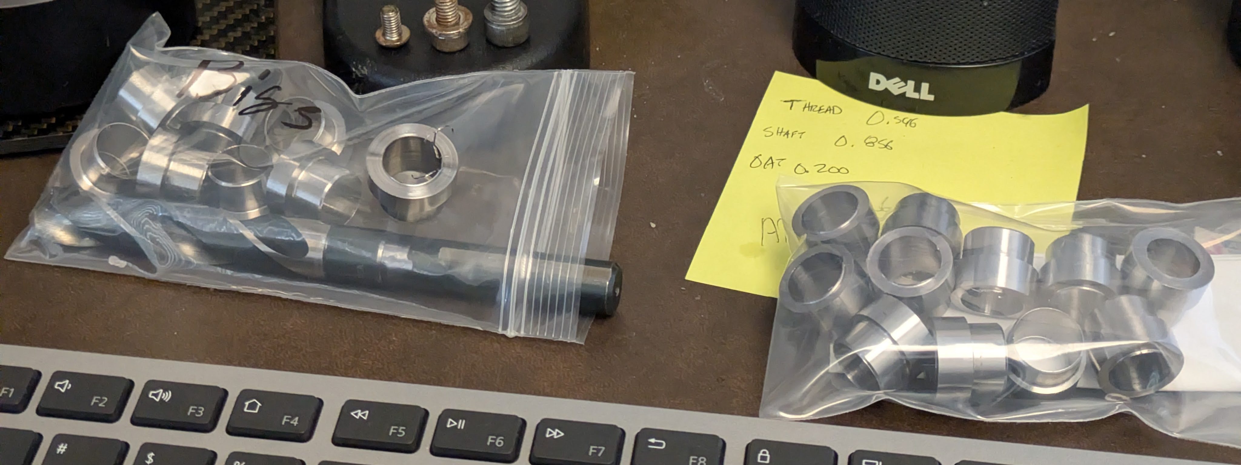
Those of you familiar with high tolerance CNC work know that a warm up sequence is needed to get all the fluids moving and some temp in the machine before it is dimensionally stable enough to start working with. My coworker Ben was watching me make these at a rather slow rate, as I had to set up and tear down every lunch. He offered to make these as the “warm up” program on the dual spindle, bar-fed Okuma lathe and cranked these out way faster than I could have on a manual machine. He finished 20 in 2 15 minute morning sessions including the programming time. There are two different sizes, because as alluded to earlier, there are two complete sets of dampers and there were minor variation between the two.
Since nothing can ever fit right, even the spring adapters for the helper springs needed some love. Different tolerances made these not fit in the Eibach springs all that well, so Lunch ‘n Lathe fixed that up.
With some of the upper components dealt with, it was time to start dealing with the lower housings and mounts. These brought on entirely different challenges and a lot of mental energy was expended determining the best path forward for this admittedly self-induced problem.
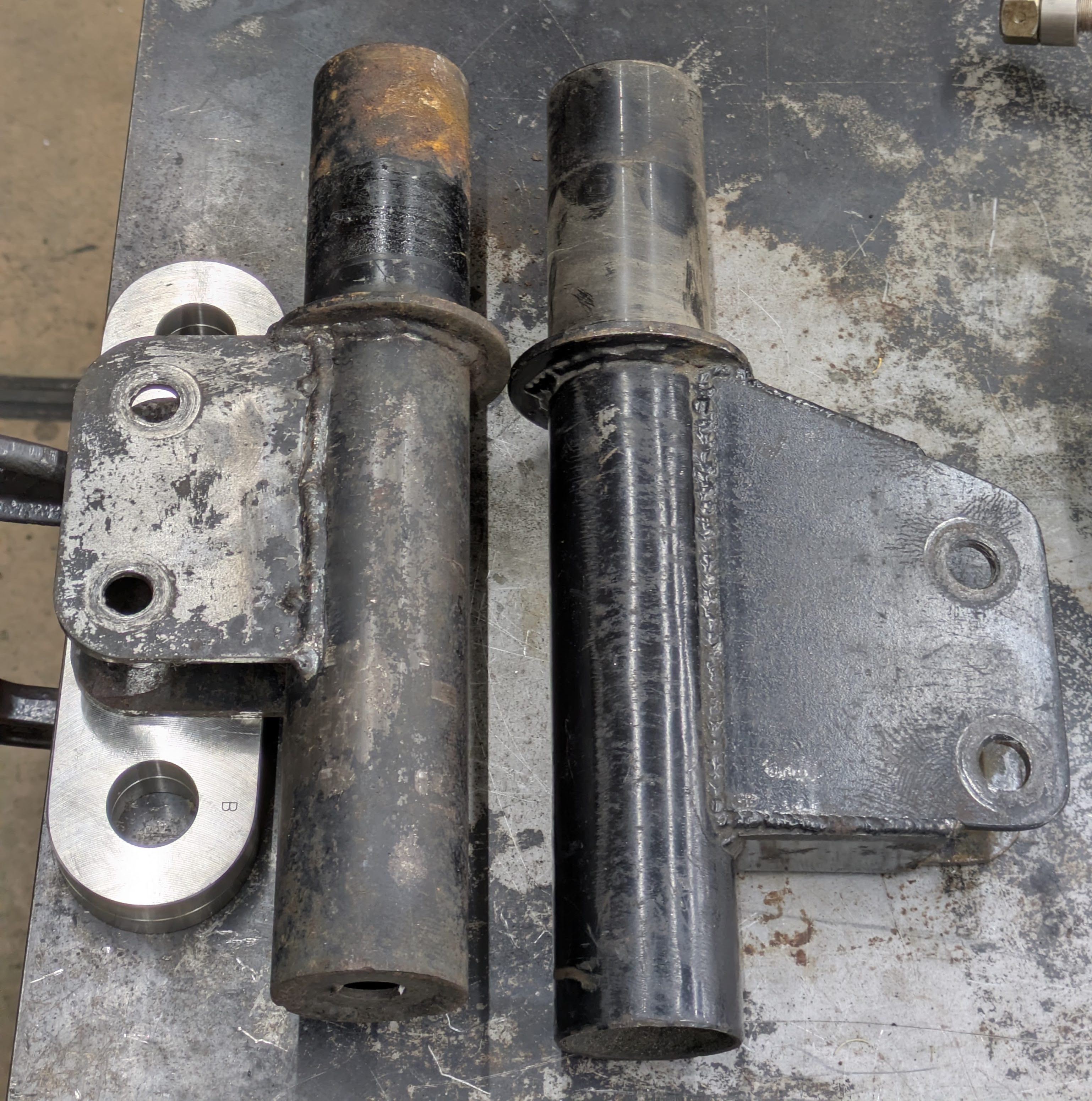
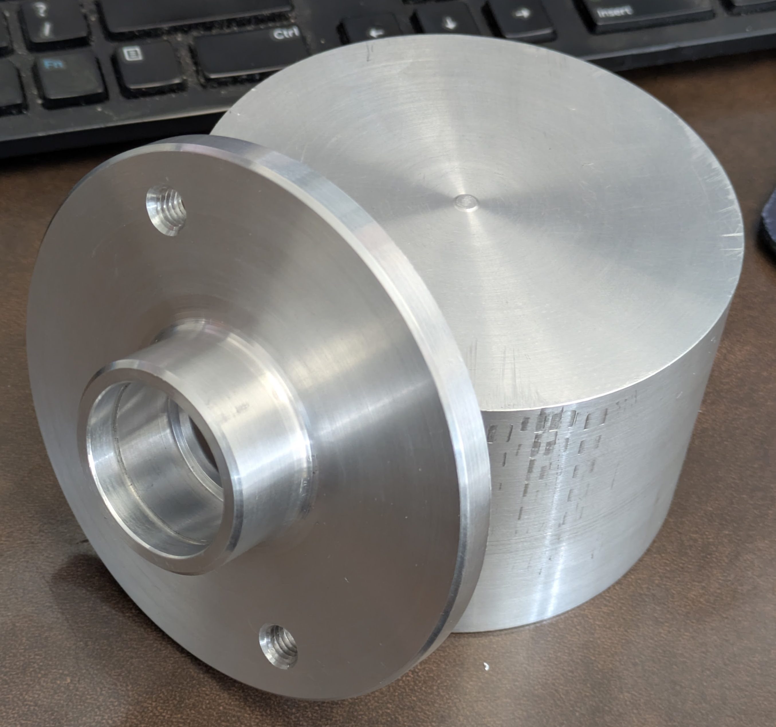
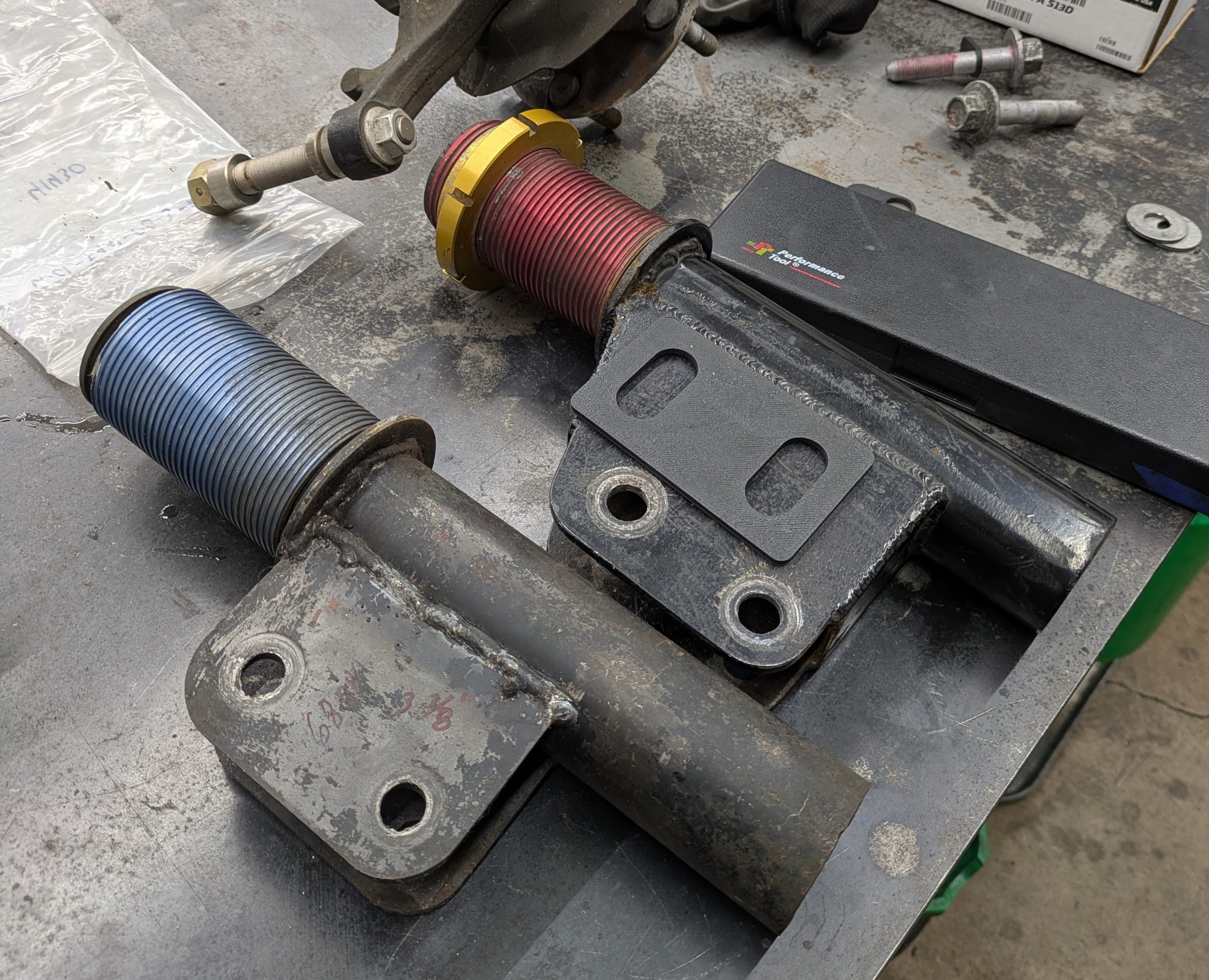
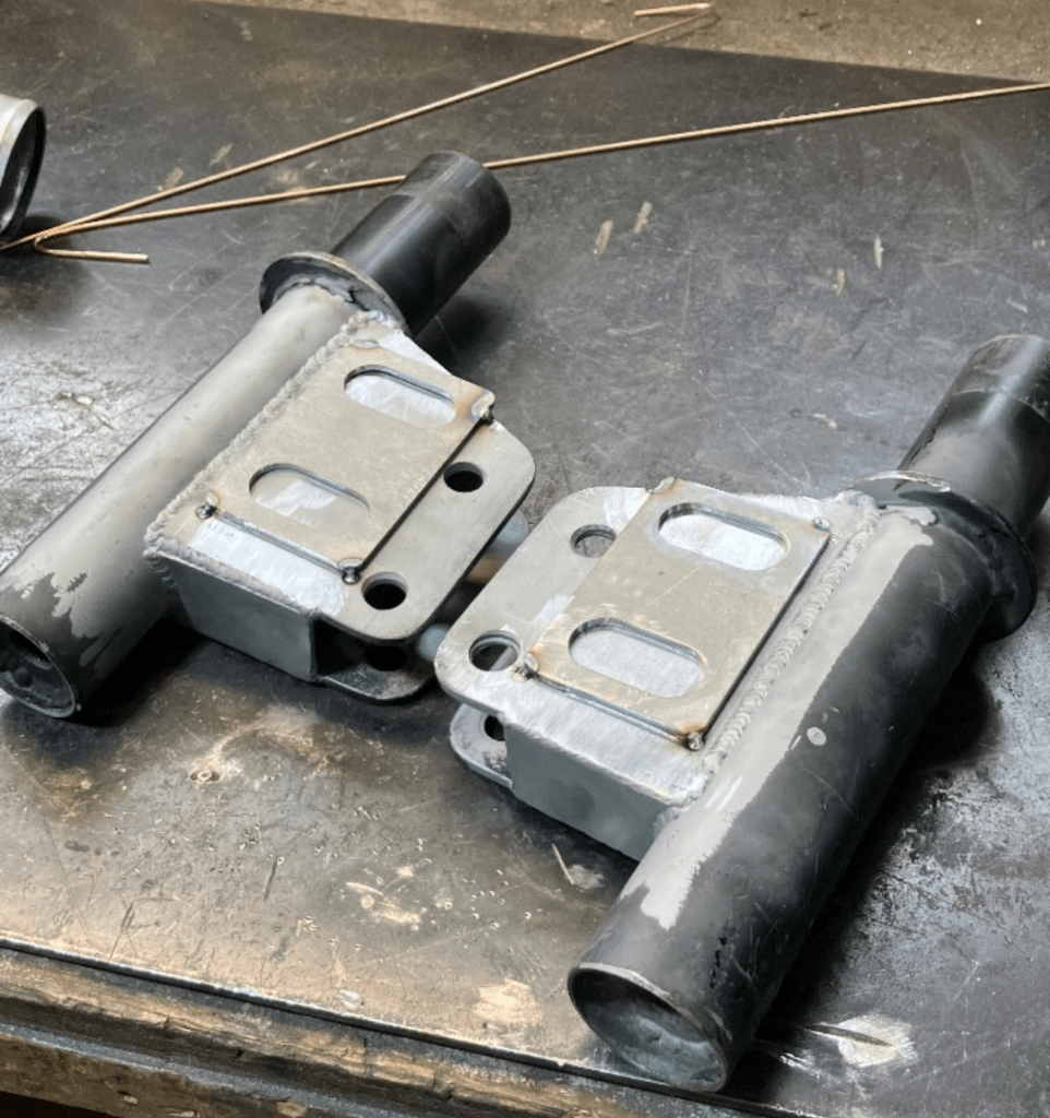
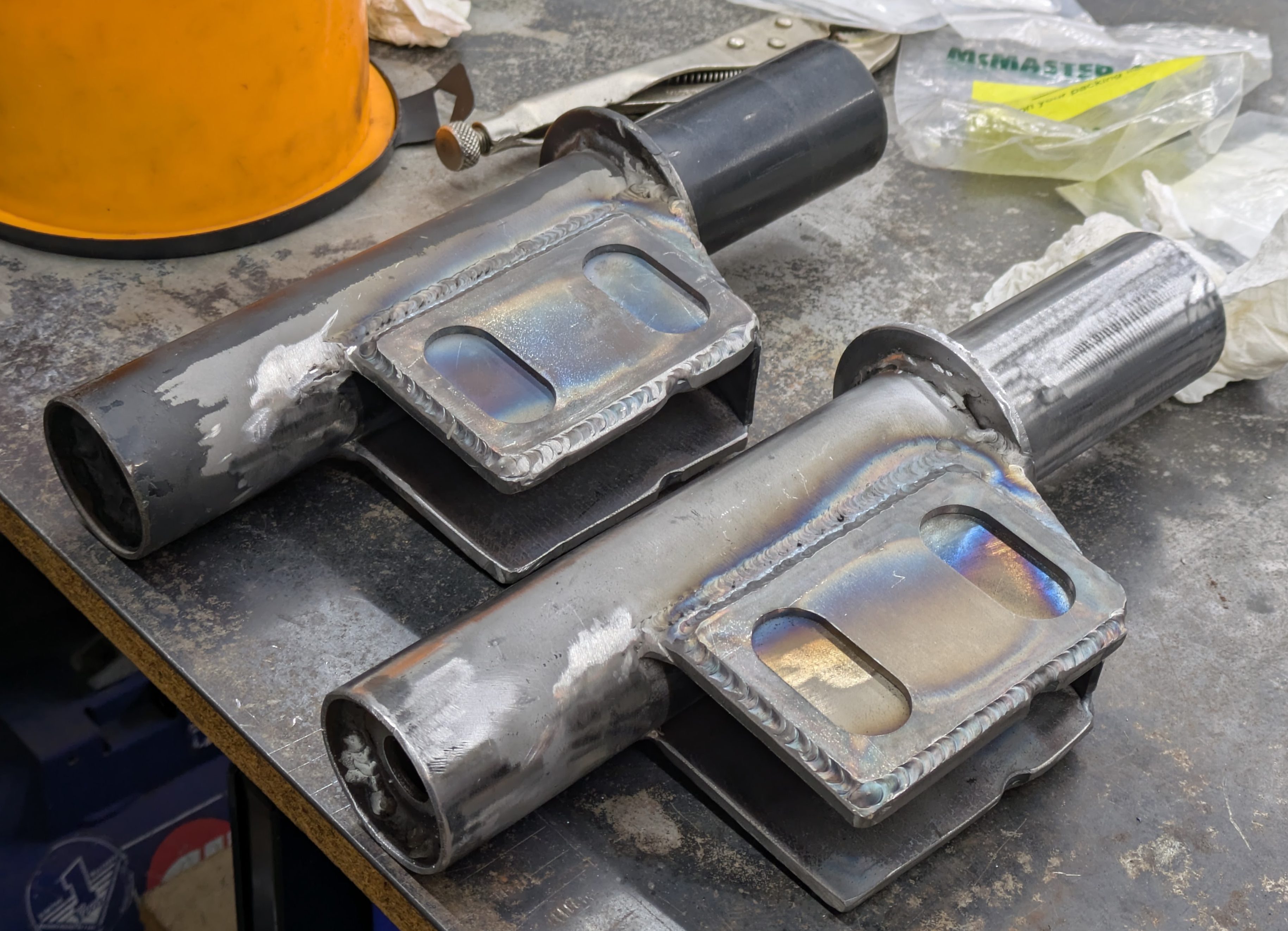
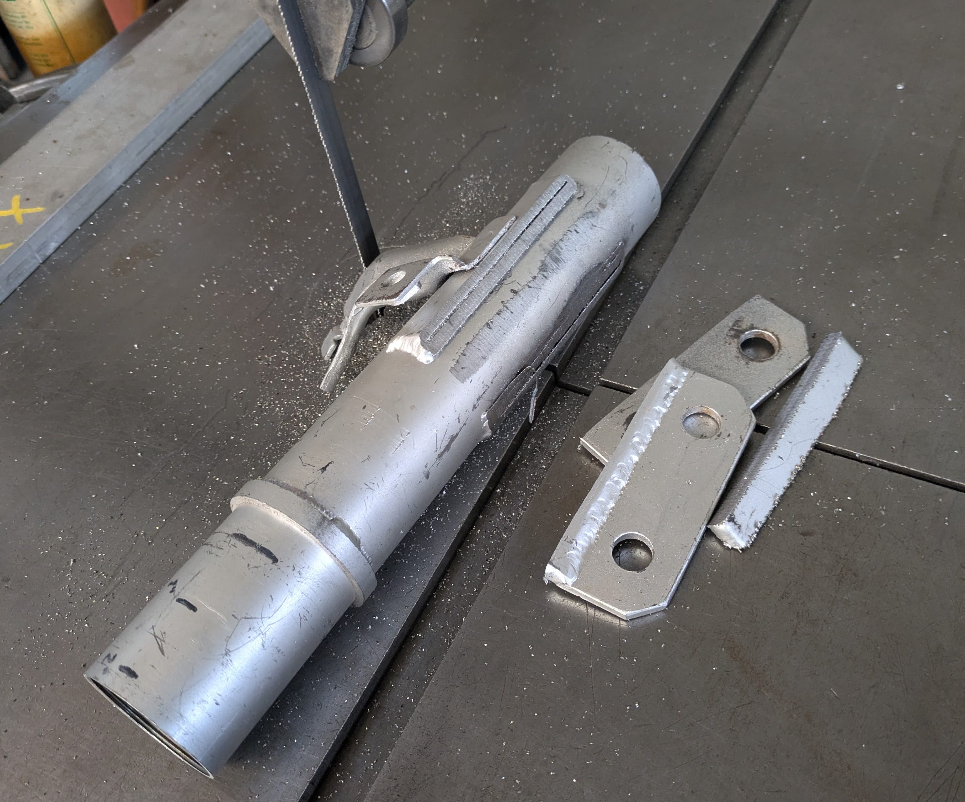
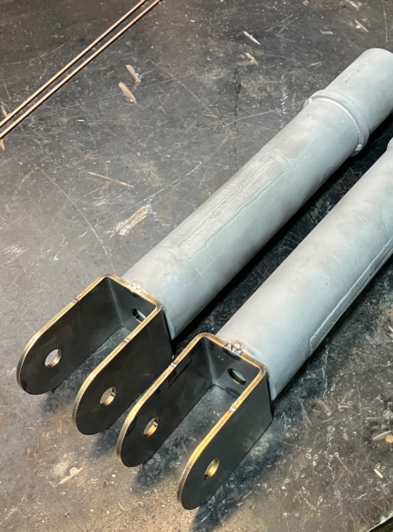
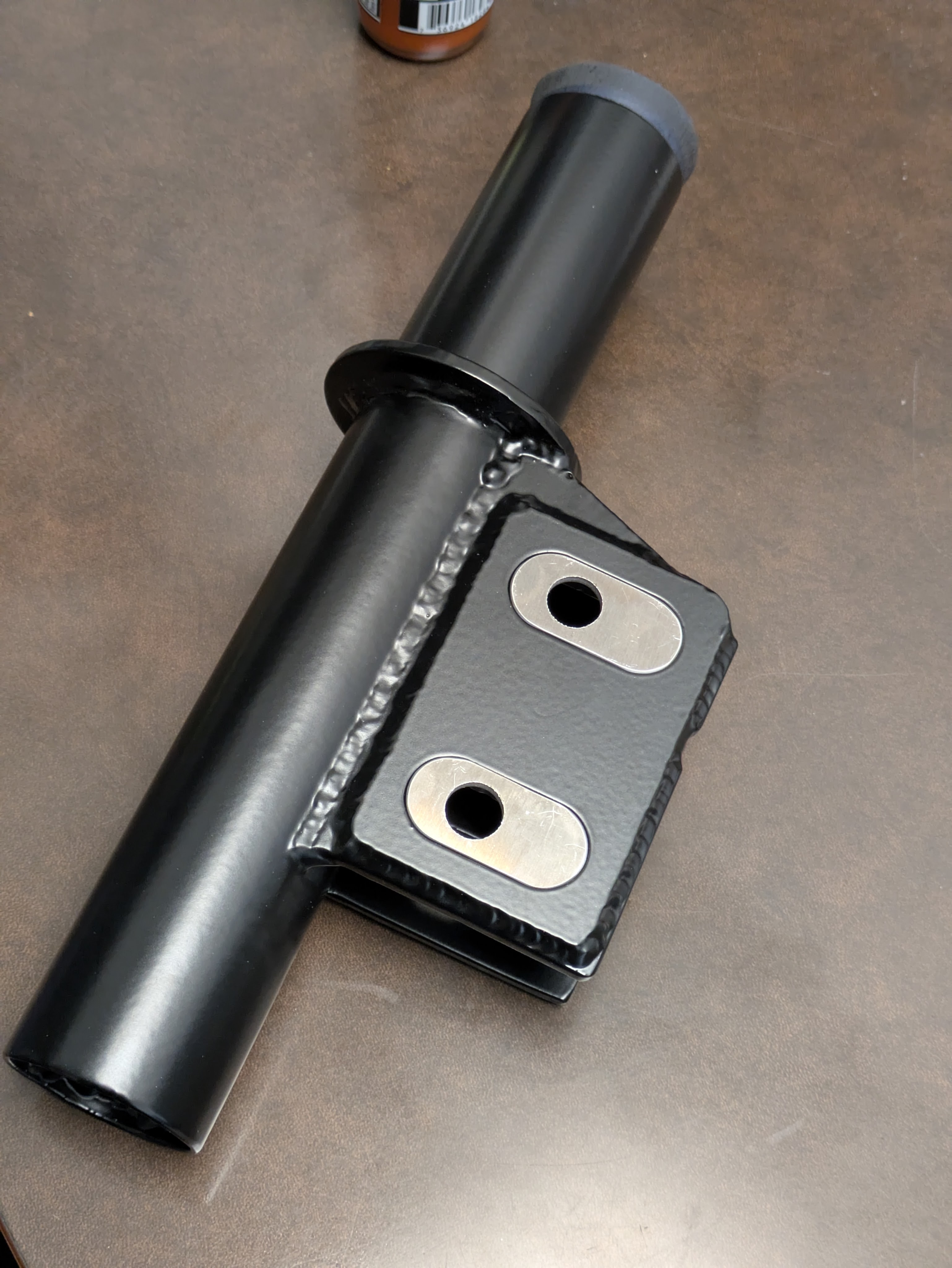
I first needed to show off what we were starting with in the front. This is a good comparison of what Veilside housings(left) were shipped as, and how the Denis pair(right) had been modified to clear an 18X12 front wheel. As I had no ambition to do such a thing, I wanted to bring this heavily modified set back into reason, at least as close as I could get to the dimensions of the Veilside housings. Again, the point of this project now is to preserve the Veilsides so they can be sold, while modifying the already modified parts.
Here is where things get really nutty, and the part that ate up the most time, but also paid back in full at the end.
In a MacPherson suspension, camber can be adjusted in one of three ways:
- Lower Control Arm Length
- Strut angle via upper mounting location (a traditional slotted tophat)
- Slotted bolt adjustment between the knuckle and the lower mounting point of the damper
The first two are established quantities, and also already included in this setup, leaving number three. If you need more camber in a less precise way, you can slot the lower mounting holes to misalign the strut with the knuckle to induce more camber in the spindle without affecting shock angle. If it never slips, this setup works fine. However, if it slips and you start tearing stuff up with your own tire, that’s not so fine, and I really don’t like just trusting friction in an assembly like that. Fine for most, but not for me.
If you want to retain that adjustment option without risk of slipping, there are options. High end aftermarket manufacturers (MCS, and I am sure others) have solved this problem in the form of a camber pill/slug intending to take up the unused space in the slot. As this is the most simple and reliable form of camber control in this location, I wanted to replicate it. I had all the area in the world to work with on the big housings, so I thought “what the hell, lets just do it”.
I started down this path with the idea to use caster shims intended for sprint cars. These are easily available in small increments and a bunch of different shops sell them all intended for their arm setup. I liked this because it was off the shelf, easy, and pretty cheap. The issue I immediately ran into was that all of these, being sprint car parts, were intended for 1/2″ bolts, not the 14mm that the S14 knuckle calls for. This left me with a few options:
- I can switch back to an S13 knuckle, which takes M12 bolts, but that introduces some fitment issues with other components I have.
- I can sleeve down the S14 14mm bores to 1/2 with a thin sleeve, but those are difficult to make with the equipment that I have and I don’t love imperial bolts on a metric car.
- Just make my own. I’m already in this deep.
The last idea won, obviously. The more shocking thing was after I had decided to use a flat camber shim with the same thickness as the retainer plate, I ran it through SendCutSend only to discover that it was actually cheaper than the sprint car shims to get spacers of my own design and fitment that would require minimal post processing, in every increment I wanted.
Jim Belosic, you are a god amongst men for giving us this tool.
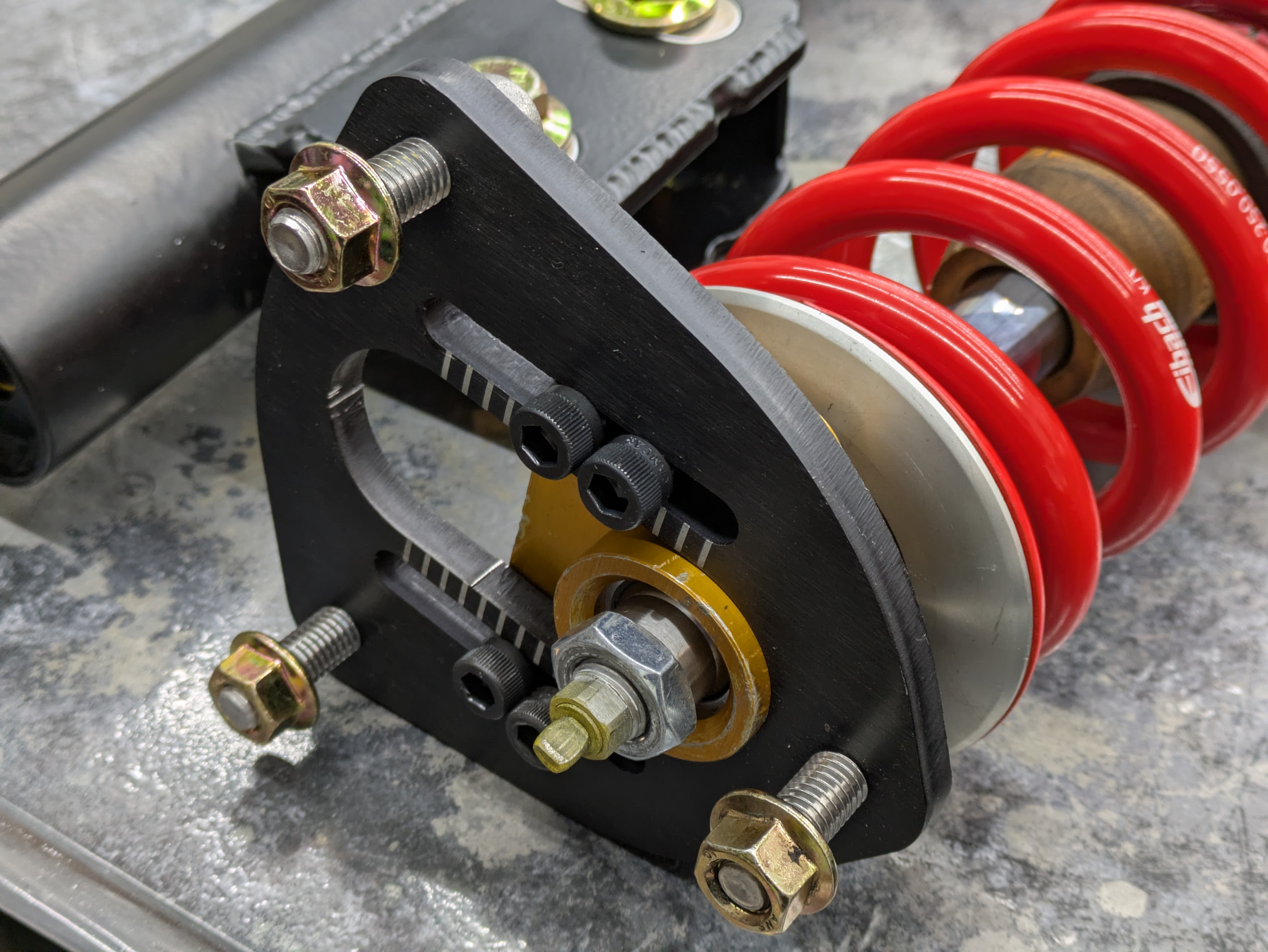
Once I had my pill retaining plates and shims, it was time to figure out where they went on the housing. It was impossible to replicate the distance from the bottom of the spring perch to the bolt holes between the modified housings and the Veilside ones, just on the nature of the top reinforcement being slanted. This meant I had to essentially guess on this location, which on a 1 piece shock car, place a critical importance in bump/droop travel as it sets your operating envelope of the shock. Not being able to bolt these into the car to check before I committed was definitely not ideal, but I knew the modded housings were too tall. I settled on about 15mm lower on the body (so taller in terms of the height of the car) than the Veilside housings, which worked out very well in the end.
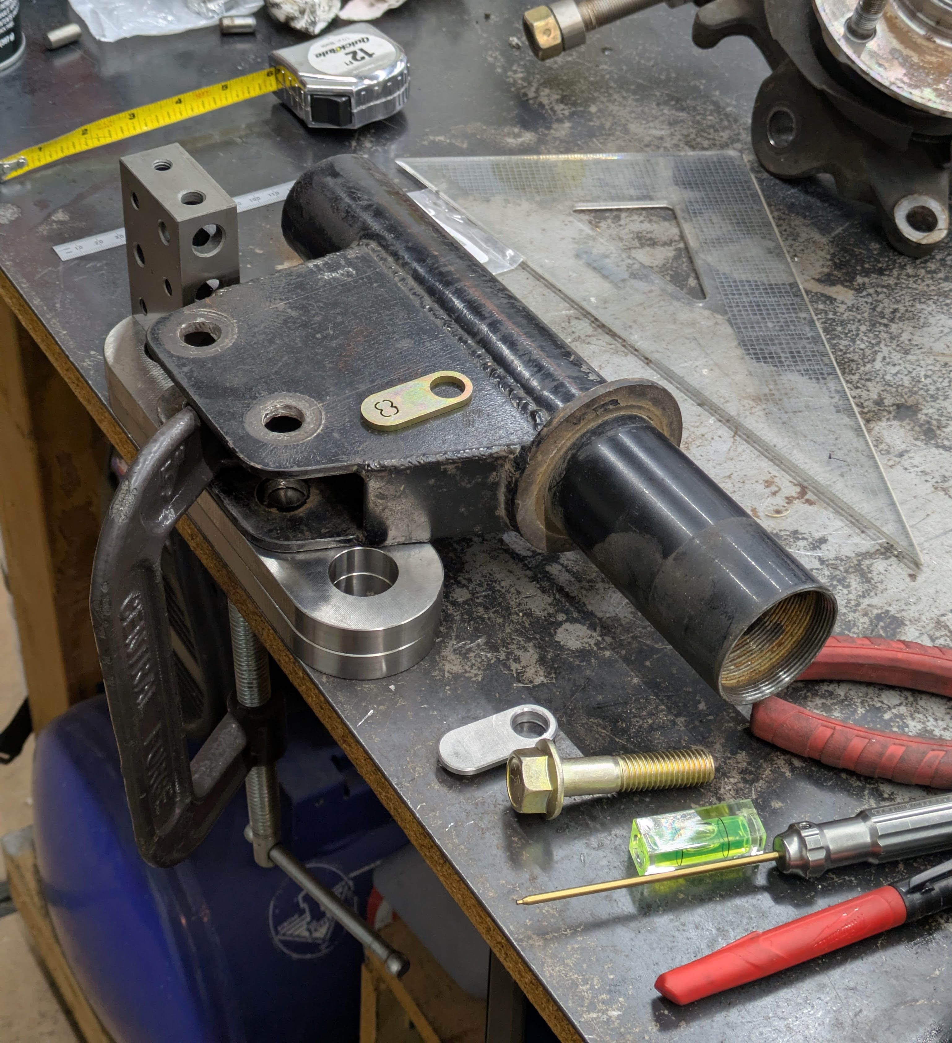
Ok, now that I’ve chosen a vertical location in space, I then needed to pick a horizontal location, and figure out how to assure they’d be inline post-welding/machining. This presented some significant challenges as the modified housings were very handmade, and I didnt trust that the centerline of the mounting ears was actually in line with the centerline of the tube. Also, if one of the ears was welded at a different intersection point than it’s partner (neither were tangent), that would also make pulling a reference very difficult as they could be in two completely different places.
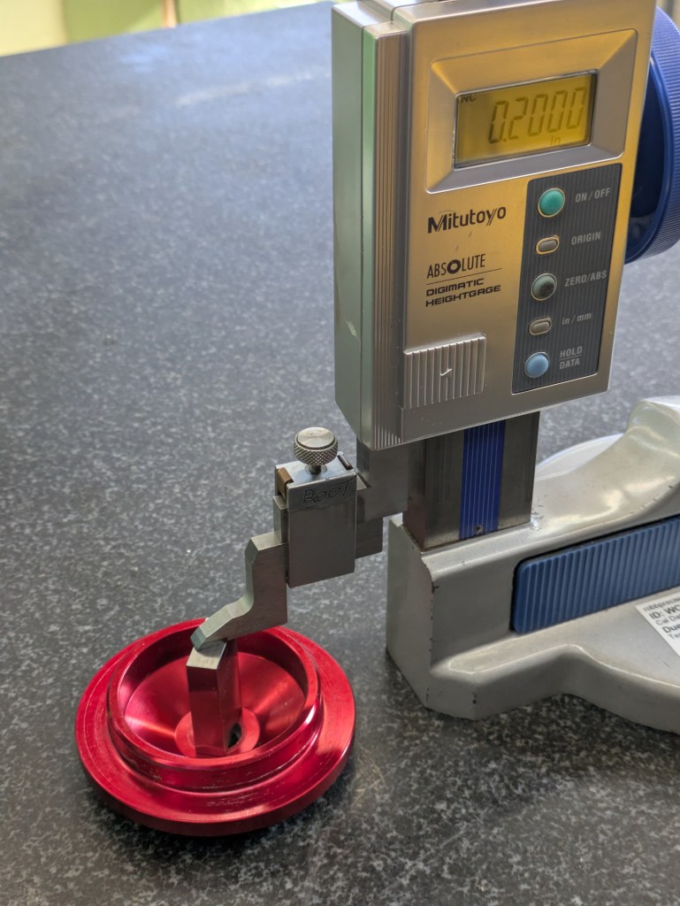
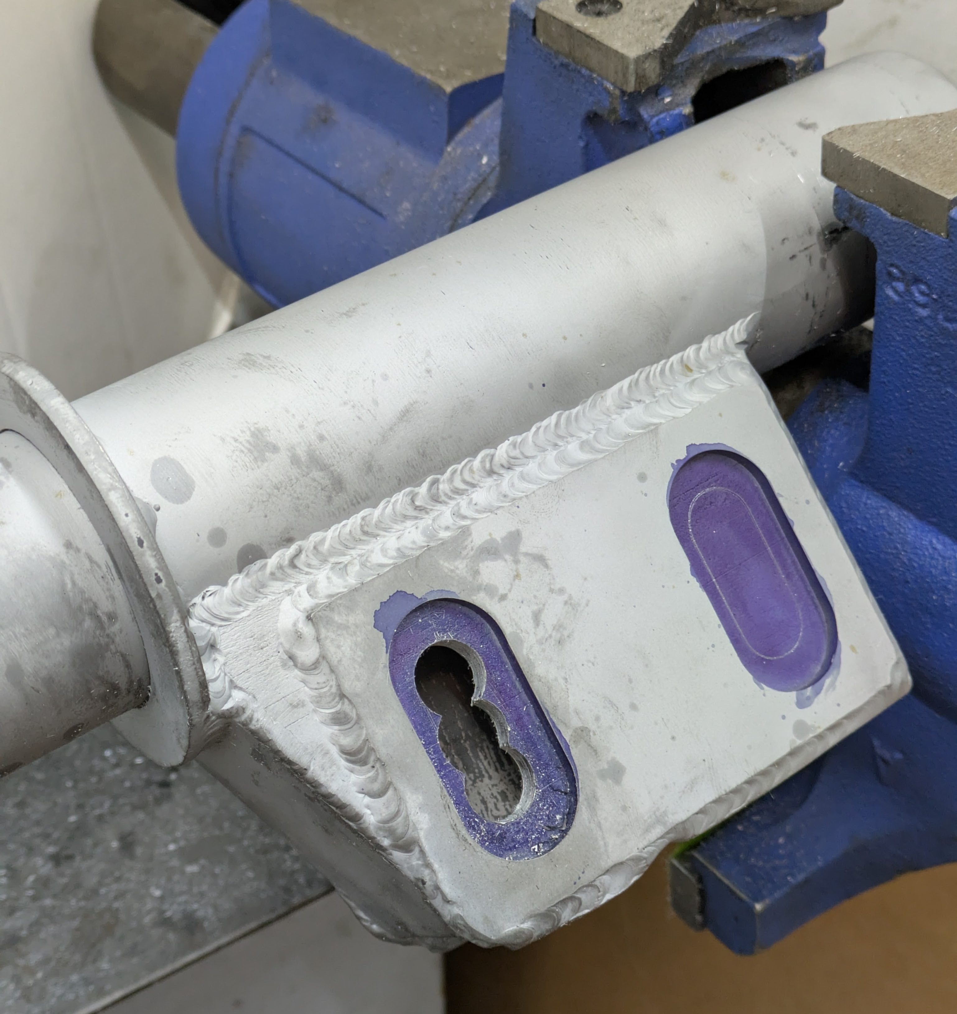
I hatched a plan to use verifiable datums in the form of the tube itself (as they are the same diameter) and the base where the spring perch rested as they were effectively identical side to side. With a large amount of borrowed metrology equipment from work, I was able to use a combination of V blocks and height gauges to fixture everything.
Heres the detail of how I set it up:
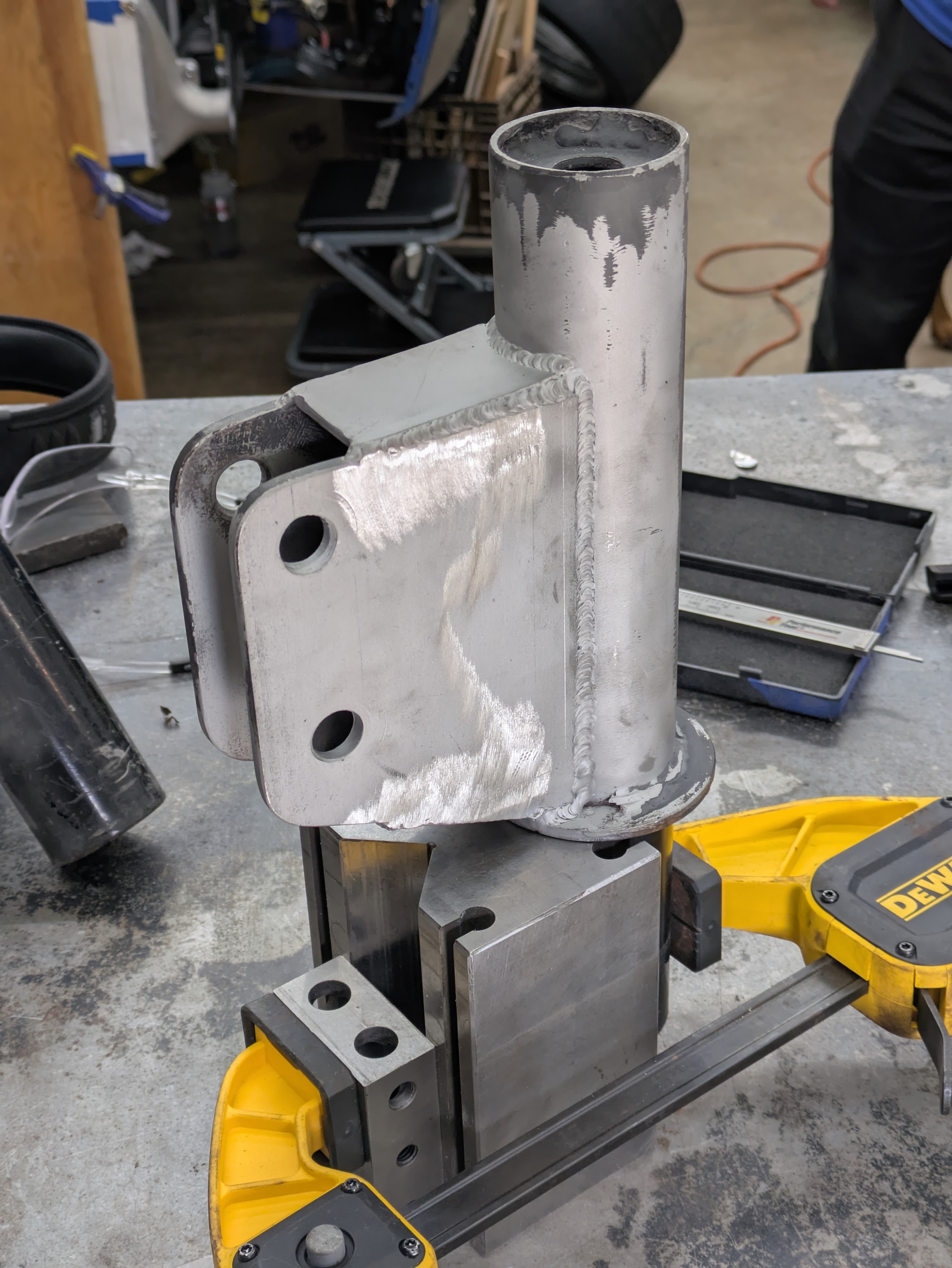
To estabish the vertical positioning of the plates (how far up/down the mounting ears they were), I used a 6″ V-block on its side to orient the housing vertically, with the spring perch flange resting on the top of the block. A simple carpenter squeeze clamp held it in place to ensure that it was firmly seated and square. From there, I was able to scribe a line at the height I had determined earlier with the carbide tip on the height gauge. That one was pretty simple.
Establishing horizontal position (how far away from tube centerline the plates were) was more difficult, as I wanted to push them into be fairly close to the Veilside positioning, but I couldn’t due to interference from the existing weld from the mounting ears to the tube. I also knew that the Veilsides were the minimum acceptable offset before wheel and knuckle fitment become a serious problem. This was also a kind of “wing it” measurement where I had the same location as the Veilside had, plus or minus some to adjust distance from the strut to the knuckle to dial in wheel fitment.
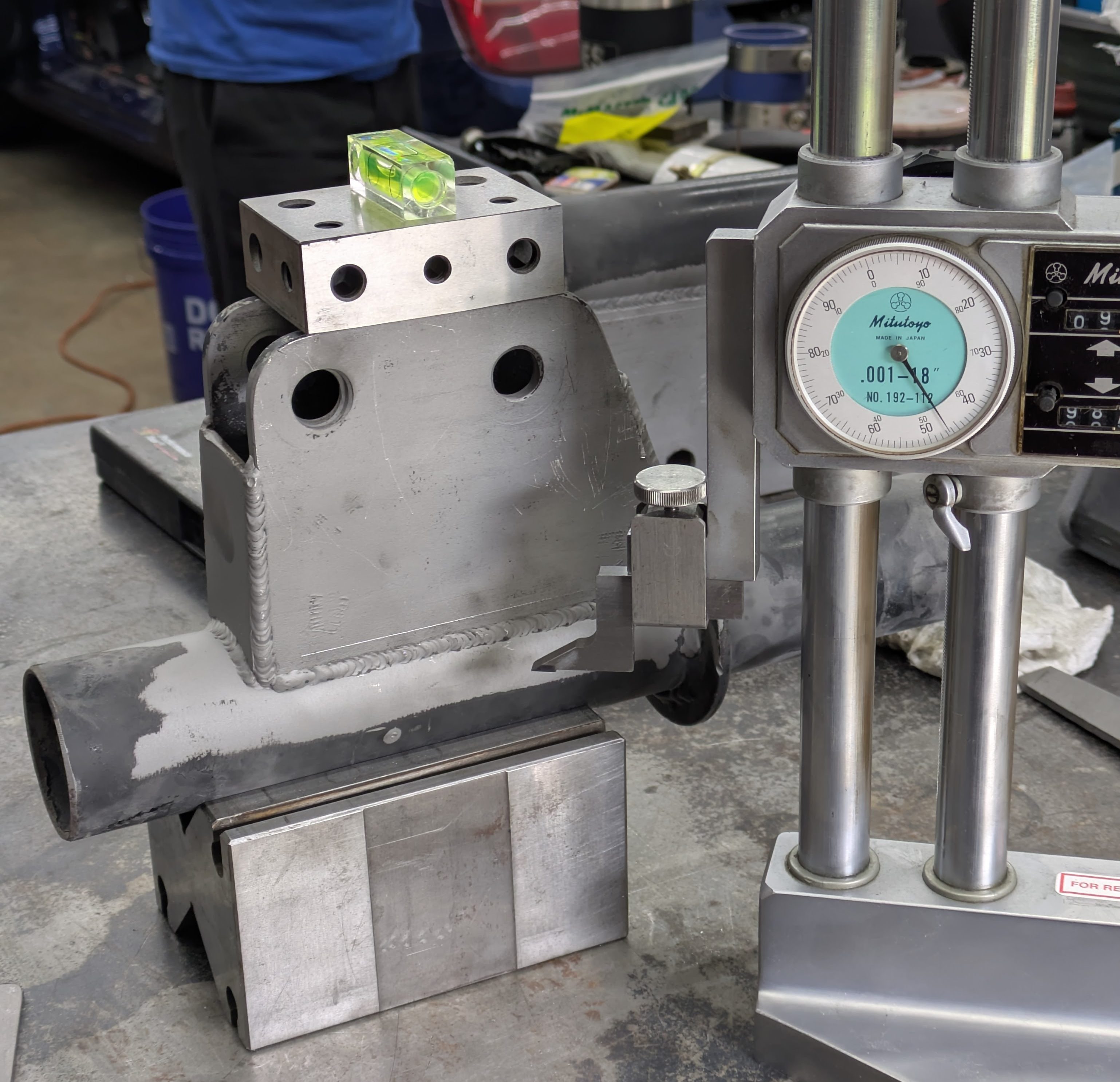
This seutp involved the same V-block, this time oriented on its side with the ears of the housing vertical. I put a 1-2-3 block across the ears and used a level to get it close, then verified with the height gauge itself to make sure the ears were parallel to the bench. I then performed a similar scribing operation to the vertical line. For both the operations, that once the height was set, I could lock the height gauge in place and scribe it, knowing the setup would be identical due to the repeatable fixturing strategy.
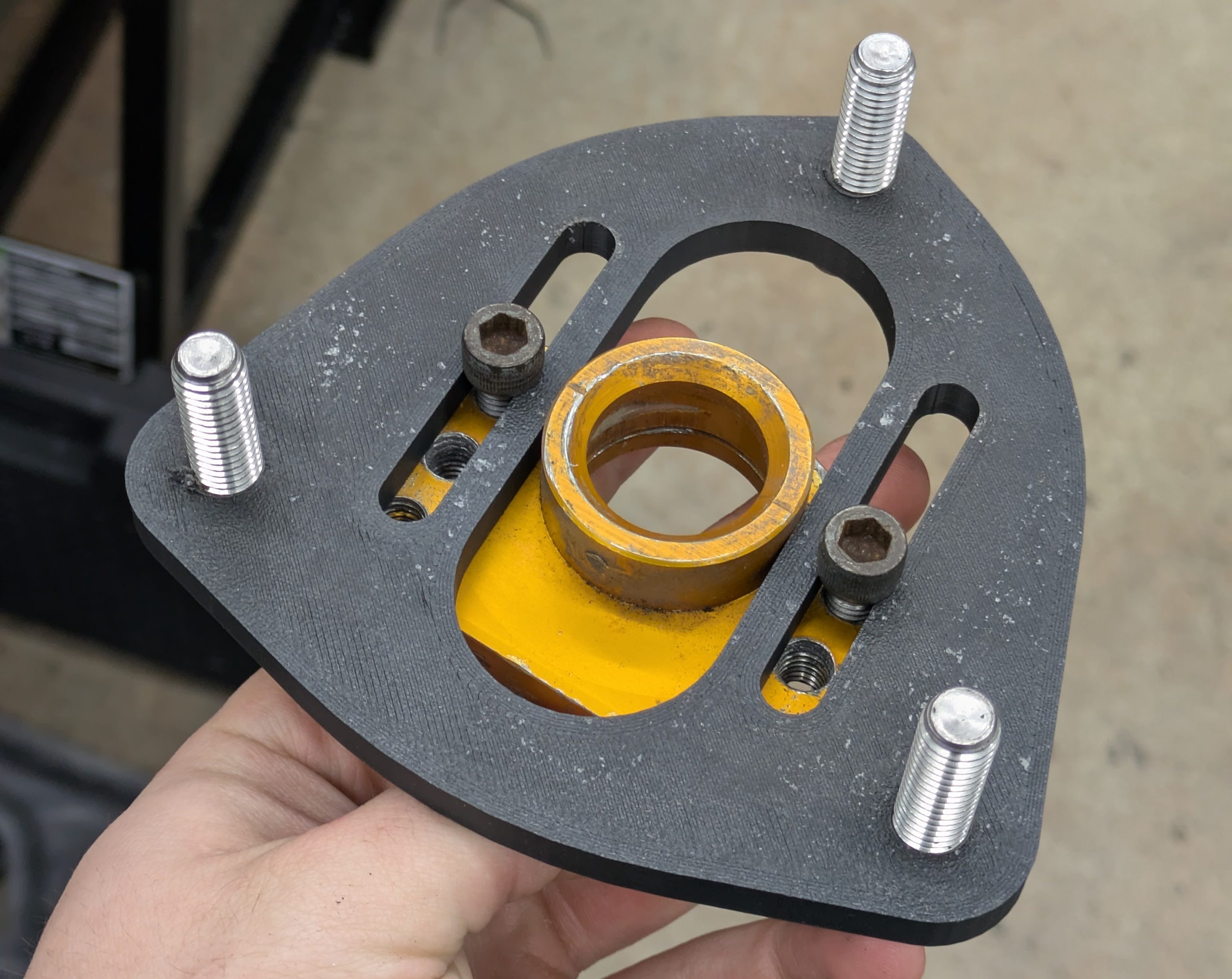
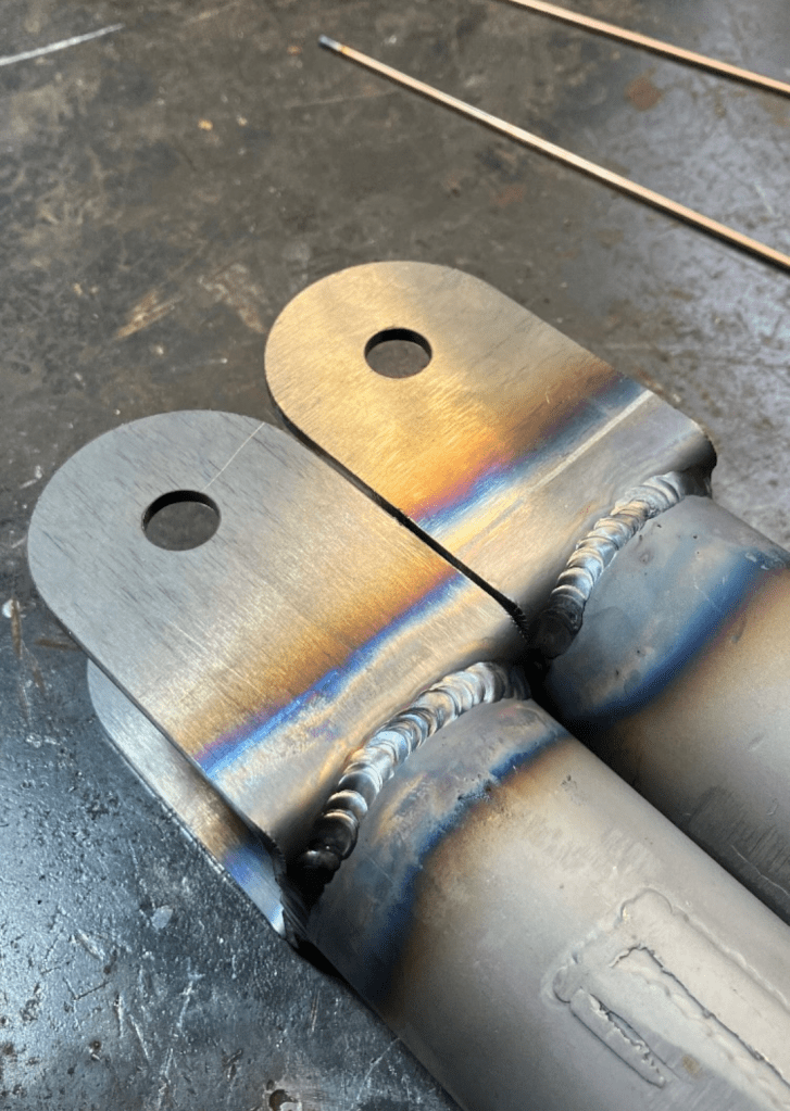
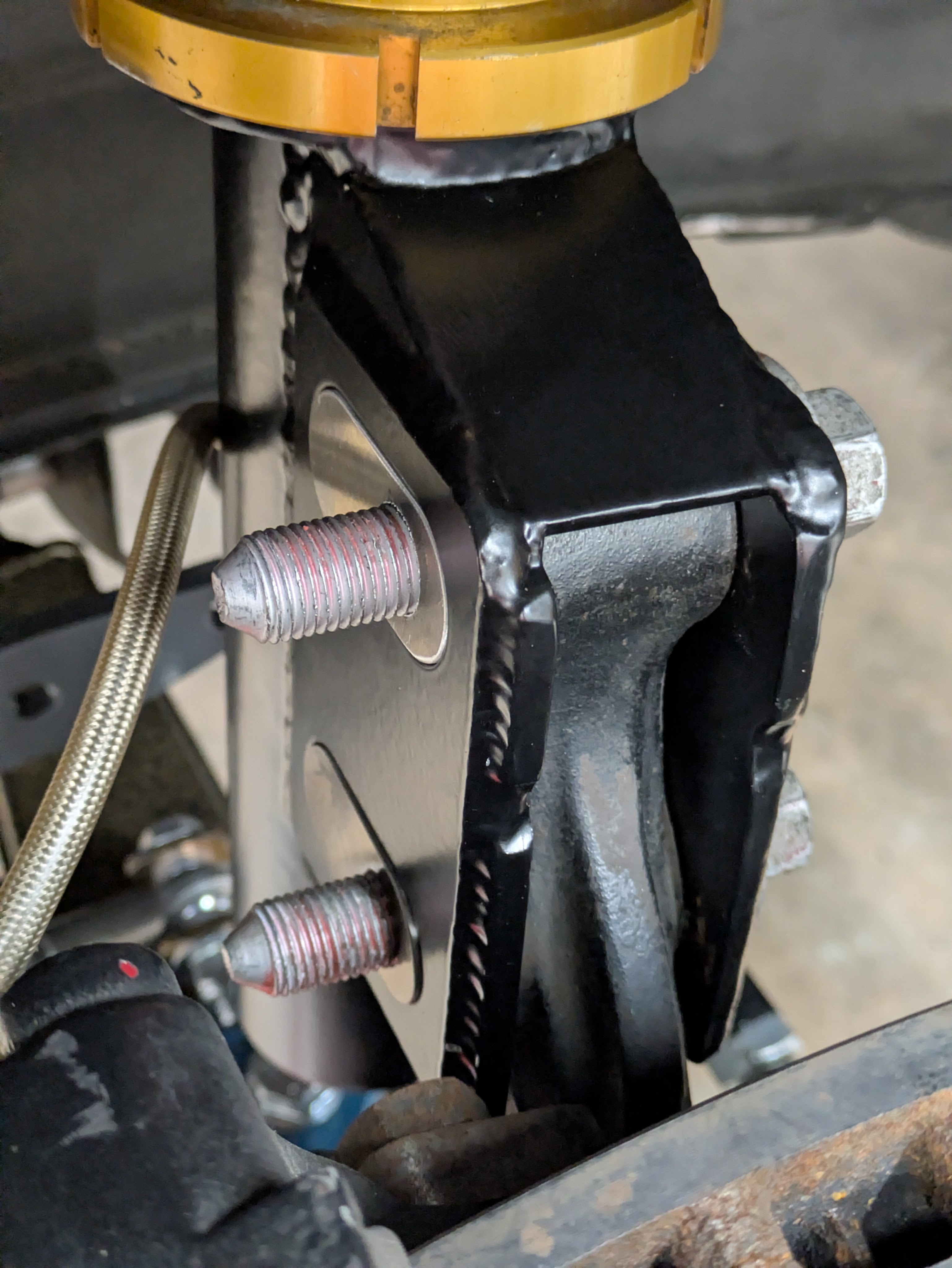
Once the locations were scribed, it was time to get them welded. If you look in one of the first image of this set, you can actually see that I made an attempt to fixture the two ears with a tie tab between the two plates. This ended up not working as the distance was slightly too small(the housings taper slightly), so I just had to cut it off.
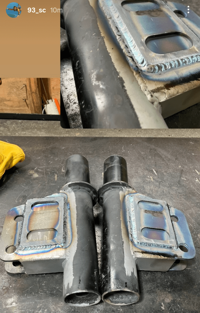
The homie Ethan, who had done all the welding on my car up until this point, followed the locating lines perfectly and I left his place with hope that this project might turn out ok after all.
Once I had the housings back from welding, I chopped off the remaining material around the ears and sandblasted them in prep for powdercoating. It also gave me a chance to finish out any sharp edges and small defects.
The only thing holding up finishing work was putting the slots for the bolts to pass through. I was foolish in thinking that I would be able to slot these with a start drill and Dremel with an endmill, and promptly gave up and brought them into work the next day.
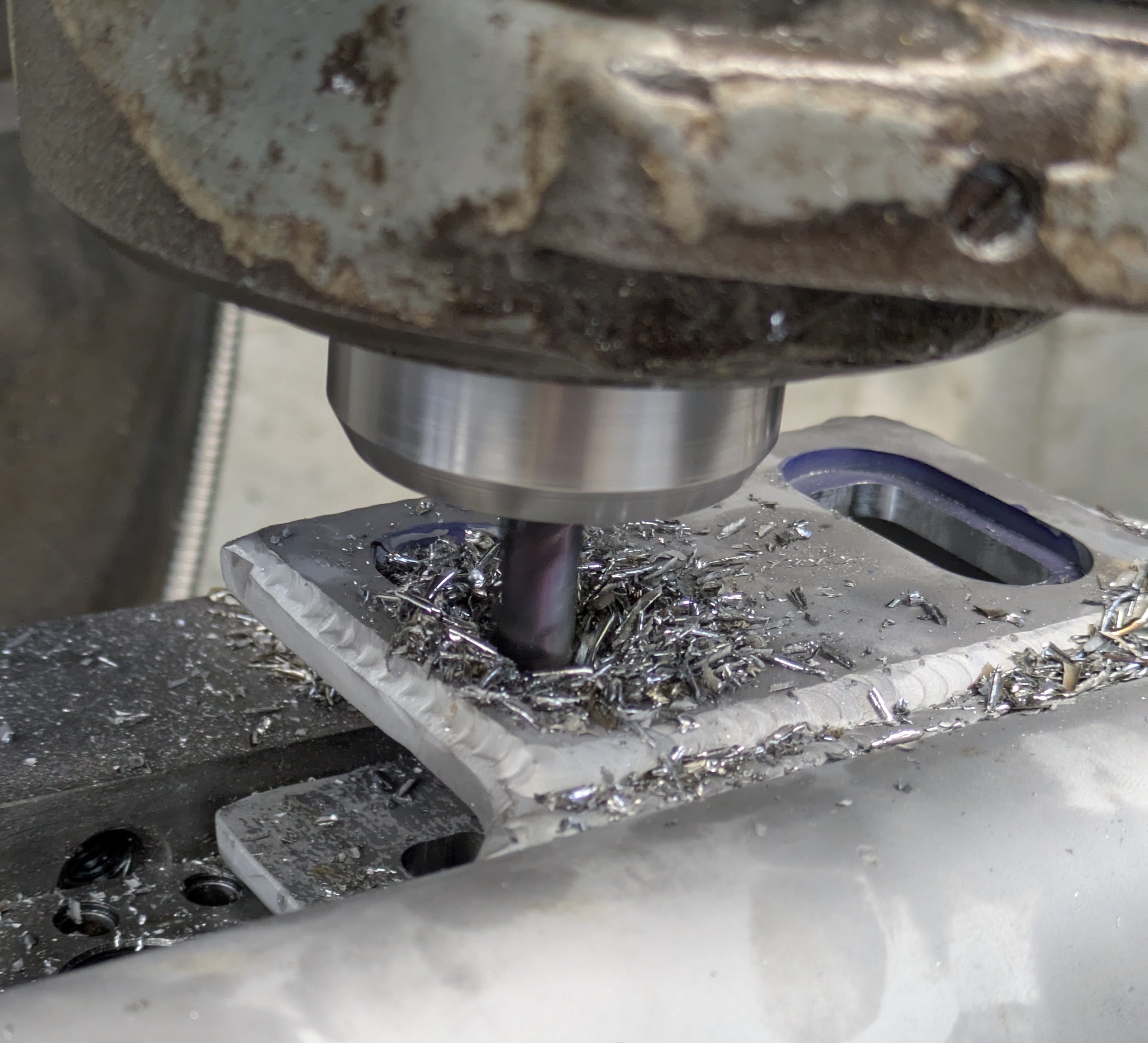
I stayed late that evening to fixture them in the manual mill and do them properly with an endmill. They turned out way better in a fraction of the time. Thanks Ben for staying late with me to talk shop and make slots. From there I was able to drop them off for powdercoat.
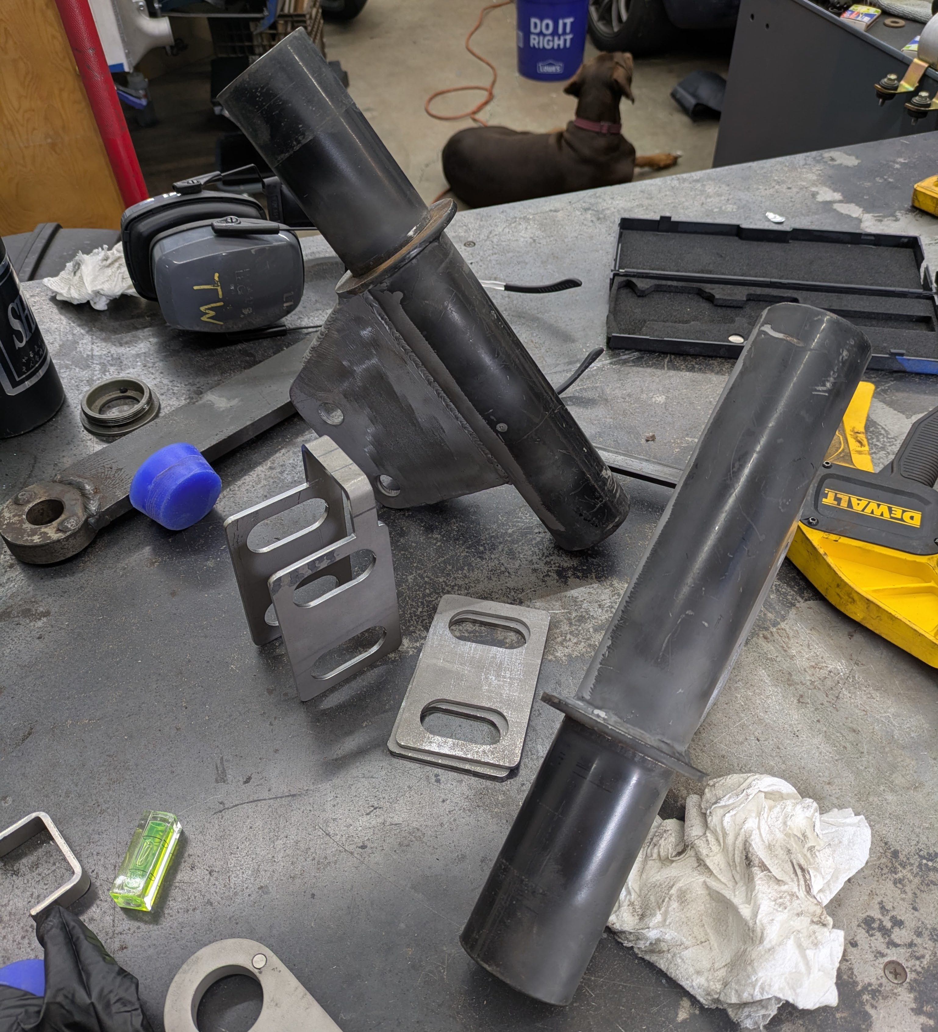
With the fronts done, we now have to address the rears. My various purchases had left me with 4 front housings, and two of them are going to turn into rears if I hope to have a suspended car. I decided the silver pair from Garrett was going to be the one to sacrifice.
After cutting of the majority of the ears at work on the vertical band saw, I spent a night grinding out plug welds on the brake line brackets and cutting off ears in order to get the housings to fit around all of the rear arms.
I attempted to clean them up even more on the lathe, but the interrupted cuts on the welded material went poorly (I.e. the toolpost was trying to ollie), so I decided to cut my losses. I learned during my difficulty cutting the weights off the rear subframe that perfection when you don’t have the right tools is a trap, and you are better off stopping early if the objective has been accomplished than try to go all the way and end up with a result you heavily dislike. While the rear housings aren’t perfect, they are functional and will be pretty enough once finished. A toolpost grinder would be the way to do these, but we don’t have one.
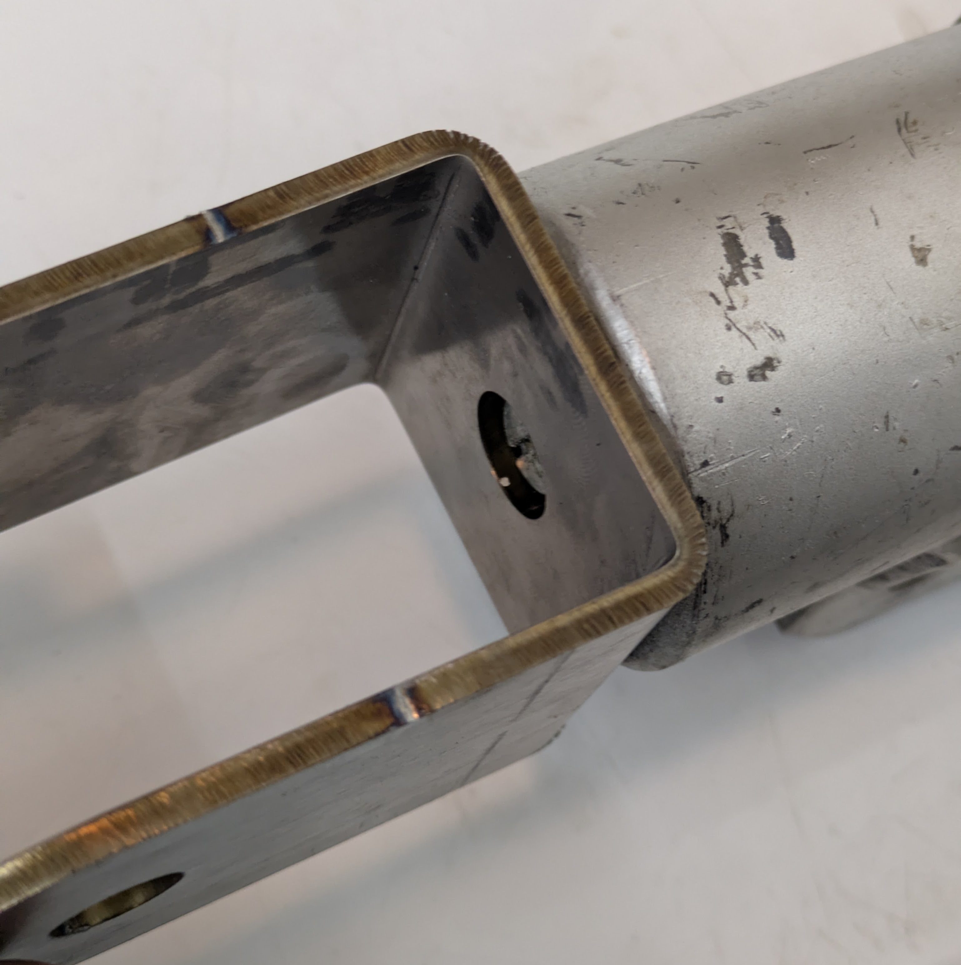
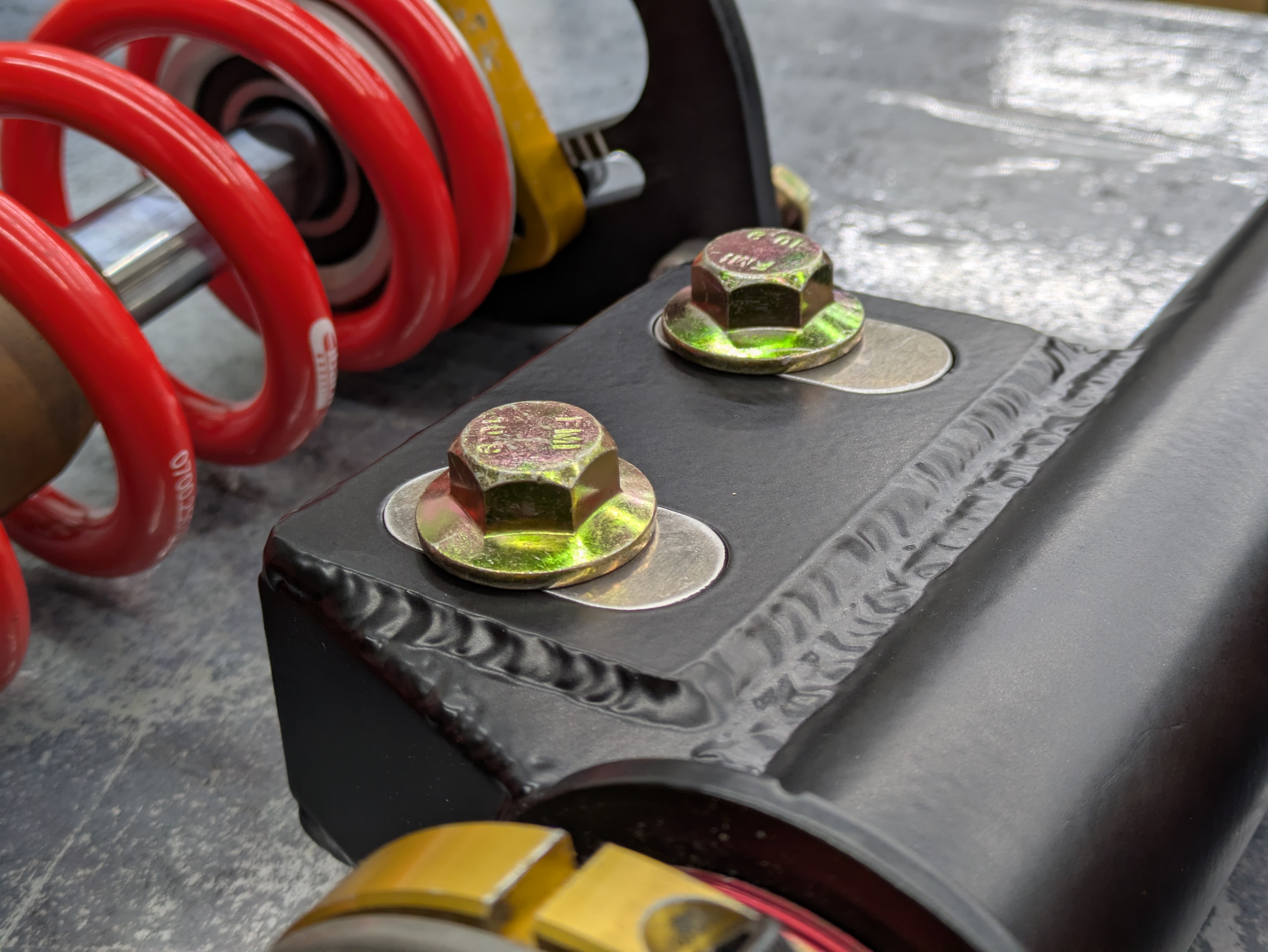
The Z32 lower rear fork geometry was ripped straight from the Bilstien rear housings I got from Garrett. I cross checked the distances with the Veilside housings, and they were in agreement. I wanted a nice beefy mount that welded nice, so SendCutBend shipped me a 4130 fork, pre bent with the aligned holes for the lower bolt and the access hole for the compression adjustment. Once again, so good, so fast, and so cheap.
The rears were ready to go before the fronts (breaking chronological order), so I dropped them off with Ethan to get them burnt together. These went to powdercoat as I was in a pretty good cycle of biweekly pickup/drop off with my guy.
Earlier I had shown off the machining of the Megan rear spring perches to fit my designed height stack for the rear tophats. While that part fit perfectly, I was annoyed that the perch was actually designed for a 60mm ID spring, not the 2.5″ that I had. While it probably wouldn’t have rattled (or mattered), I was already so deep in the sweat equity in this project that I just decided “FUCK IT, I’LL JUST MAKE MY OWN”.
I drew it up to use the same 4″ material from the tophats as I had JUST enough left over to make a pair/
These were a similar manufacturing process to the rear tophats with far less material removal and dimensional criticality. They got finished over a few lunches and breaks when I had the time.
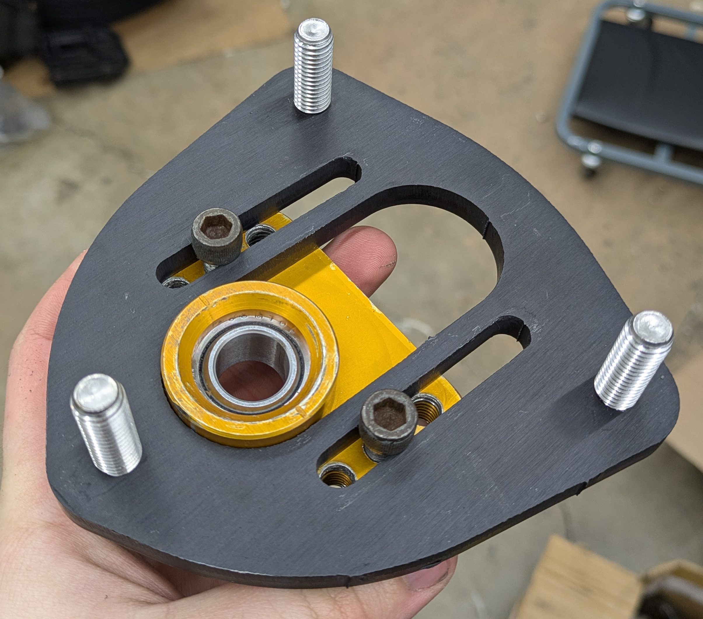
As I was rapidly approaching final assembly, it was time to focus on some of the sub-assemblies. The front radial bearings were noisy and shitty, and play a critical role in making sure the suspension doesn’t bind when you turn. New double sealed bearings. Cheap, easy, and less than 5 minutes to install.
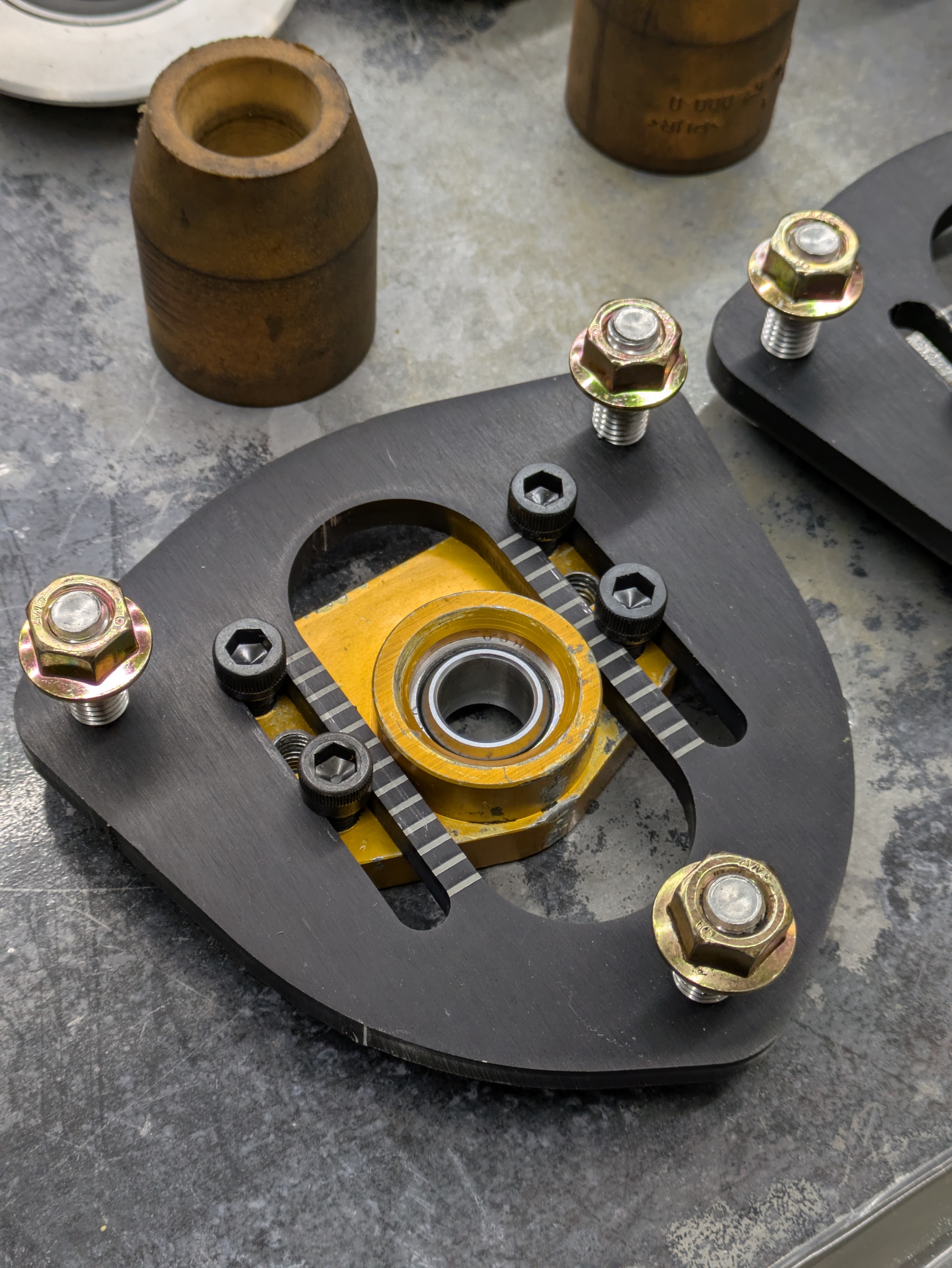
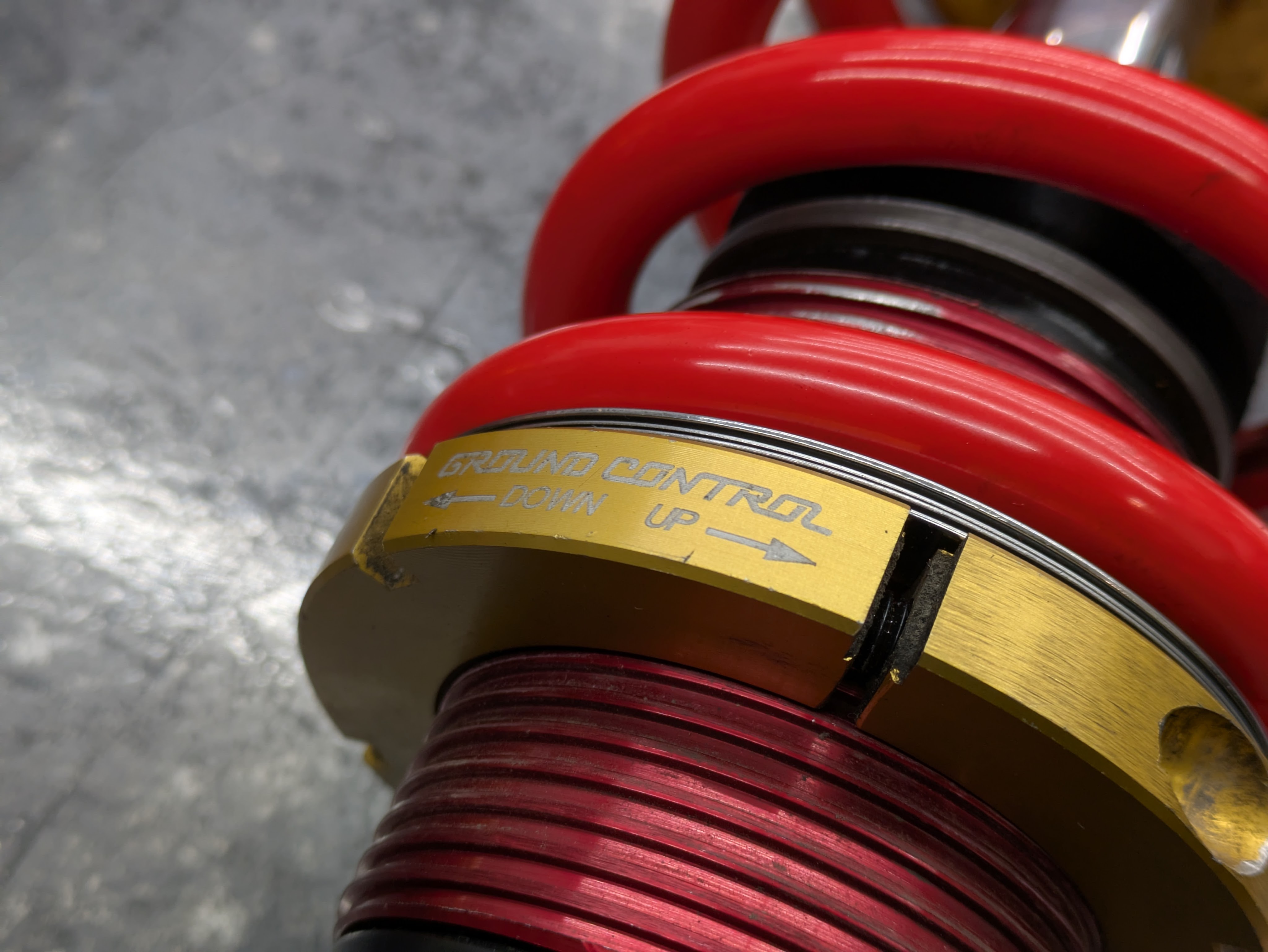
If I was going for 100% credit here, I wanted to at least match all of the features of the existing coilovers on the market. Many of them have etched or engraved marks to reference when adjusting camber evenly side to side, and my blank laser cut ones were missing that detail. Work has a fiber laser for engraving parts, and we had settings for anodized aluminum, so I 3D printed an etching jig to locate the parts identically.
The fixture made it super simple, and while these are going to get torn up when bolts are tightened down on them, they are still legible and useful. I permanently installed the SHCS “studs” at the same time, and with the addition of new Aurora sphericals pressed into the bearing plate, we had completed front tophats.
The front housings were the last piece to come back from powdercoat, and I was both eager and nervous to figure out if I had calculated my tolerance stack correctly. This was my first time designing around powdercoat, and it’s inherent inconsistent nature was spooky. It worked out in the end, and god damn were these things flush. Couldn’t have asked for a better fit.
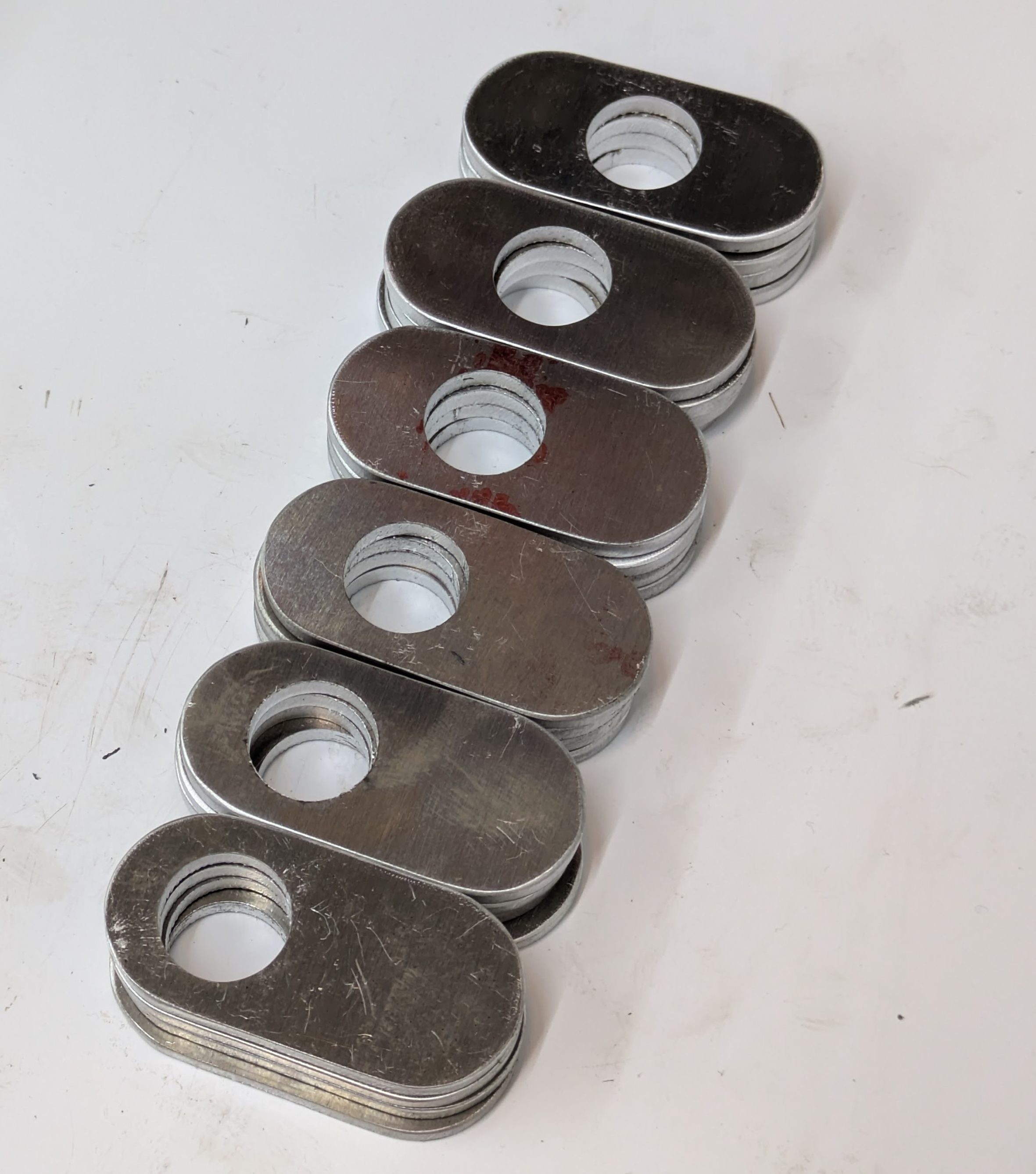
The adjustment shims had showed up many moons ago with the tophat plates. 0.125″ 7075 Aluminum with 2mm increments from 0-10mm. Super overkill in terms of granularity of adjustment, but when wheel fitment is this tight, you need those options.
Just because I made my own shims doesn’t mean they were perfect out of the box. I spent some time on the grey wheel smoothing the cutting edges down and removing the ingress/egress pips. I debated anodizing these, but after a group discussion of how fixturing them would work and how cheap they are to remake, I decided if they corrode or get shitty, I’ll just replace them. This isn’t a 4 season car anyway.
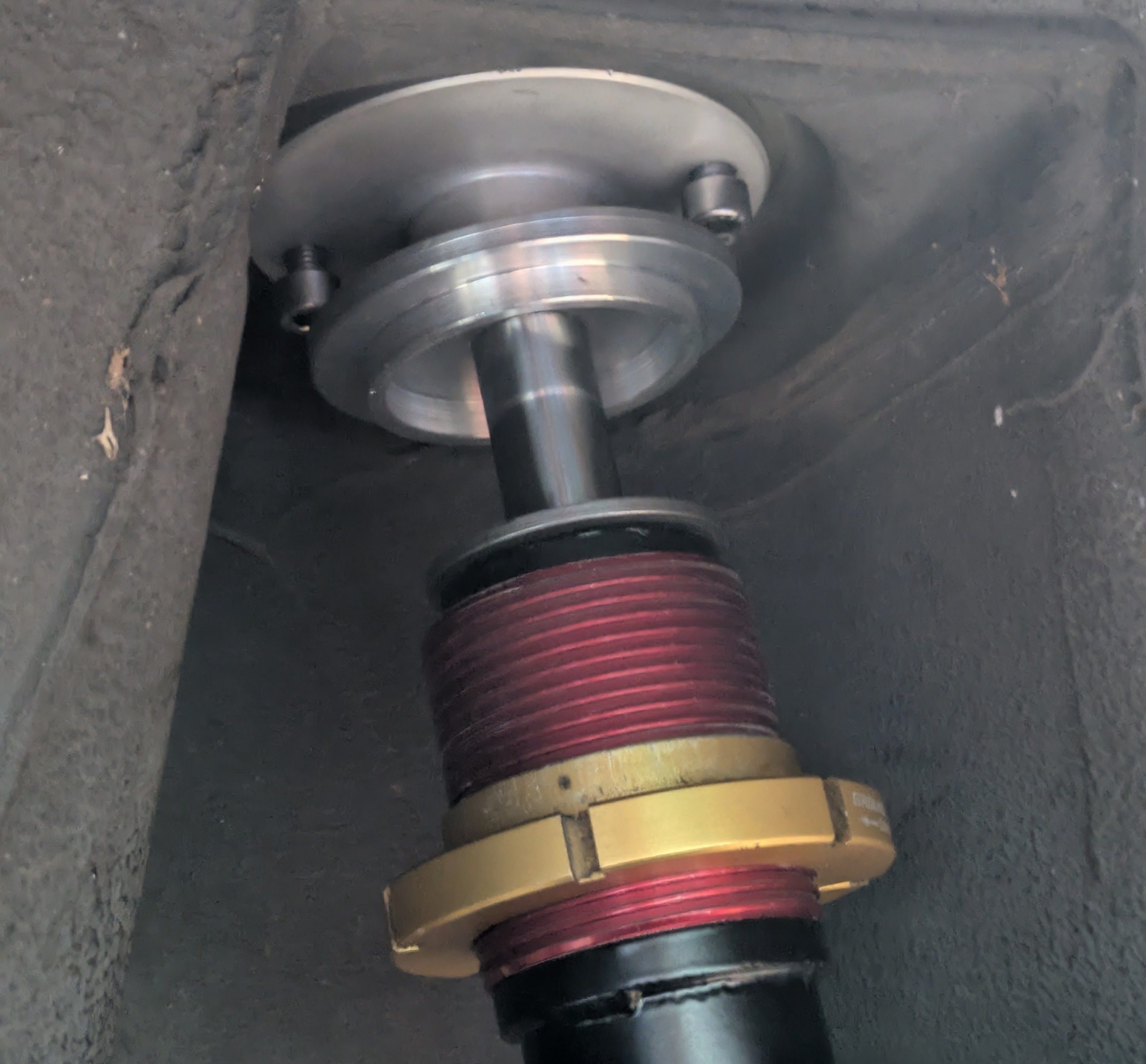
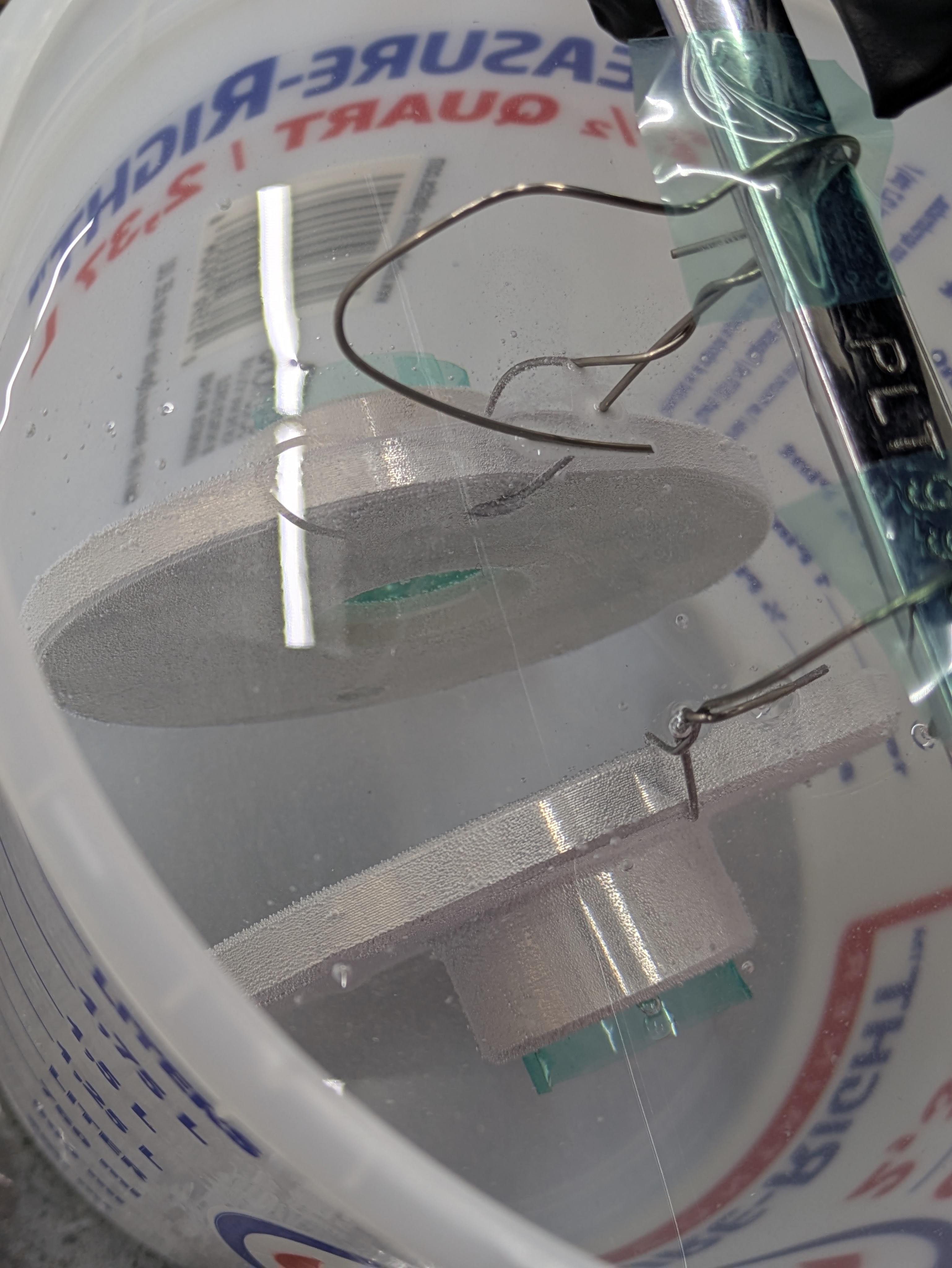
With all the sub assemblies finished up, I started validating geometry, primarily bump travel to ensure that I hadn’t made a gross miscalculation. Once I got the rears back from powdercoat, I quickly put one together with everything minus a spring and bumpstop to check where I was at for bump travel. As you can see, we can go REAL deep, impractically so. The side skirts would be deep in the ground, the springs would be completely bound, and the chassis is at risk of hitting the ground, but I can work with this.
The front was a little more complicated, as I not only had to set bump travel, but I had to figure out where my camber shims were going to land so I knew what adjustment and space in the wheel well I would have. What ensued was a delicate evening of trial and error, balancing clearance between the wheel/tire and strut, as well as the fitment to the fender.
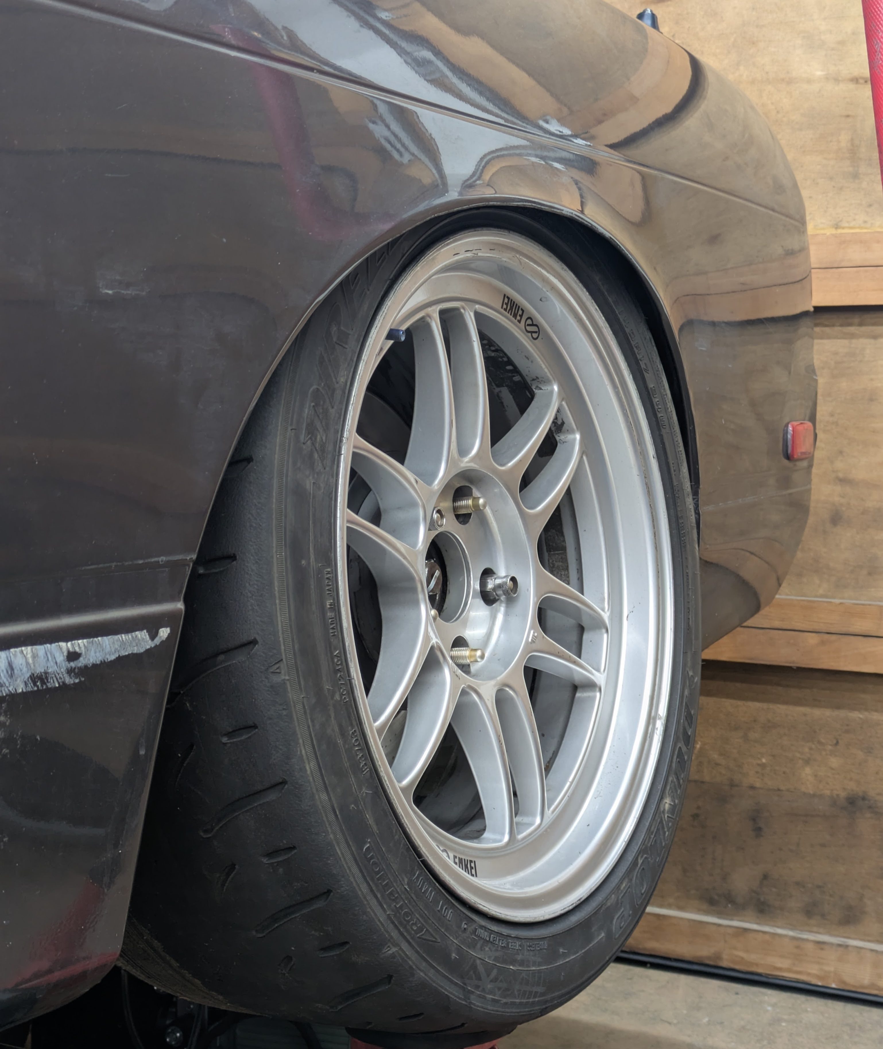
The 255/40/17 tire and 17×9+22 wheel combo that I had selected turned out to be quite the challenge to fit. With the wheel jacked up for bump travel check, it was clear that Nissan was not considering such a large wheel and tire package when they designed this car in the ’80s. There is a very good chance that I will have to take an air hammer to the tubs, which hurts me inside, but I’d rather have have dents and cracked paint than rub hole into my engine bay (already have one). I refuse to put traditional tubs on the car as everyone seems to regret it, but I am open to the idea of a Group A style wheelhouse section and raise when I paint the car in a few years. I’m hoping a bit of hammering is all I need, but we will need to test for that first.
Back to the suspension, I settled on a 4mm offset for the camber shims with a 2mm/6mm pill in the strut. This got the tire as close to the spring as I was comfortable with while not poking the wheel into the fender. Wheel spacer is a topic for a later article as they played a pivotal role in this dance of getting zero brake clearance wheels (RPF1s) over gigantic brakes (Evo 9 Brembos). I’ll just say it was a long night but roommate Will and I eventually found a happy point where everything fit.
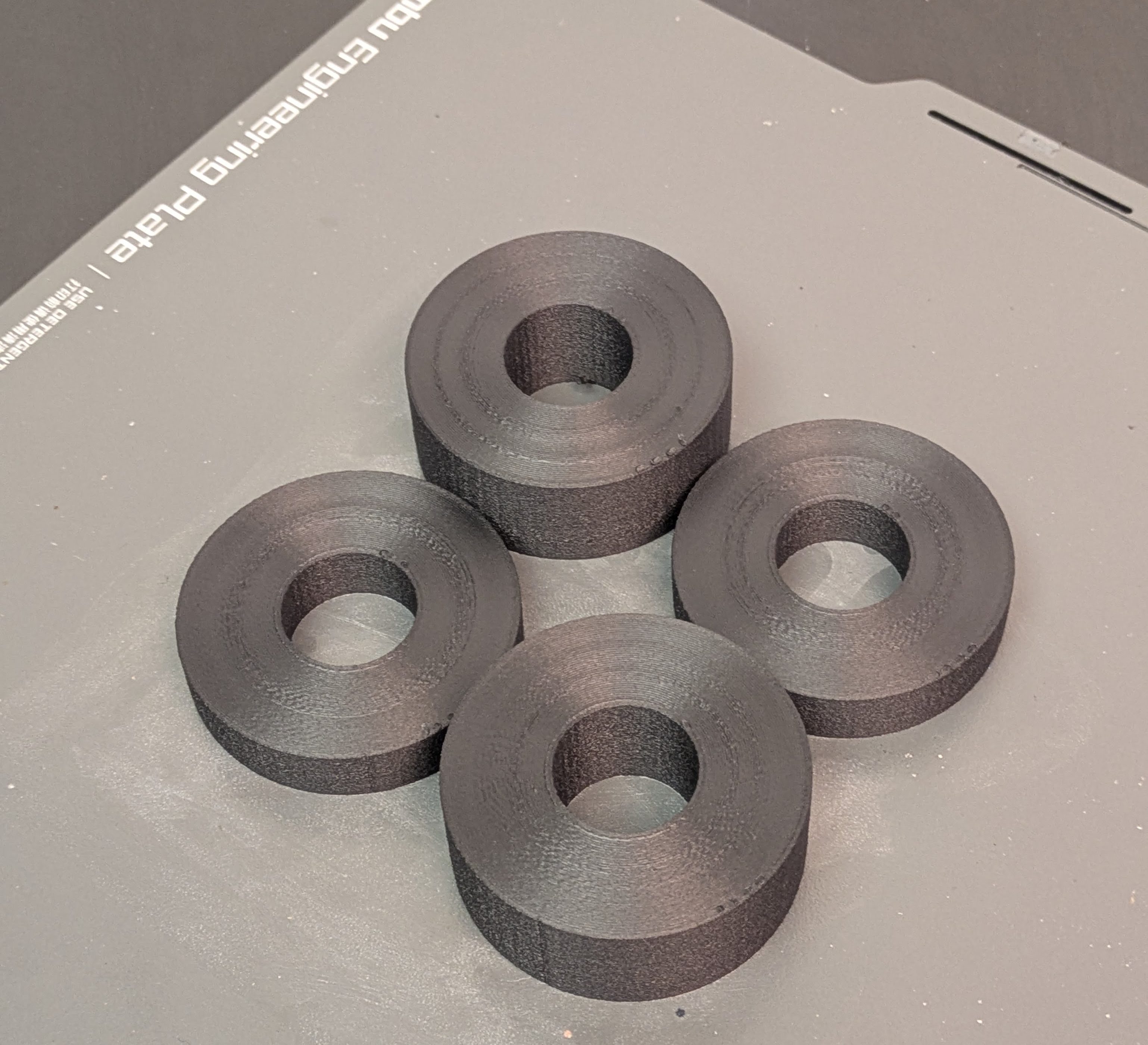
With the wheel clearance figured out, it was time to finish the bump stops out so they would actually be functional in stopping the wheel from contacting the chassis. After measuring and going through all the bump stop options I had accumulated over the years, I settled on a relatively soft bumpstop front and rear, since I’ll be in them a lot given the geometry of this car and I wanted a really progressive transition. I ended up needing a lot of bumpstop packer in the front to keep the wheel off the chassis, which makes me a bit bummed since I’ve enjoyed gobs of bump travel in my Mazdas, but that’s just how it has to be with this car.
These were printed since I had a custom dimension I needed to accommodate for, and I had the printing capabilities to do so. These packers are made out of PA6-CF, a carbon reinforced Nylon that I have come to really appreciate for it’s great printing characteristics (layer adhesion, decent dimensional stability, repeatability once it’s dry) and its mechanical properties of being strong as shit and machinable with sufficient wall loops.
Quick intermission for the last process: anodizing the rear spring perches. We already did the rear tophats, and the setup was out again anyway for another batch, so when in Rome.
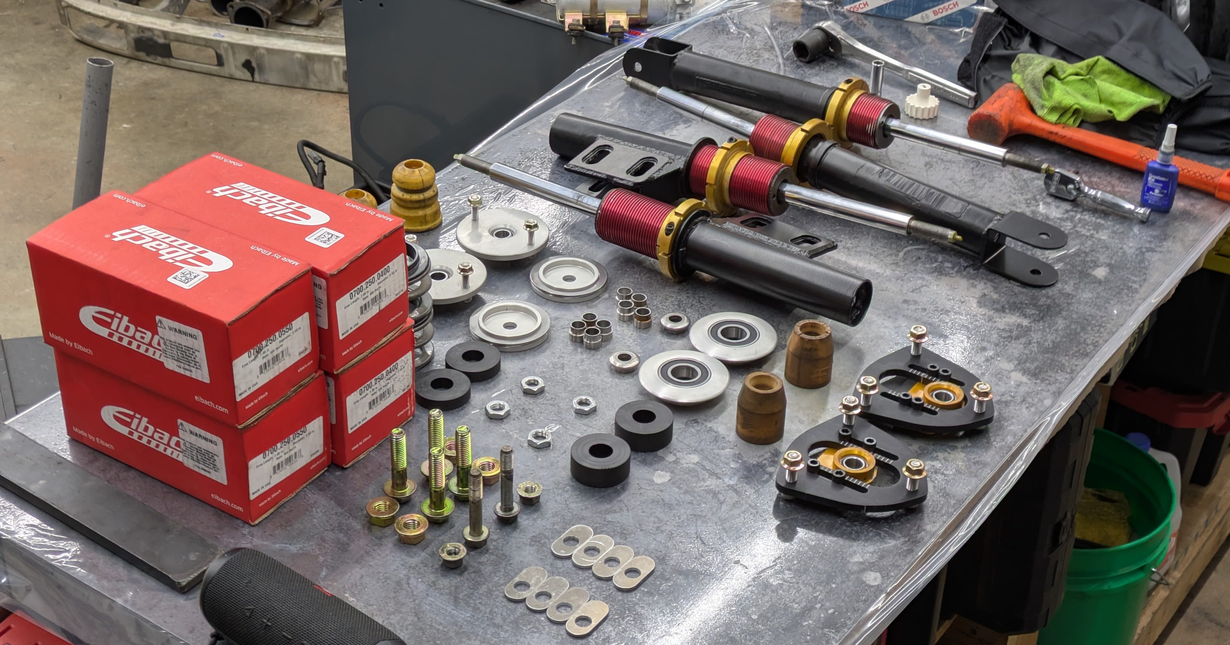
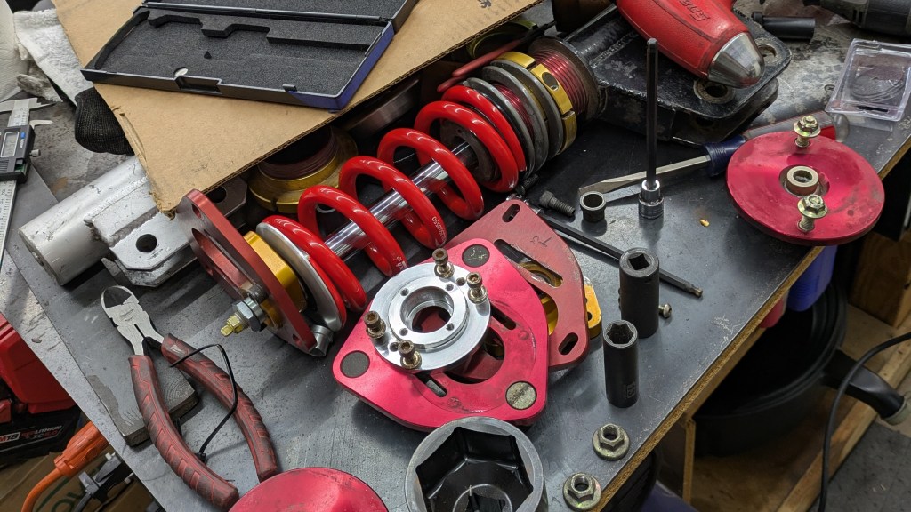
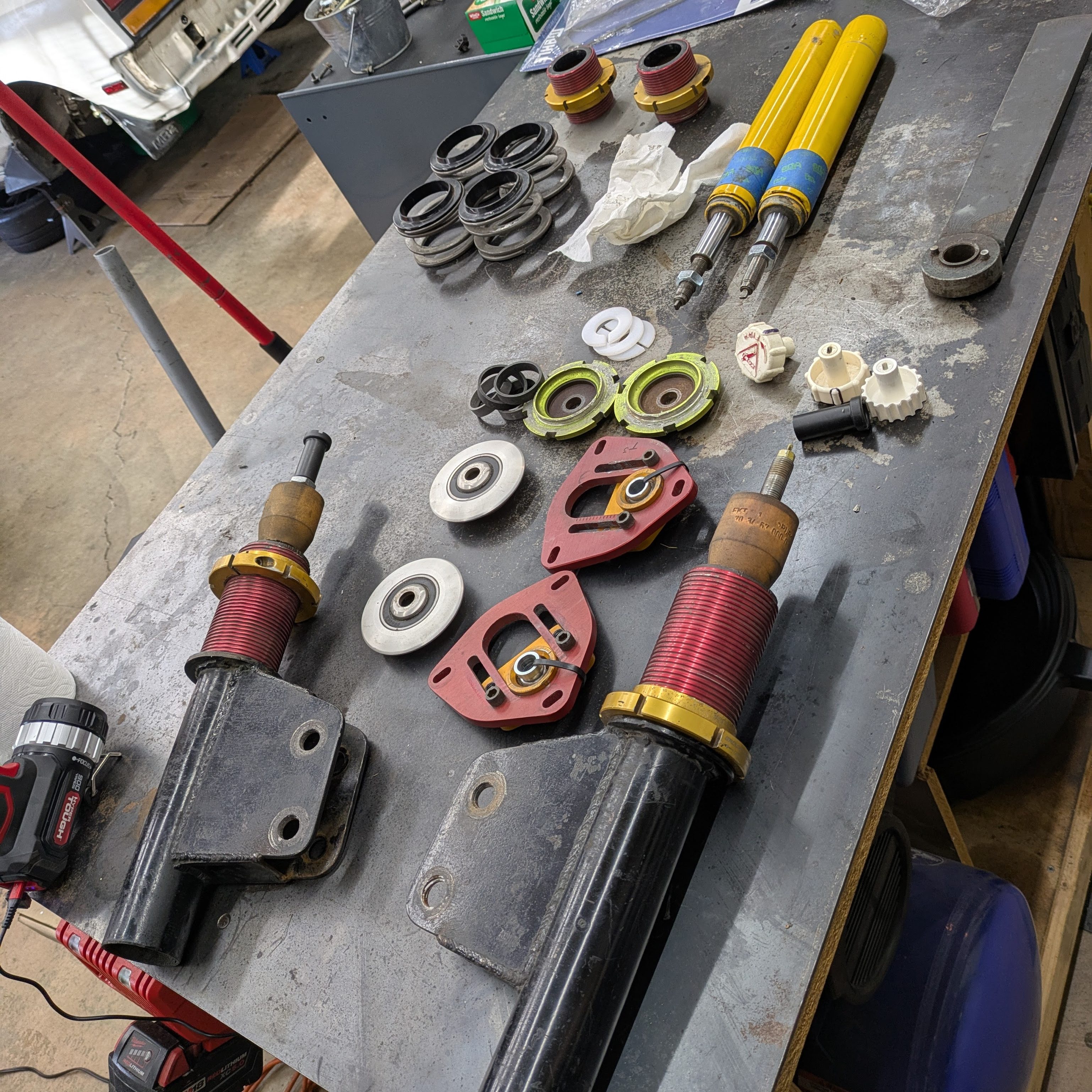
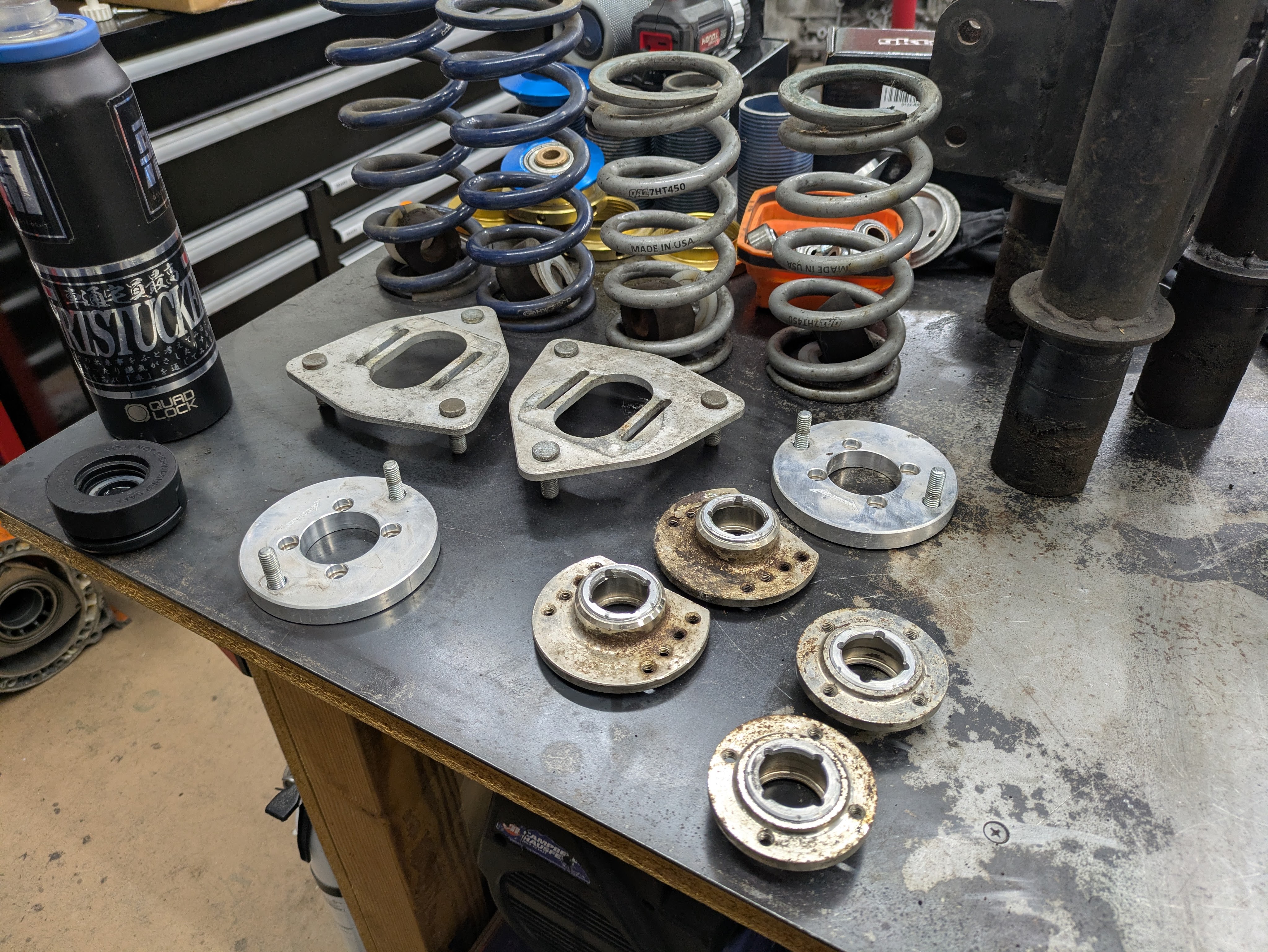
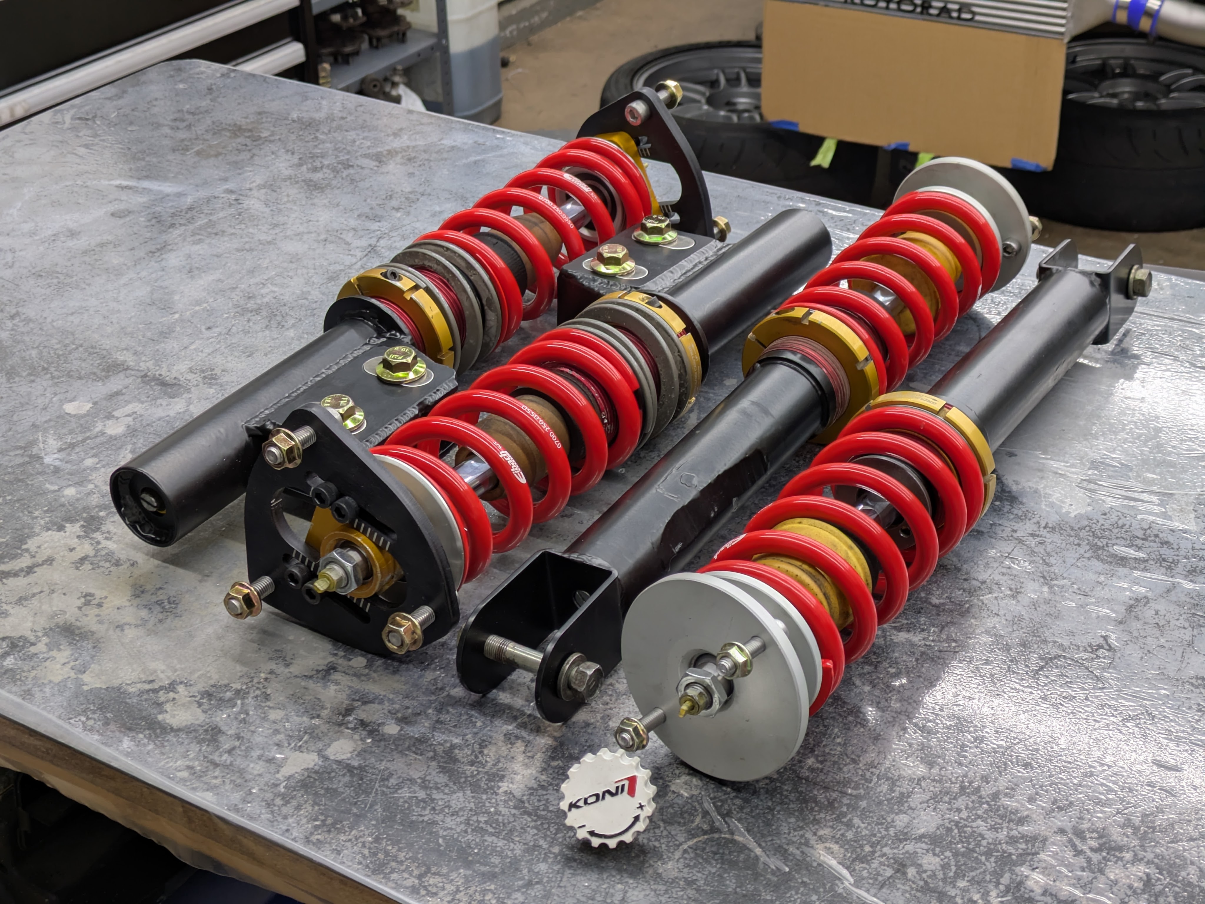
With the final parts finished and everything back in one place, it was time to assemble them for the final time, but not before taking a loadout/layout photo. I don’t even want to think about how many hours of my life are on the bench in this photo. If there is one regret from this build/rebuild, is that I only kept track of the dollars and not the hours.
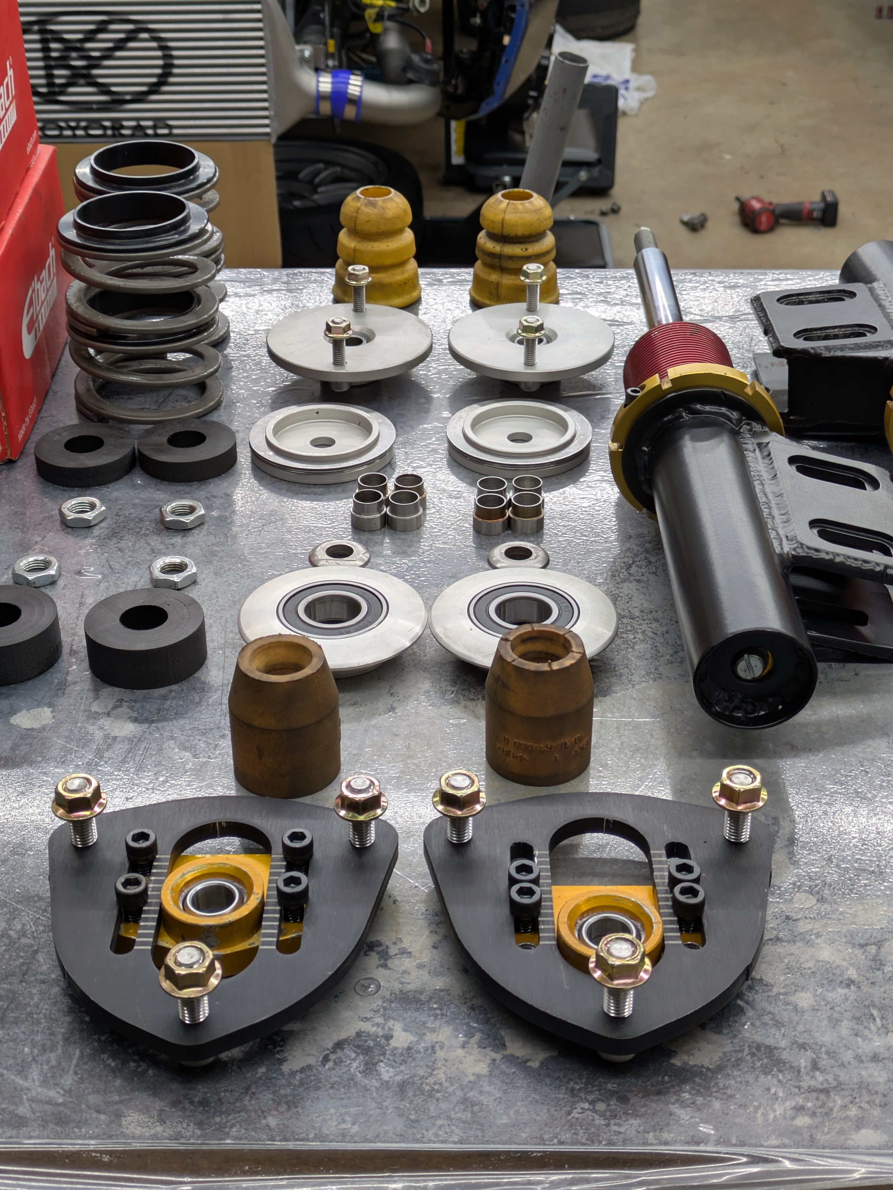
I wish I got more of a top down shot, but I started assembling these at 10PM on an already long Saturday, and I just wanted it to be over with.
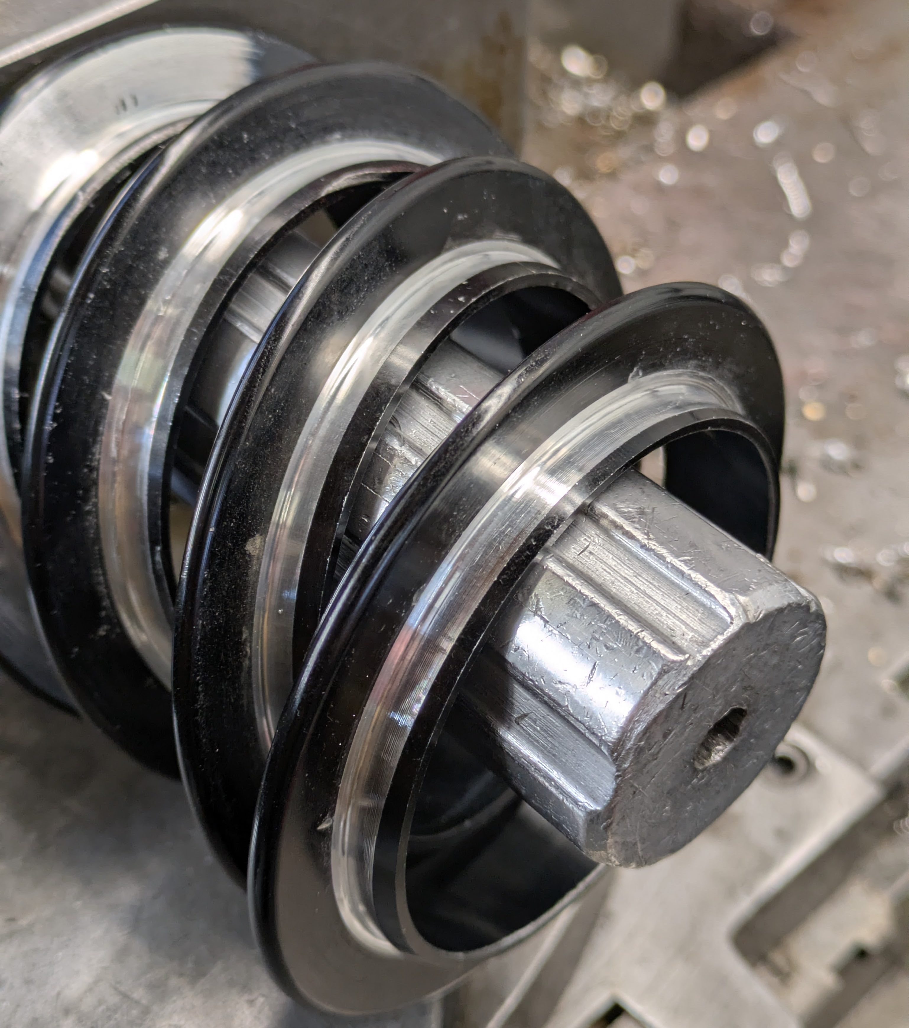
I mentioned the inclusion of Torrington bearings earlier, which are sandwiched between the spring and perch to prevent spring binding under compression. The front doesn’t need one as it already has a radial perch, but the rear got a pair. Just make sure the coilovers have covers if you do these. Even dirt and debris in the dry will absolutely murder these.
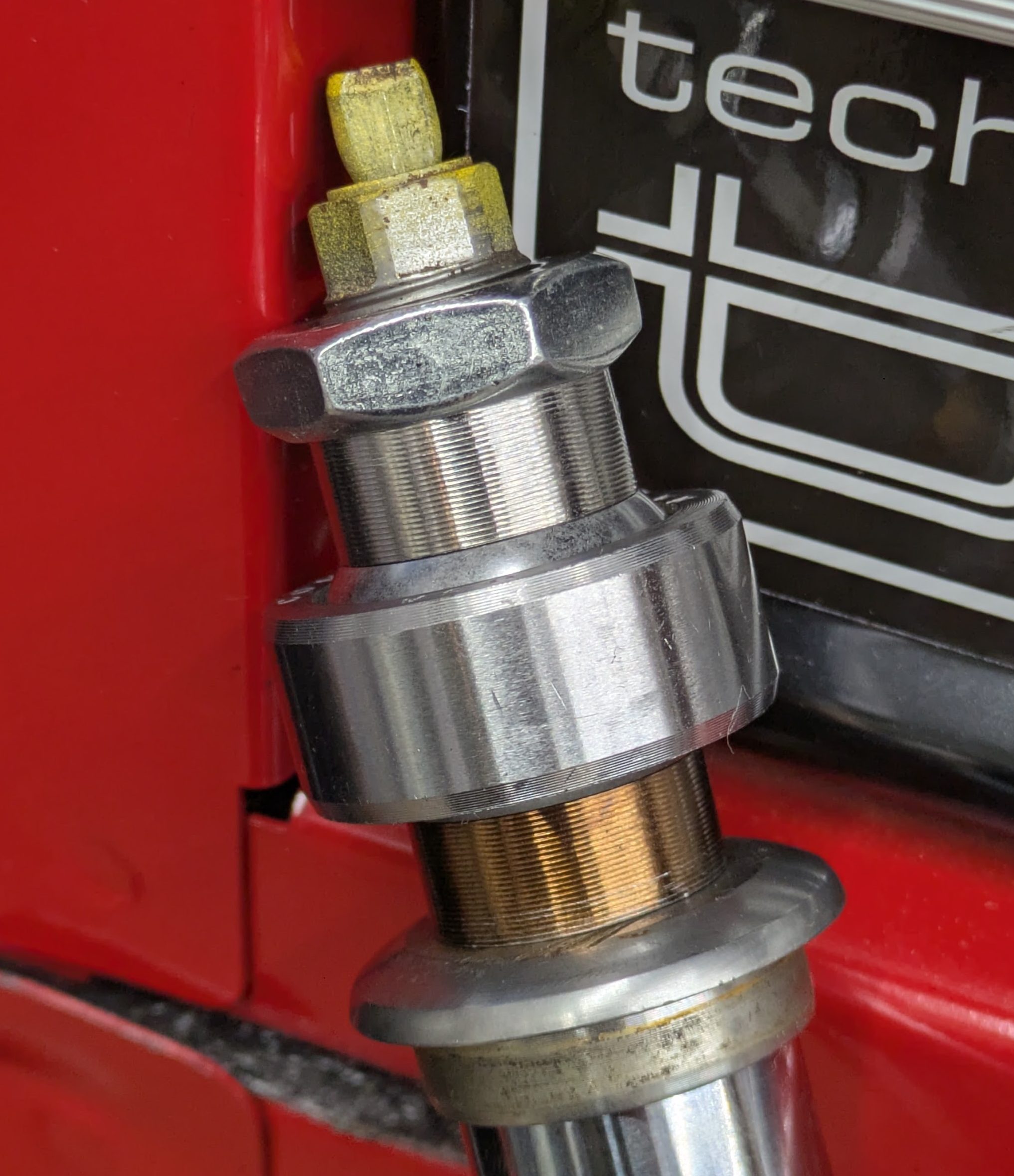
The final assembly begins with installing the struts in the housings. Extremely simple job of shove in tube and tighten gland nut, but I did add some Gaffer tape around the strut to center it and prevent any chance of misalignment. Thought about overcomplicating it with a printed sleeve, but tape works great. The gland nuts were torqued down with antiseize, but not before installing the Ground Control sleeves as they are captured by the lip of the gland nut.
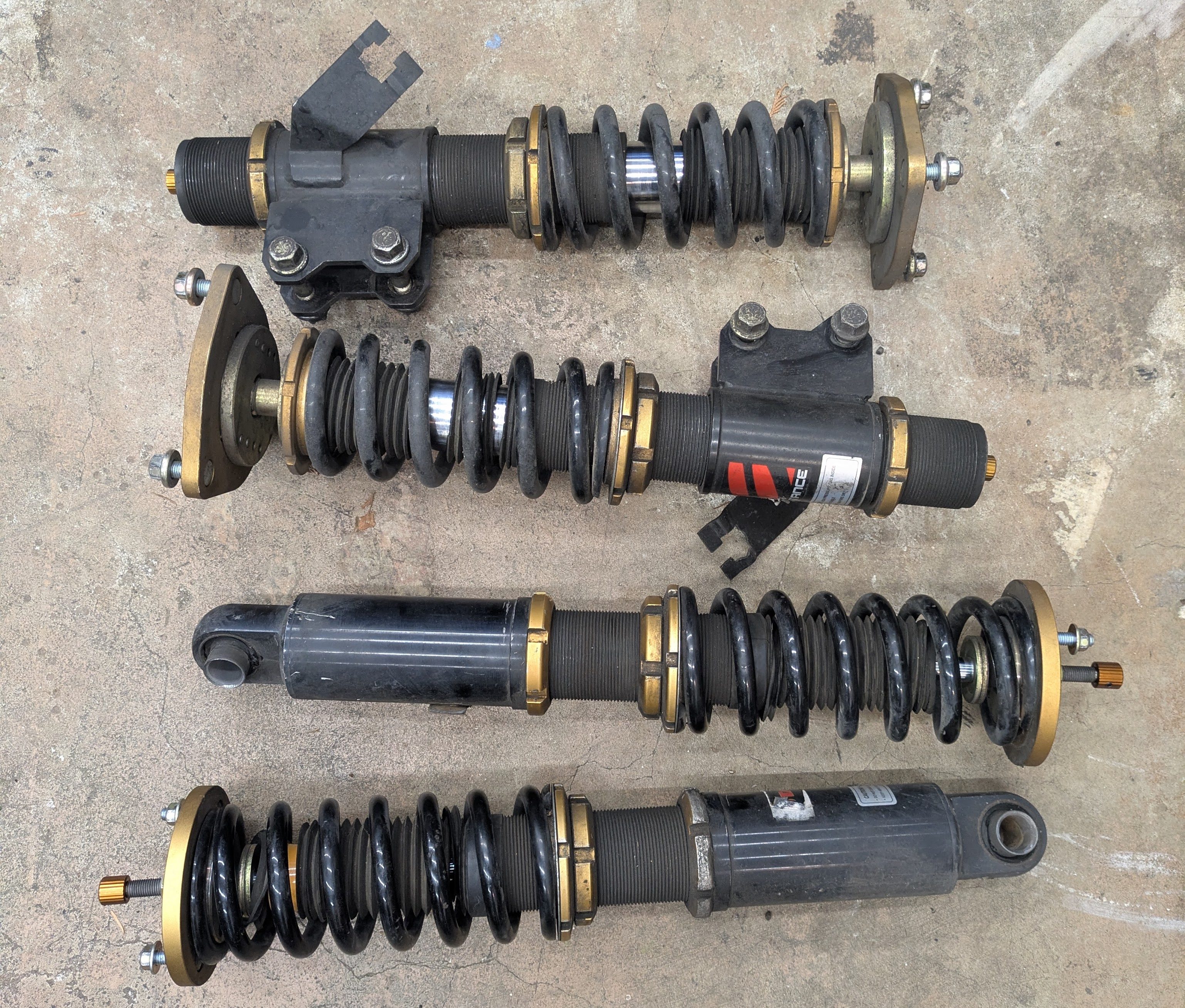
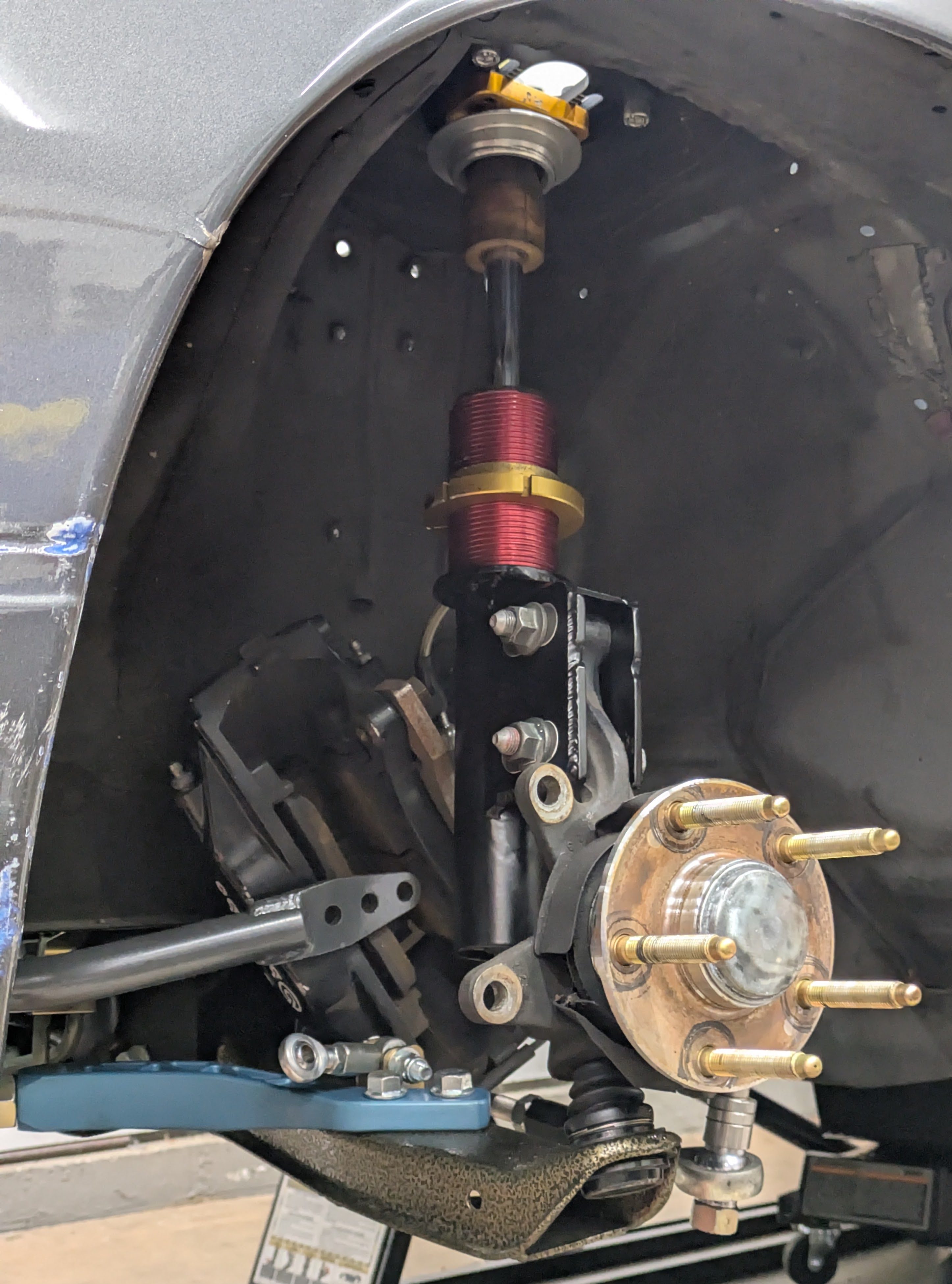
I spent the final part of my evening in a flow state, stacking the shocks together until I had a complete set of coilovers sitting on my bench. I’ll just let the photos talk.
I’m proud of these. Like really proud. Sure, it doesn’t have the jewelry properties of MCS or Penske, but 80-90% of the performance for half the money, I’ll take it.
Throughout this project, friends and I referred to these as the Sweat Equity Shocks. Because between the actual financial investment, and if you had billed out my time at an appropriate rate, these are more expensive than a set of MCS 2WRs. Is that mildly embarrassing? Yes. Do I care? No. I think these have some distinct features that make them better than MCS, and the fact I was able to build a set of coilovers with my hands (and two degrees) as a pretty good validation that I do kind of know what I am doing.
I will say that while immensely rewarding, this project was dodging comprise at every turn, and my only way out most of the time was the fact I have a machine shop at my disposal and the experience to use it. I don’t think this is practical if you don’t have those tools and resources. As said, even if I could do the designs for free, these would be more expensive than MCS if I had to pay for the manufacturing.
At the beginning, I was so hung up on the fact that housings were the part that this project hinged on. When ironically, at the end, all housings were to me were tapped steel tubes with a bottom plate welded into them. If I coughed up the money for the M54 gland nut tap and had someone with an old set measure the lengths, I could have very easily have made my own.
I was originally going to title this post “Red Vs Blue”, derived from the red and blue threaded sleeves of the respective sets. I hoped to have my “for sale” set of coilovers done at the same time to show, but unfortunately, they required a few more parts that I haven’t had time to make. I’ll be finishing those up soon to recover some of the costs of this whole damper project, and I’ll post about them somewhere when they are done.
So there it is. There are more hours invested on that table than any other project on the whole car. But I wouldn’t change a damn thing.
Until next time.
