
Welcome to: everything in between engine/trans install to first start. This one is long long, so be prepared.
After the engine install, my attention turned to the next largest item in the garage, which was the radiator/clutch fan/fan shroud assembly. These are best installed as a single unit, especially the fan and shroud, as there is no room to maneuver them in after the fact.
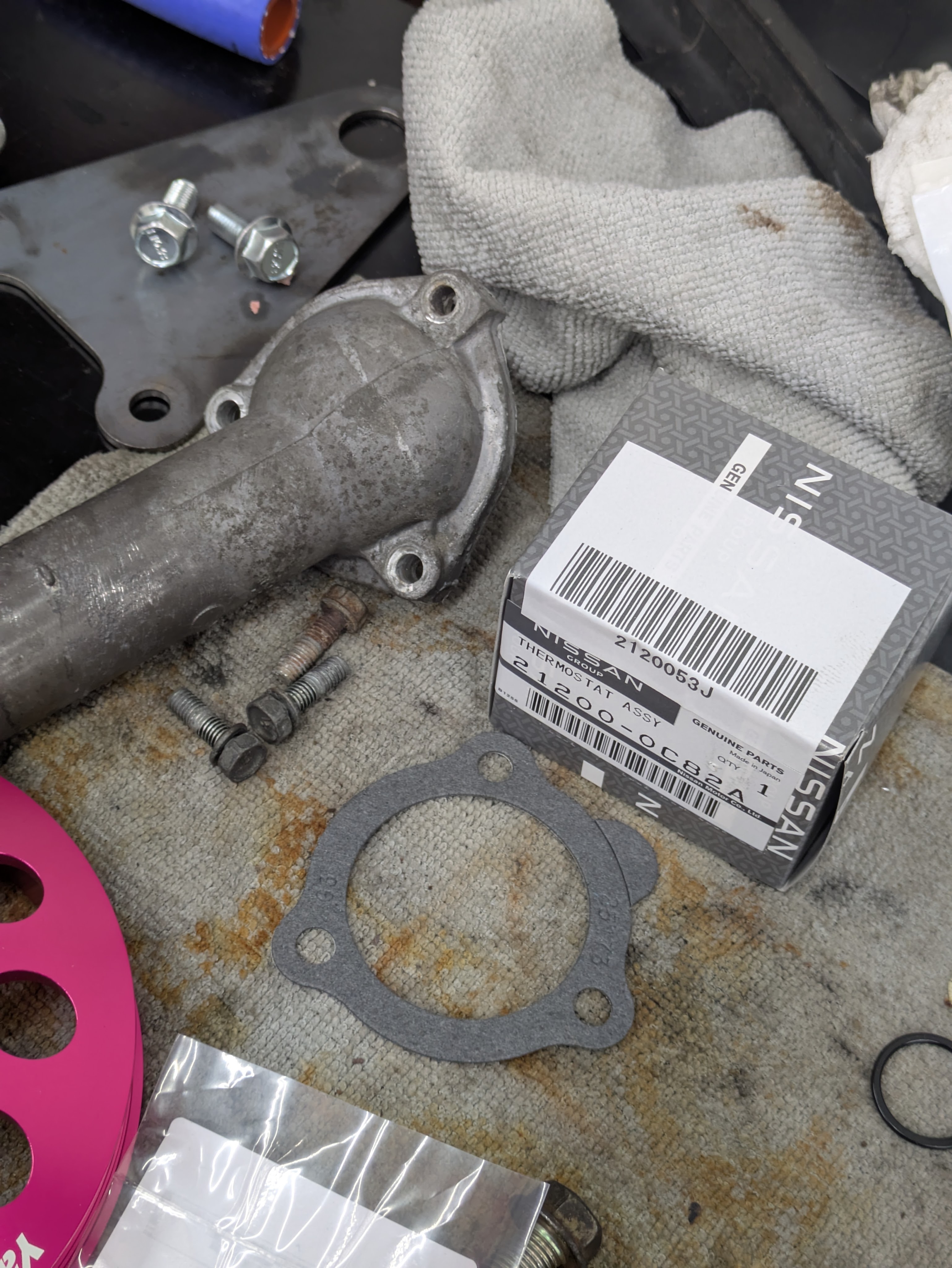
While I wanted to get the the thermostat and water neck on before I put the motor back in, I was missing a gasket and hated the idea of only RTVing it. While I didn’t let it hold me up, I did throw it in before major work started. As always, new OEM everything.
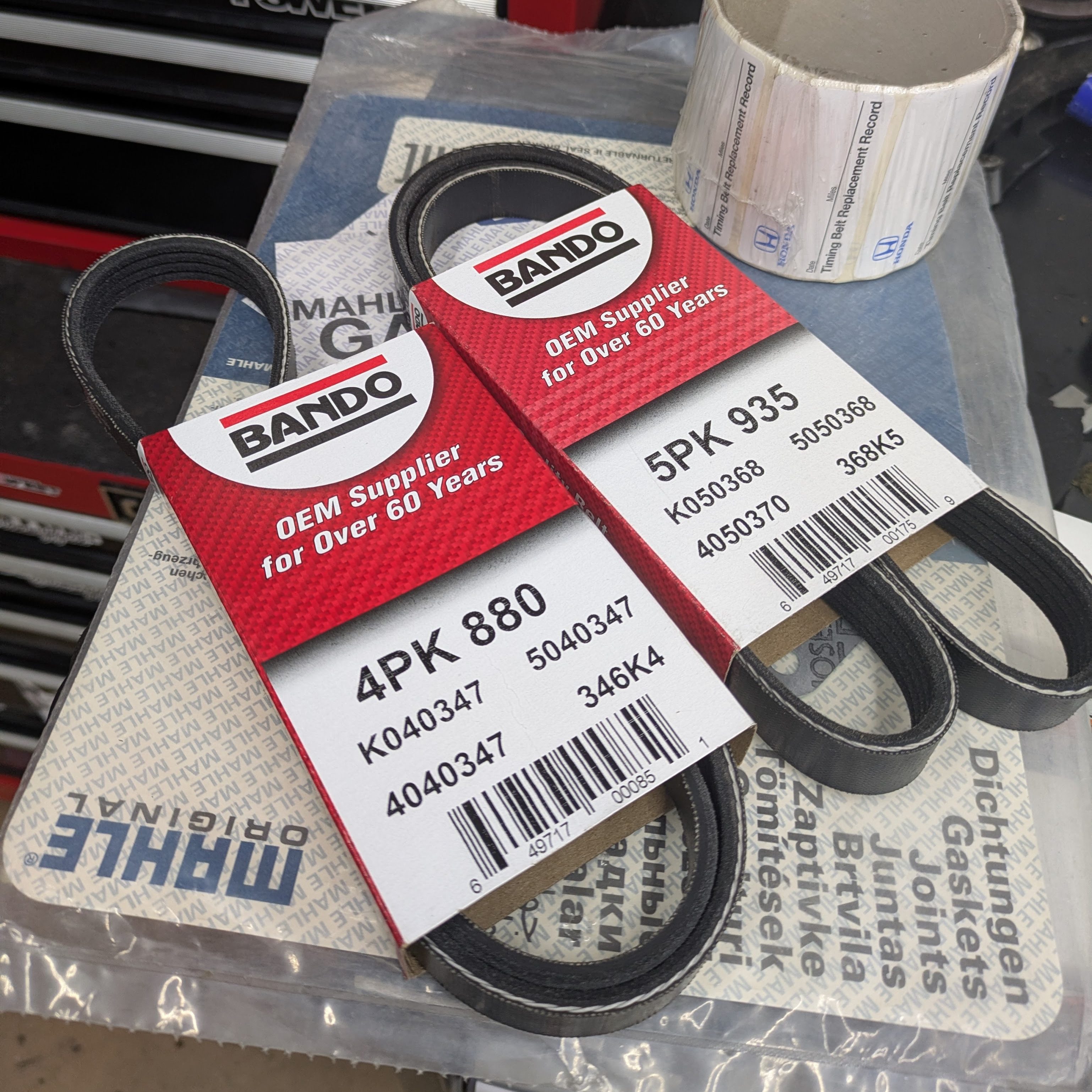
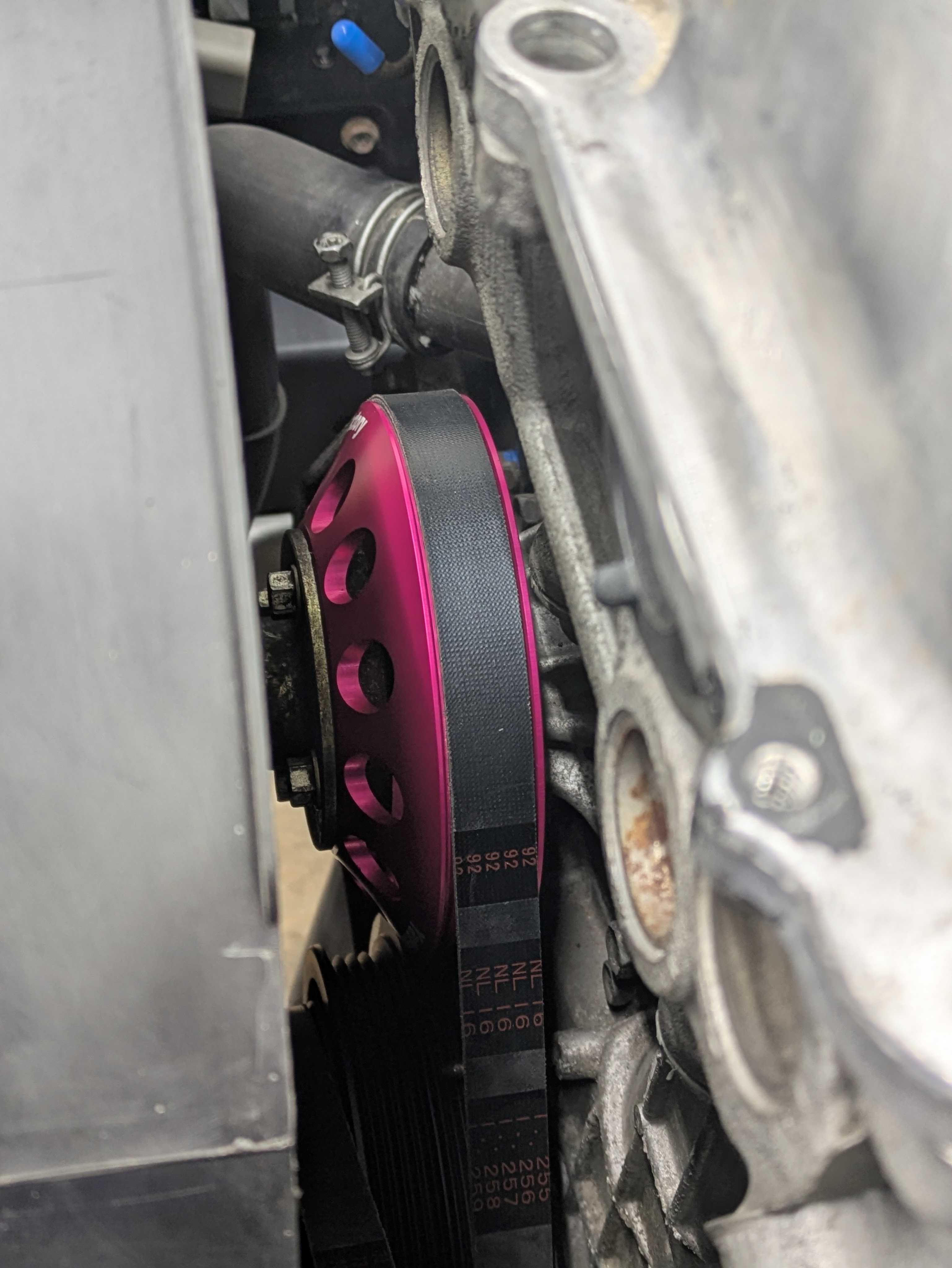
I threw the water pump pulley and belt assembly on before slotting the radiator in. I needed to change to a larger diameter pulley to reduce cavitation, and in keeping with the early D1 theme, I felt like the Yashio Factory water pump pulley was appropriate for both aesthetics and function (and I was already making a Nengun order). I debated selling it in favor of a black Touge Factory one (that were out of stock at the time), as I was worried the pink would clash with the rest of the engine bay theme, but it is so out of the way and hidden by the fan shroud that it is more of an Easter egg for those that look. TF may be back in stock, but the pink is staying. The belts are brand new Bando in the OEM size for both the power steering and water pump/alternator (the nice advantage of most of the enlarged pulleys on the market is that they can still use the stock belt size).
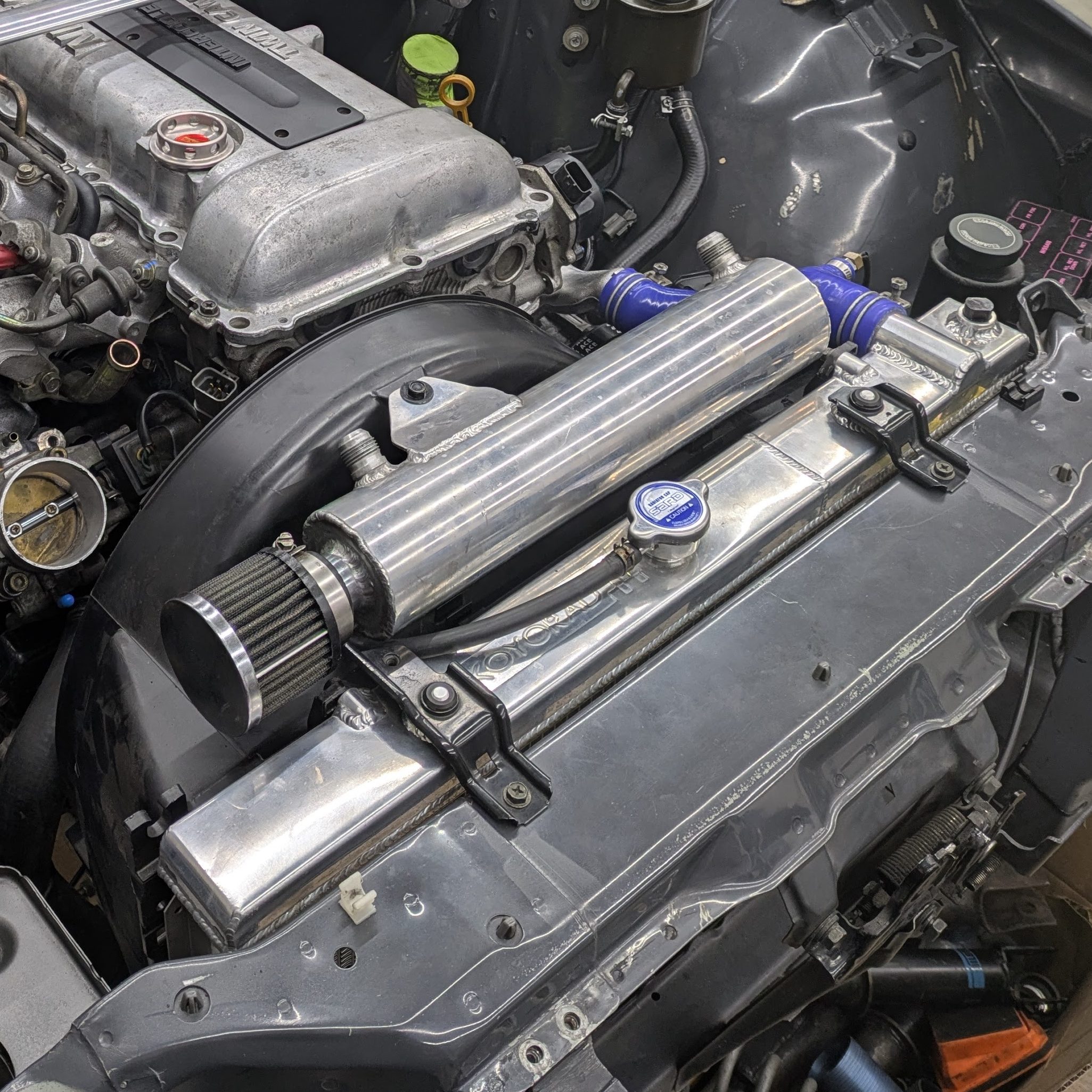
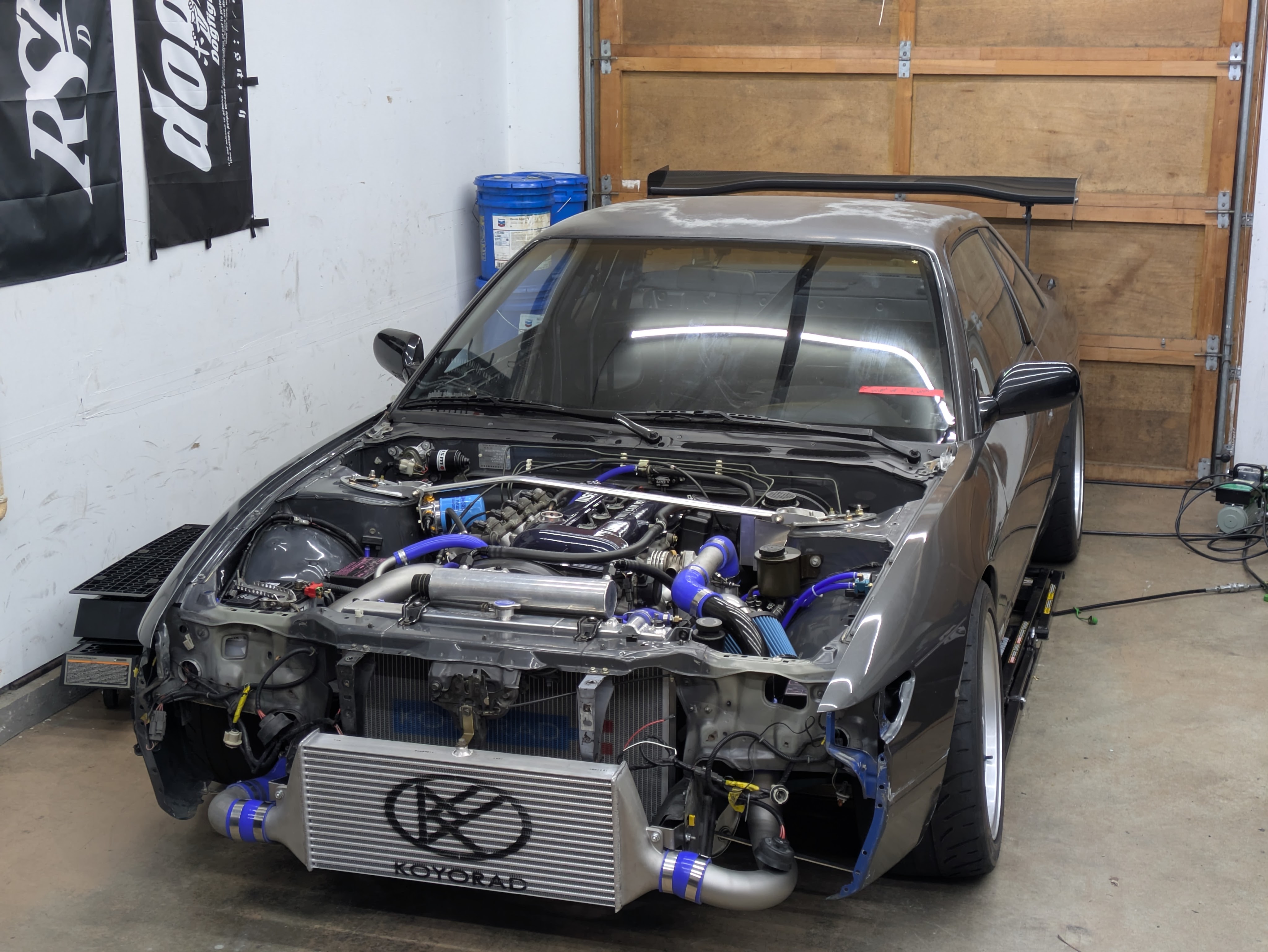
With the front drive mocked up, the Koyorad N-Flo that came with the car, the clutch fan, and absolutely massive OEM Nissan shroud could be reinstalled. No notes, just a great radiator with a fan setup that ensures that this car will pretty much never overheat.
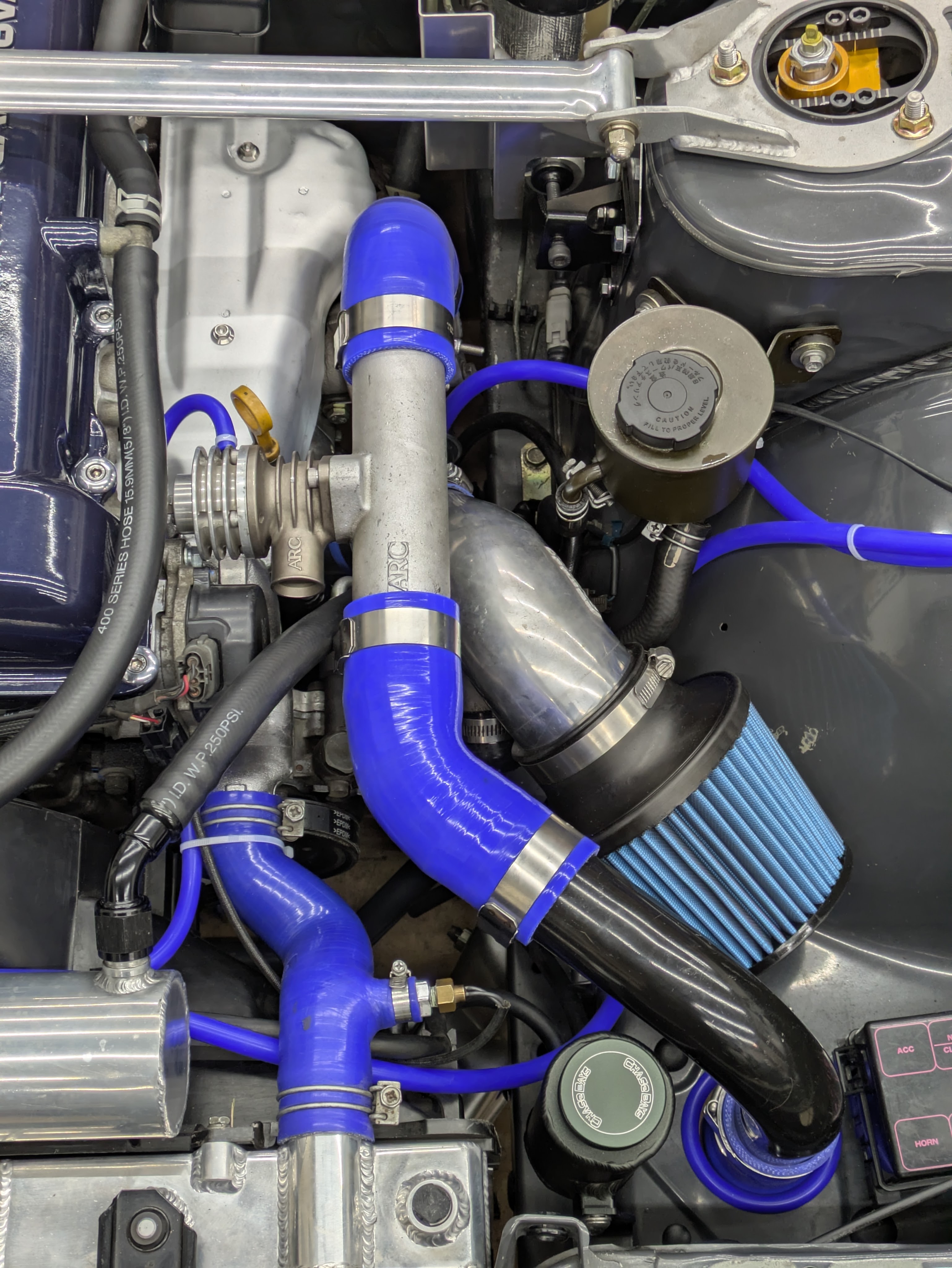
The catch can does have many notes. I knew I wanted an over-radiator catch can as I think it is a great visual addition to the bay, as well as an out-of-the-way and underutilized region. The OG Kazama ones are pretty much exclusively YAJ gambles at this point, and the GKTech ones leave a little to be desired cosmetically and functionally (not that Kazamas functioned great either). So to say I got really lucky on this purchase is an understatement.
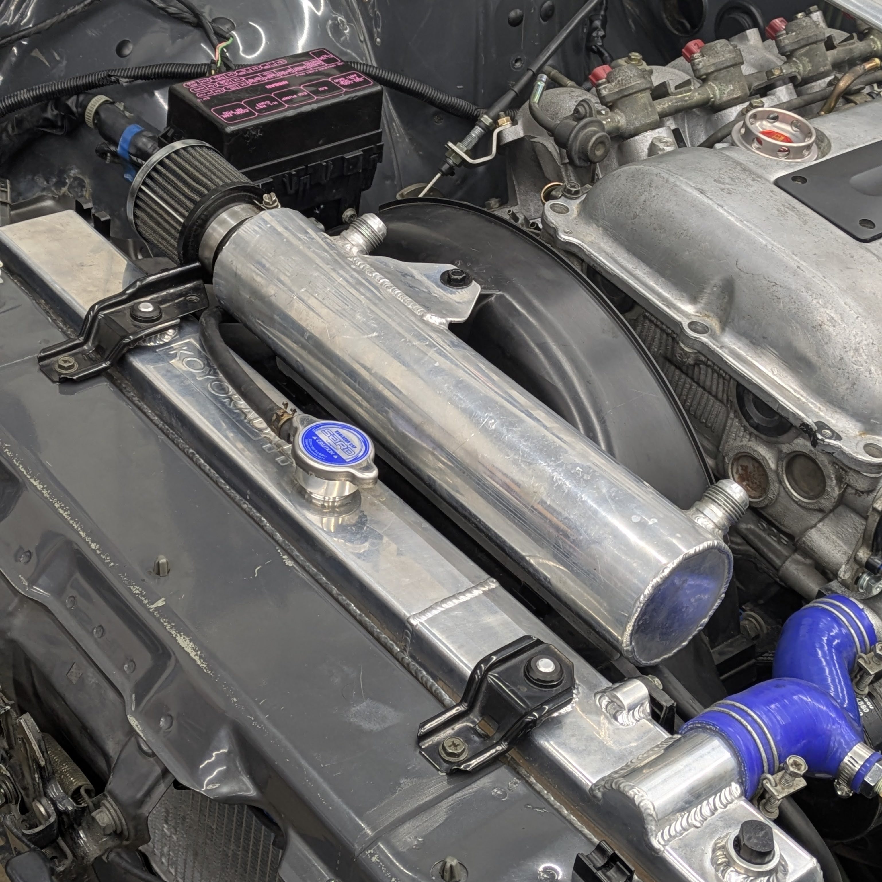
This is a 1 off piece fabricated by David Rybo, a local fabricator to the Seattle area. I found it minutes after it was posted as part of a driveline partout not even 15 minutes from my house. It was originally intended to plumb into the T fitting and PCV check valve locations with Radium press-in AN fittings eventually venting to atmosphere, but it didn’t sit right with me. I didn’t love the visual modernity of the Joe’s Racing filter, and my car doesn’t make enough power, nor breathe enough, to justify the external venting. After deciding to recirculate it back into the intake, I looked at the internal plumbing to determine if it was possible. Both AN ports are plumbed straight into a small chamber full of copper scrubble, with a perforated plate separating it from a shared center chamber. In my recirculated configuration, it will go into one of those air separation chambers, through the empty center, and into another separation chambers before exiting into the inlet barb on the Greddy Suction Intake pipe. This should mean effectively no oil can make it back into the intake, but if it does, it’ll be greatly reduced and the turbo can have a little oil as a treat.
(Thomas from the future: catch can hits the hood. Fuck. New catch can solution coming soon)
With the cooling system almost complete, I wanted to finish out the rest of the plumbing to establish routing of other systems.
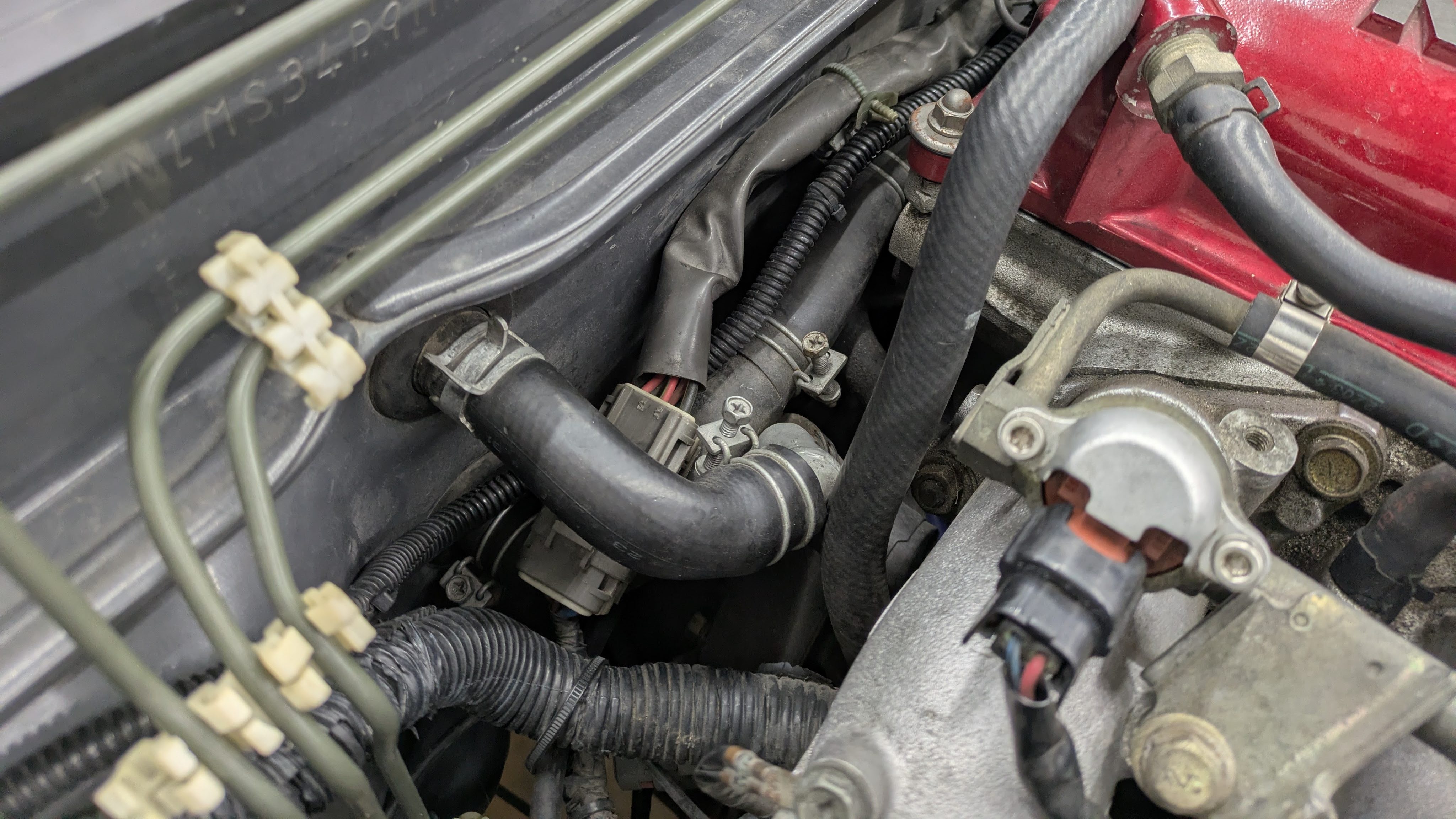
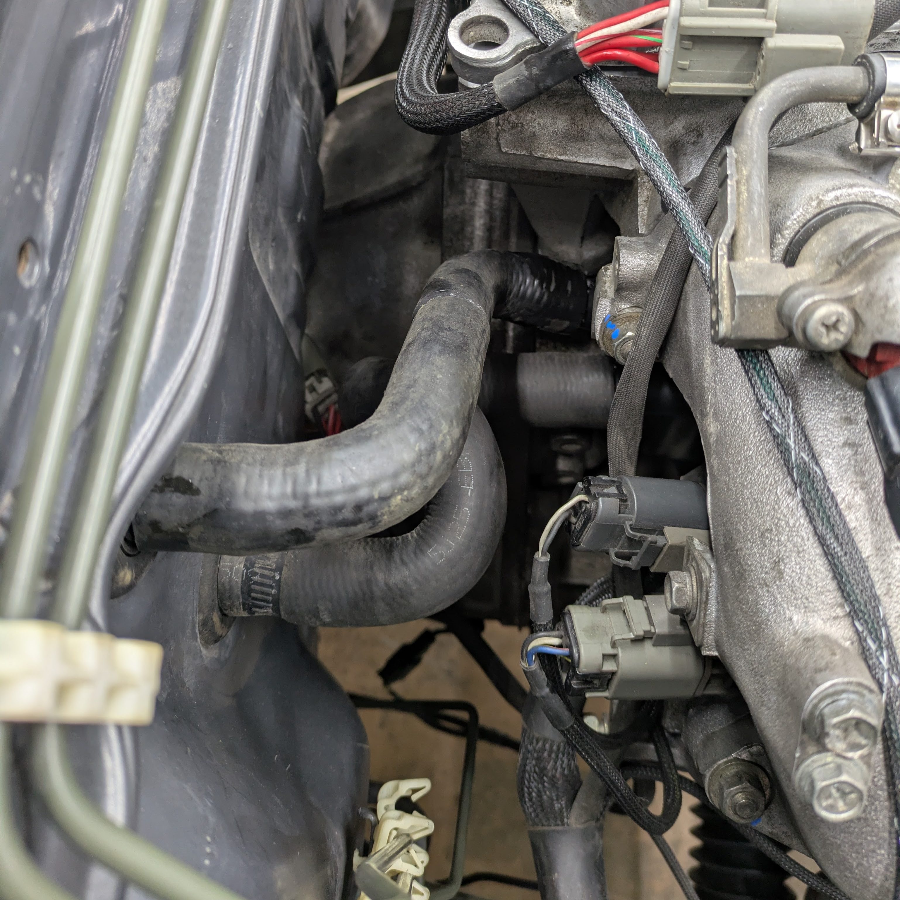
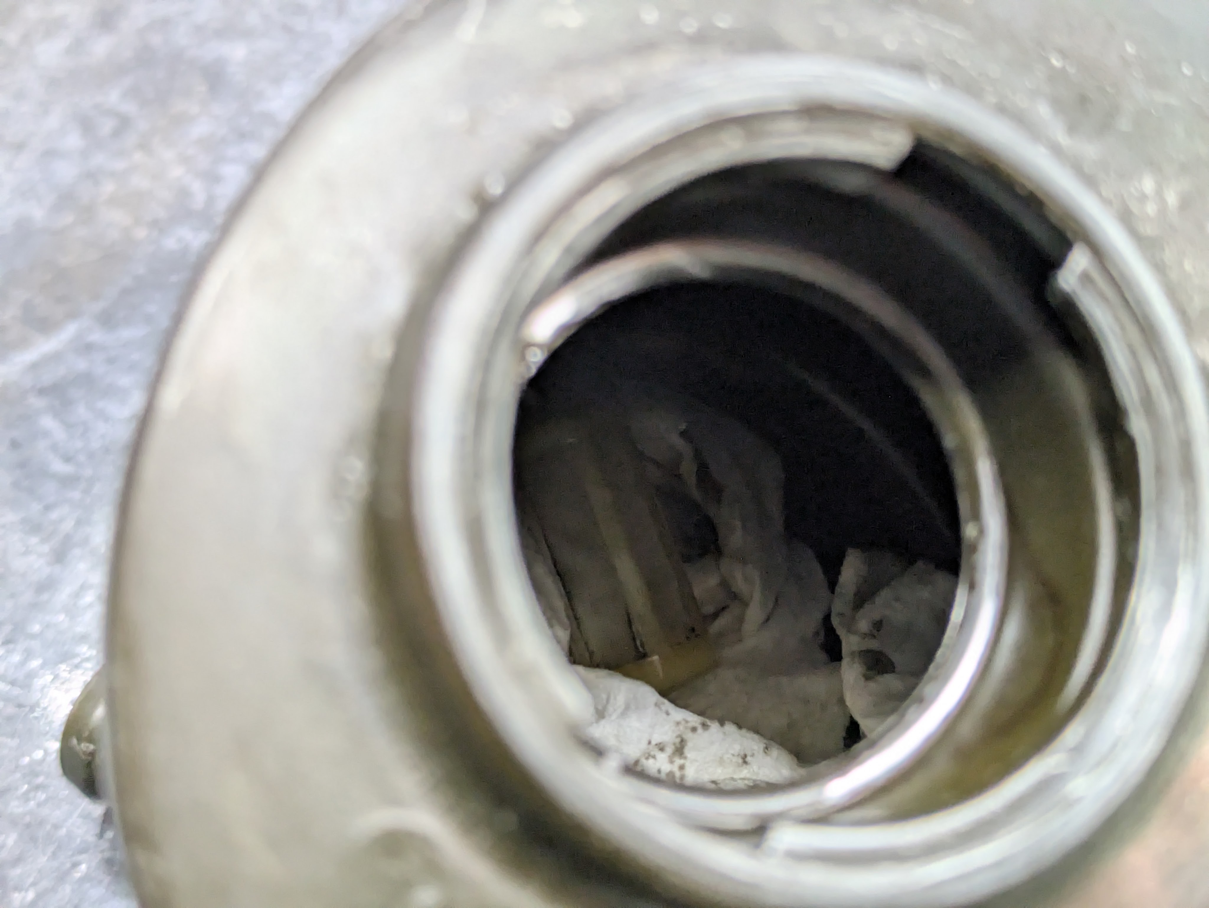
Anyone who has dealt with LHD SR20 swaps knows the dreaded heater core problem. The factory routing is terrible for LHD as the hardpipes are configured for RHD, and even simplified systems with parts store hoses leave a lot to be desired. I am not one of those people that can just tighten a clamp harder to pinch a hose down to fill an 1/8″ discrepancy in diameter and go “OK send it”.
You can see in the above image how most of them end up looking, which is a pile of heater hoses behind the intake manifold, which makes any kind of service rather hellacious. Additionally, 3 of the 4 connections are 5/8″ (yes it’s actually metric but fuck off), but one just had to be 3/4″ for some God forsaken reason. Combined with the packaging constraints and the rather short run, this ends up becoming quite annoying for someone with the tendencies I posses.
This was my first attempt at simplified routing. I had purchased the Faction! heater hose kit and found it to be rather unsatisfactory. They do say you have to cut it up, but its just two Gates hoses with the part number stickers ripped off and no directions. I cut up one of their hoses, threw in a metal soft hose union, and reused one of the hoses that came with Luis’s engine, which is the right size for the engine outlet, but too large for the heater core, thus the requirement of smashing it with a clamp.
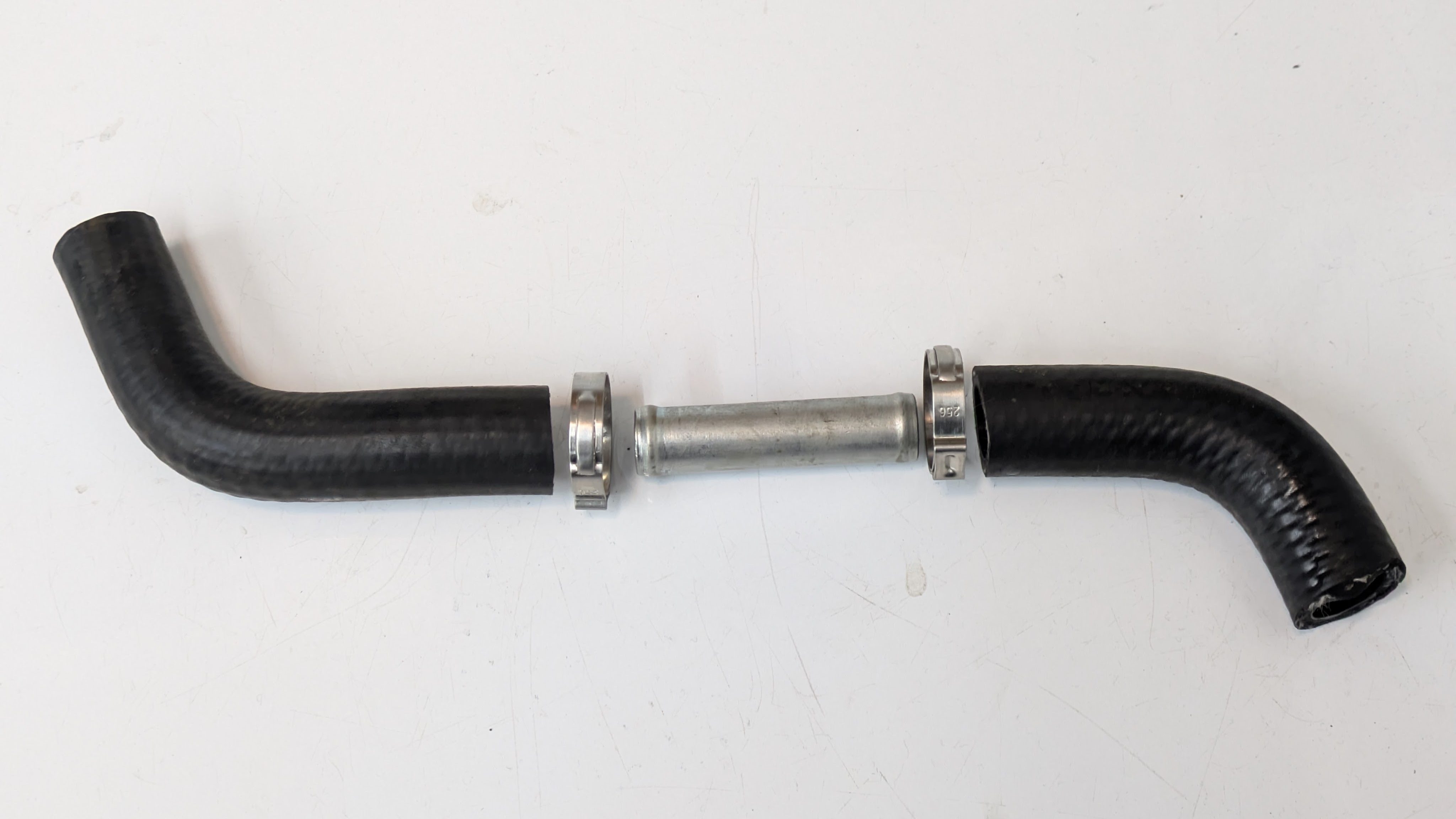
I was very unsatisfied with this solution as it didn’t accomplish serviceability nor restoration to new parts as I was forced to reuse some. It also just didn’t look nice, and I do believe that things can look nice and perform well with some effort, you just have to know what to put together.
And then one day, I was introduced to magic (a new section of Pegasus Auto Racing Supplies’ website)
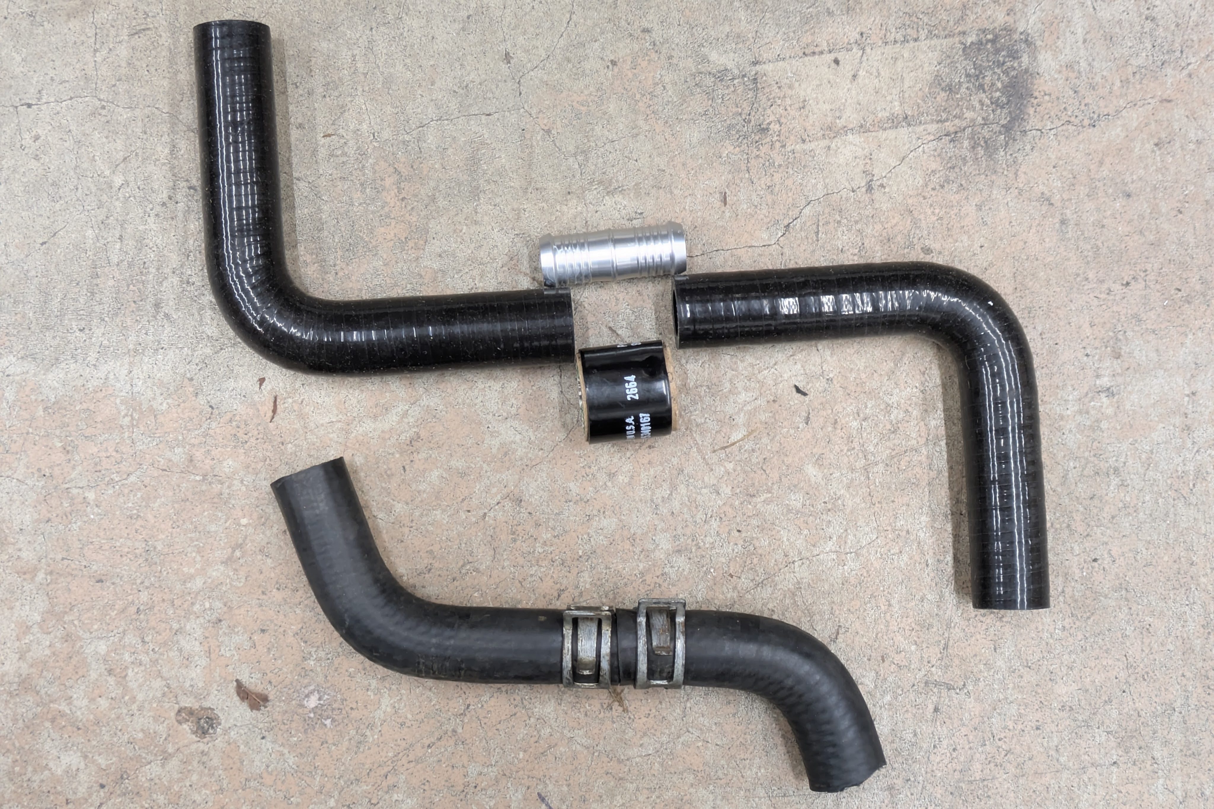
Pegasus has put together an all-in-one solution for custom hoses so you don’t have to piece it together from multiple sites. My father told me about it as he had been working on a project that also made good use of them. While none of these products are new or transformative, the fact that they are all race grade and centralized is a big deal for me.
The hoses are pretty standard molded coolant-rated silicone, which does have the downside of being water-permeable (PSA: if you have silicone hoses, check your coolant level once a year, because water can evaporate through it). As this car has other silicone hoses, and it’s a track car that gets a yearly coolant switchover, I’m not sweating it much. The hose unions are nothing special. Just the right amount of barb and diameter for silicone applications.
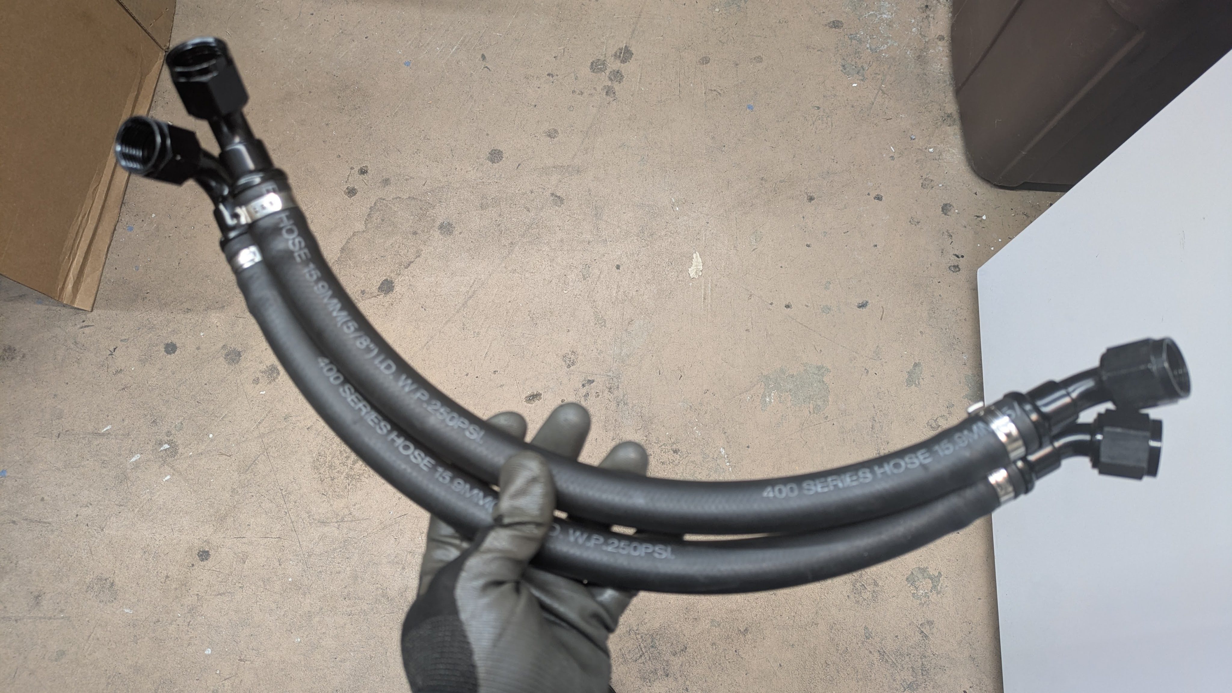
The really cool part is the Gates Powergrip heat shrinking hose joiners to seal up the unions. You can think of it like a permanent and constant tensioning clamp as it thermally cycles. This technology is 15+ years old and used more in heavy industrial applications, but has had a slow trickle to grassroots automotive. You slide it over the hose joint and shrink it like a piece of heat shrink, and once it’s on there, its not going anywhere. This setup, combined with smooth lined worm gear clamps that they also sell, allowed me to make exactly the shapes I wanted with tight radiuses, and make the routing as direct and serviceable as possible.
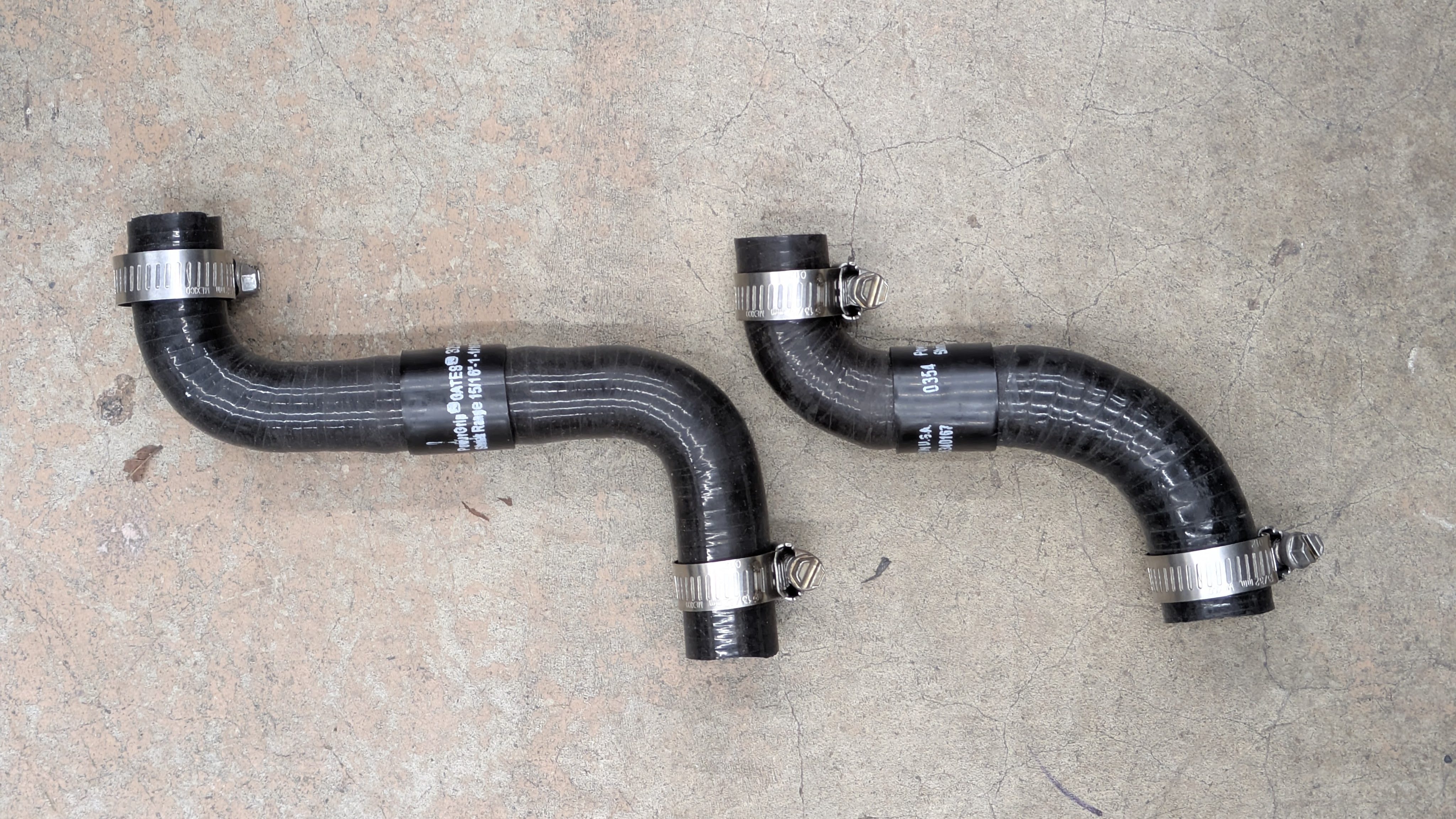
These are the finished results for both runs. The other magical part that this setup allows is they have diameter transitioning bends. You can see that the hose section on the far right side is the 3/4″ diameter required for the special barb, while everything else is 5/8″. While this could be accomplished with a barb set up for a diameter transition, this is just so clean.
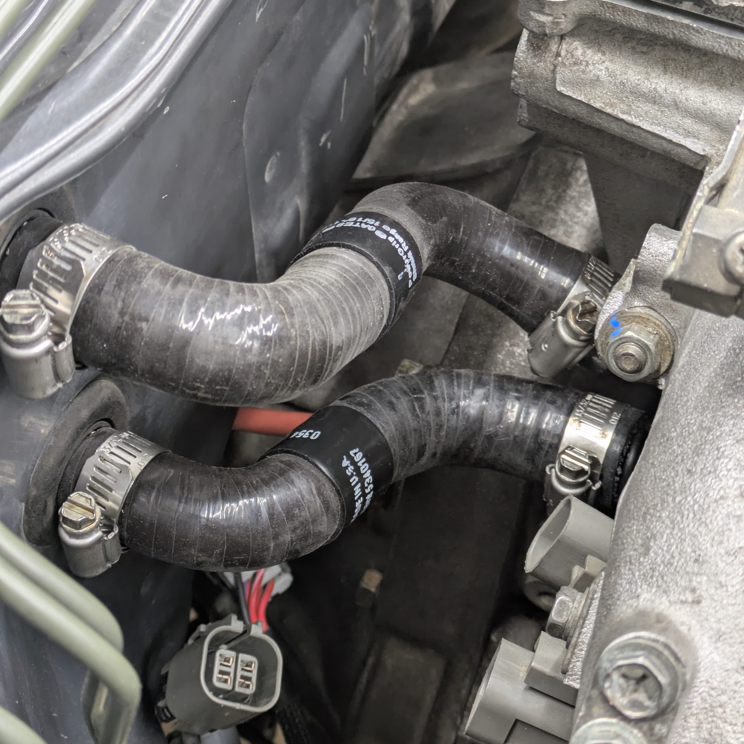
With them installed, I am thrilled with the results. It is simple, clean, diagnosable, and easily repeatable should I have to make another one. If you have a hose cutter, all this stuff is really easy and pleasant to work with and it took hardly any time to make really pro hoses.
The one downside, of course, is cost. What you are looking at in the image above cost about $100 dollars in 2026 to make. While absurd on their own. I’d pay $100 dollars to (hopefully) never deal with a coolant leak, and the other options on the market range from $40-$60. I say money well spent, but I am certainly not the median.
With the cooling system sealed up, it was time to proceed to the other cooling system (unfortunately not AC)
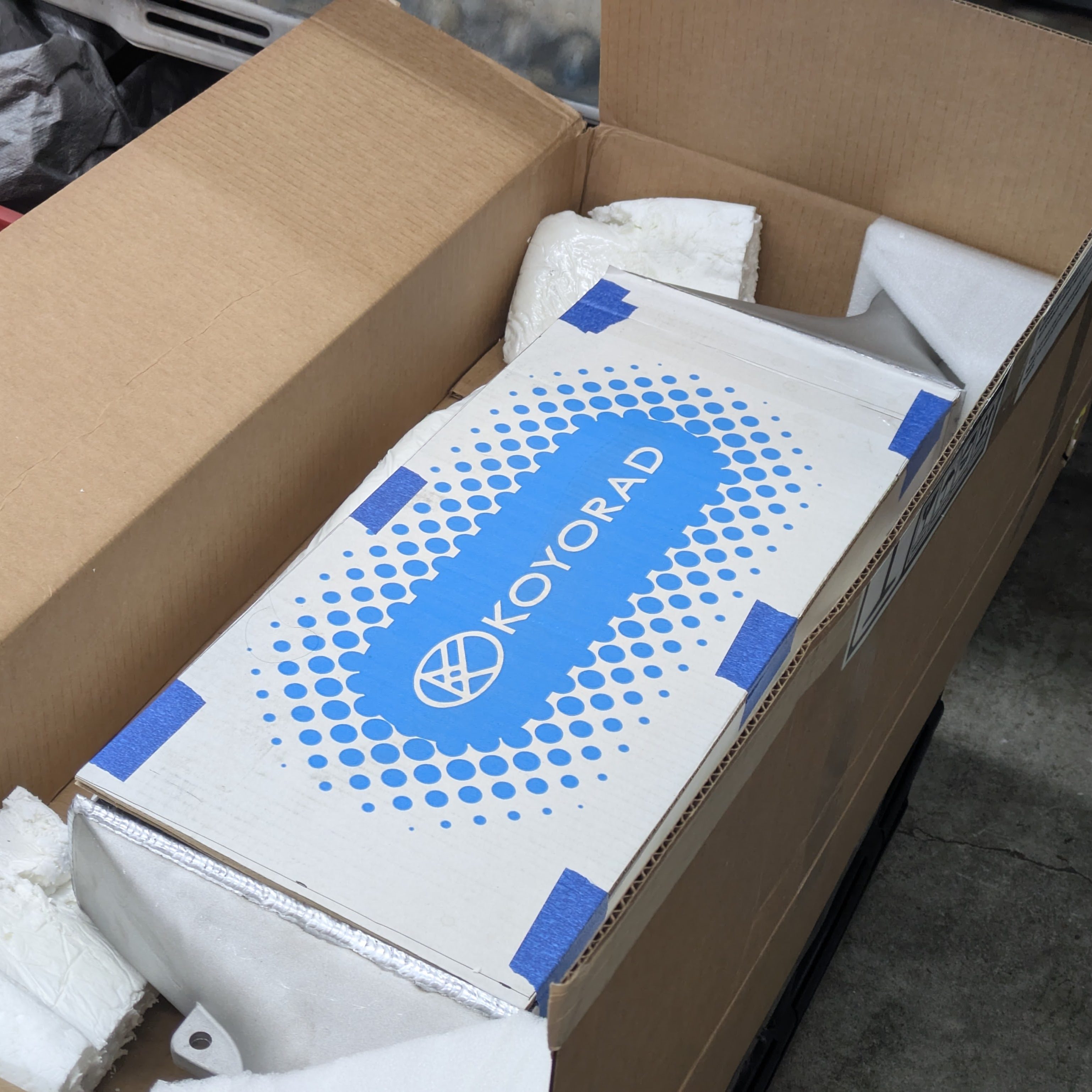
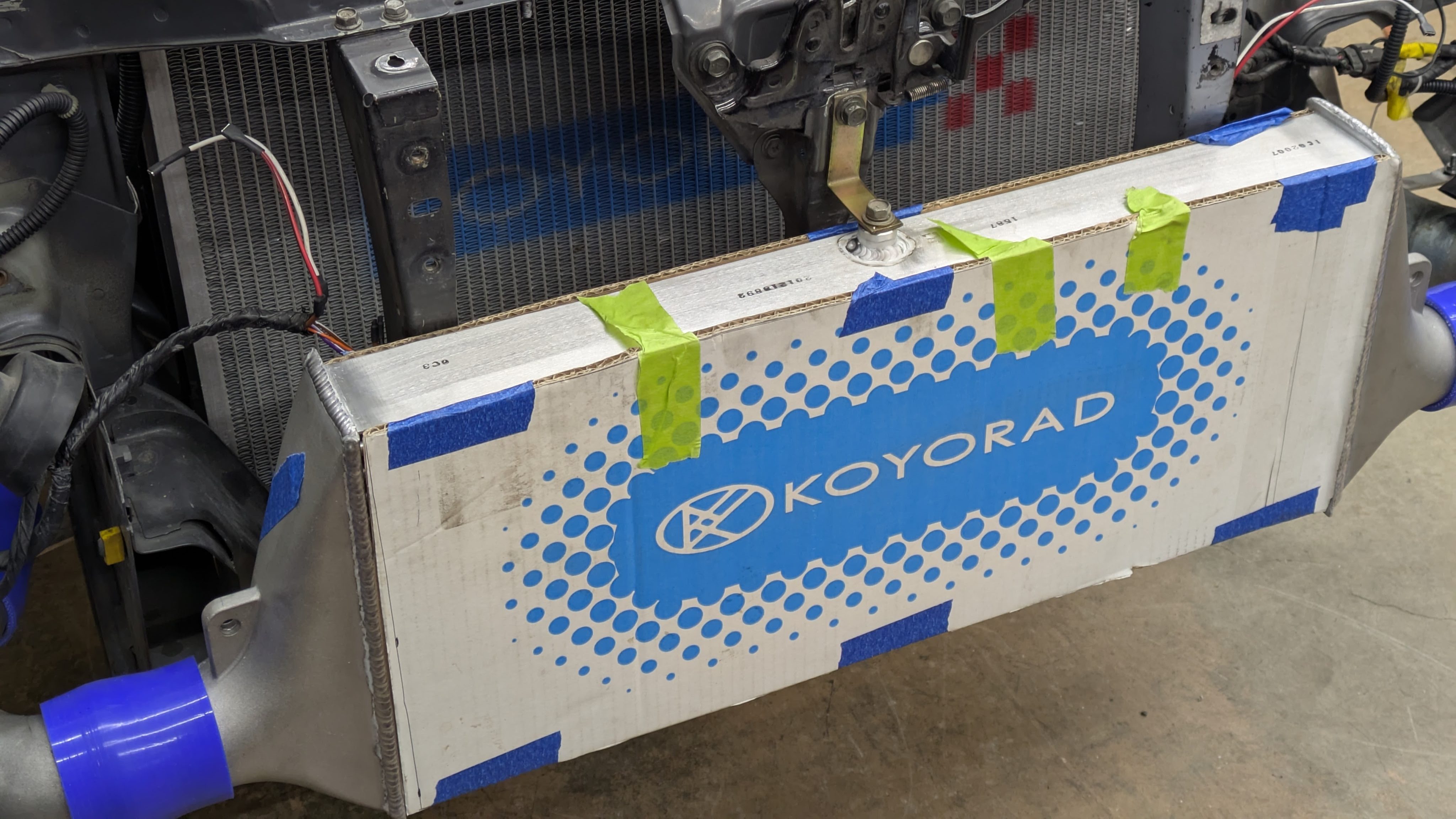
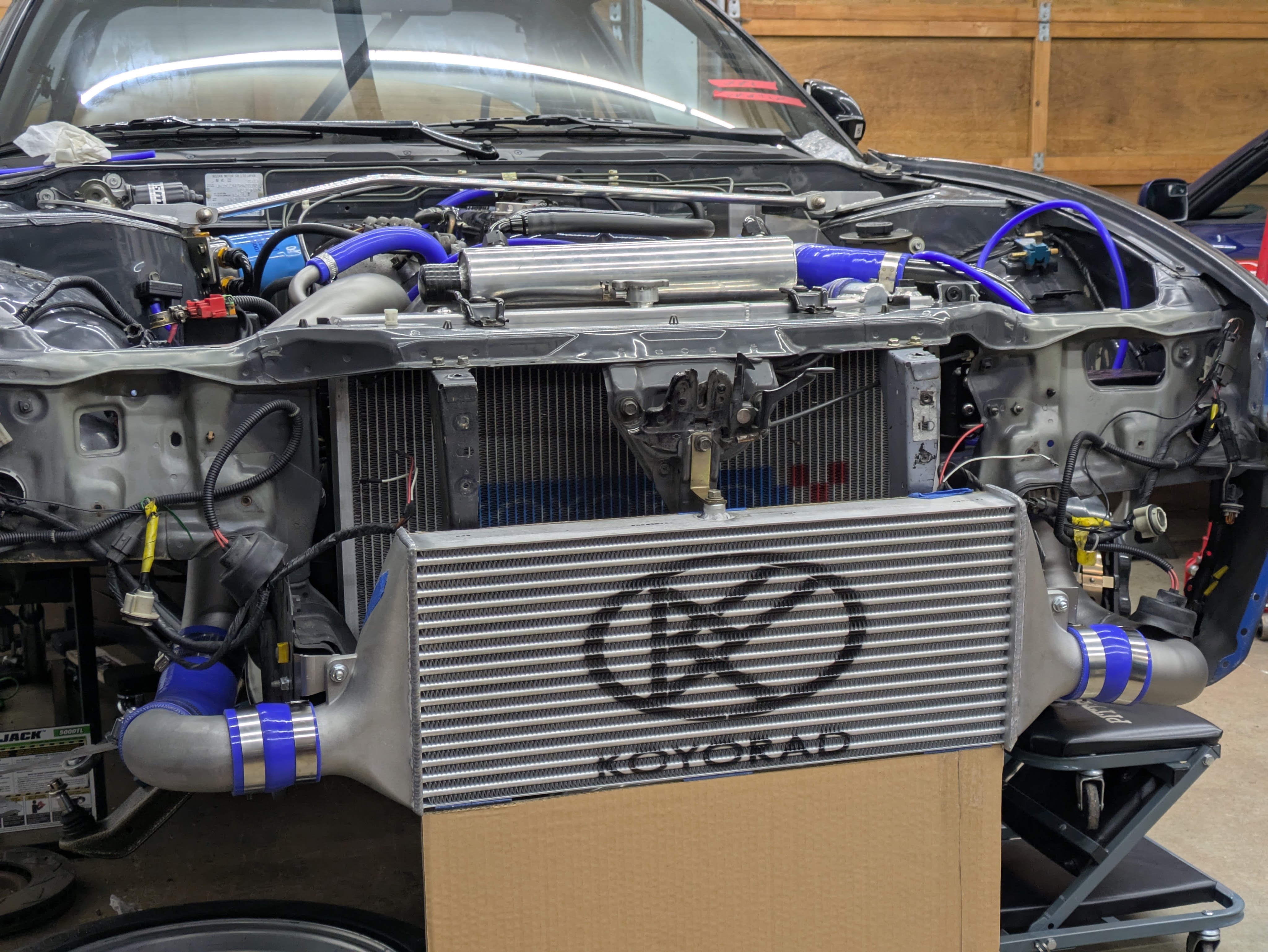
I came home one day to a weird flat-ish box, which evidently was my intercooler that I had ordered on Black Friday. Let’s just say my old one had seen better days.
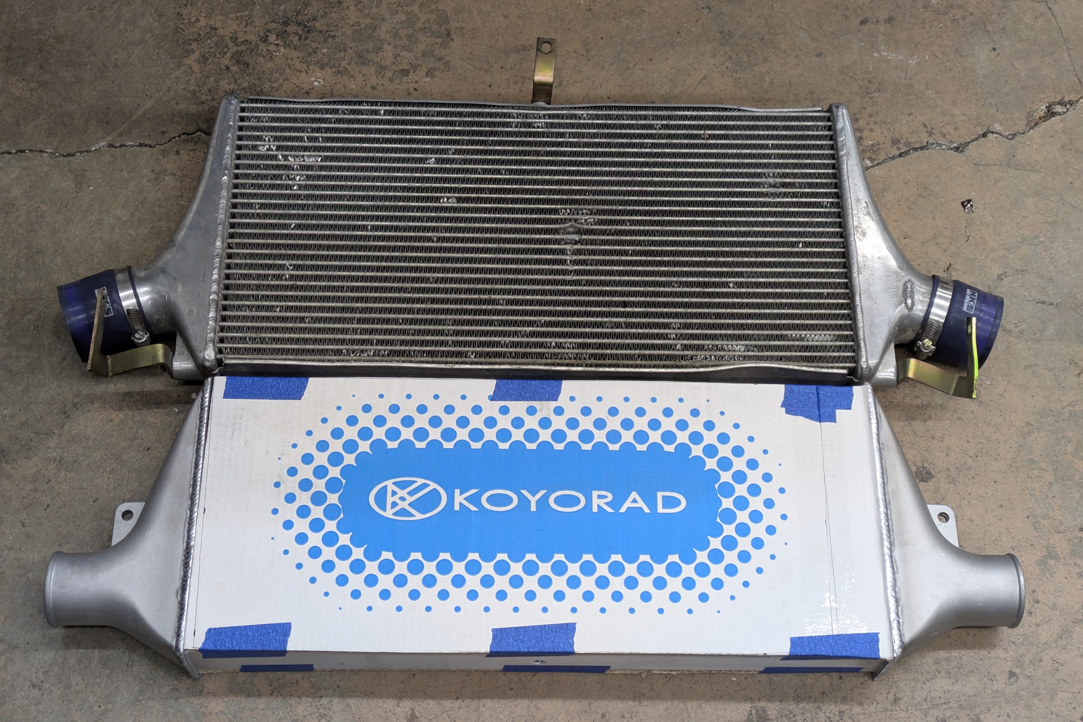
This Koyorad intercooler came way of Touge Fatory. This is the cast tank option for their bar and plate Koyo intercoolers. I chose this particular core size as it pretty much perfectly matched the dimensions of my old one, had good side mounting provisions, and didn’t have to be purchased as part of a whole kit with piping. I wanted to retain my old intercooler piping if possible, for both cost and period correctness, so this was a great option.
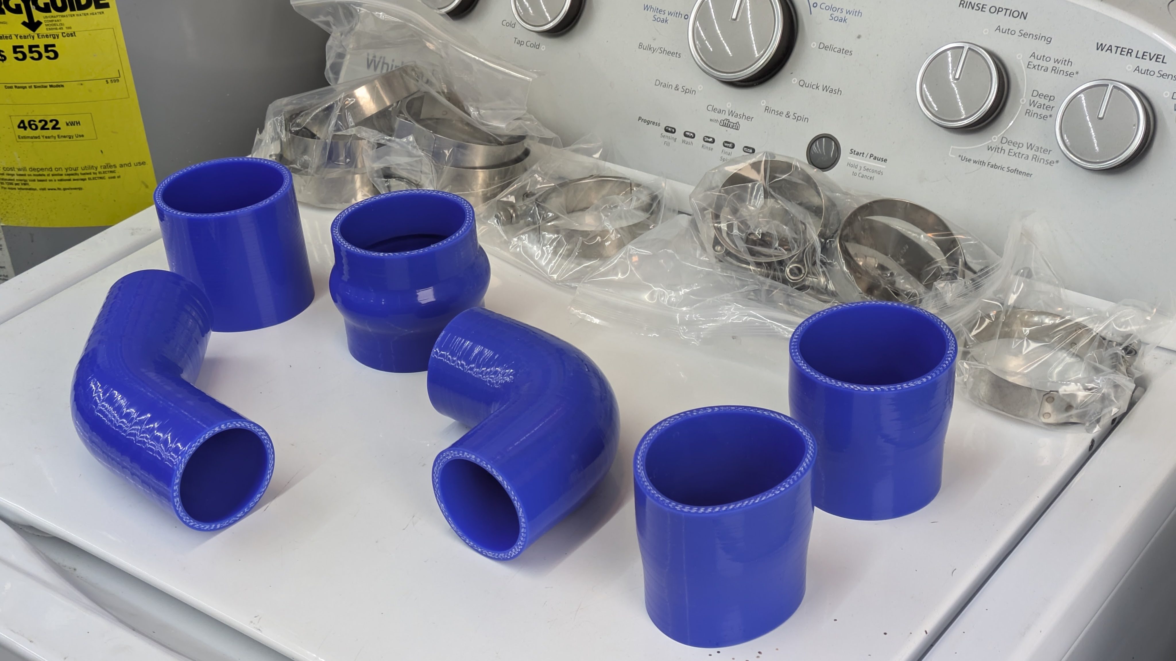
Once the intercooler had arrived, I sized up and ordered all the couplers and clamps required to stitch the whole system together. While the old HKS couplers were in shockingly decent shape for their age, a few of them were showing it, and the factory SR20 couplers found on the turbo outlet and BOV pipe were showing it more. Same goes with the clamps, they are so cheap I’d rather just have all new T bolts to start fresh with.
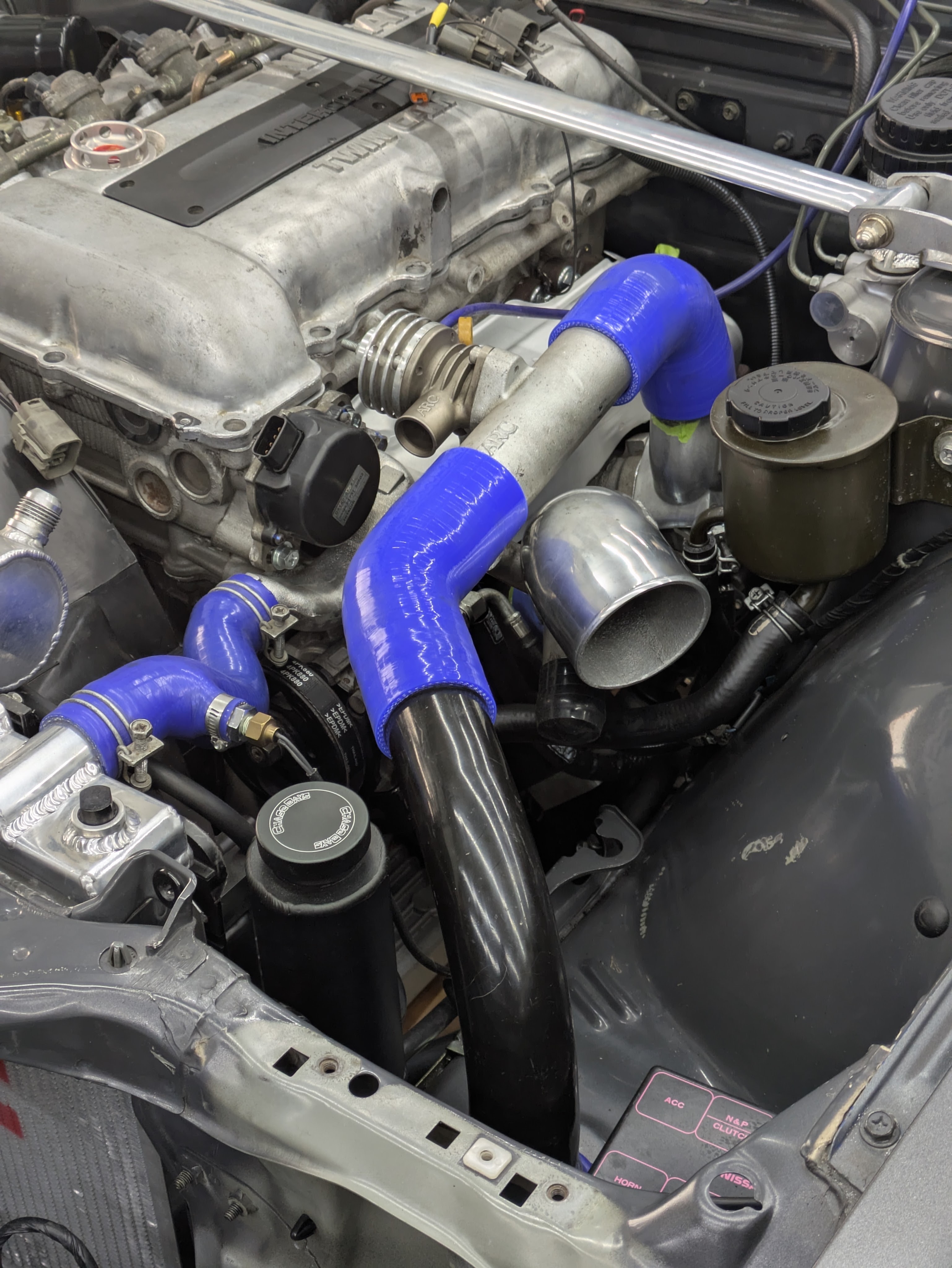
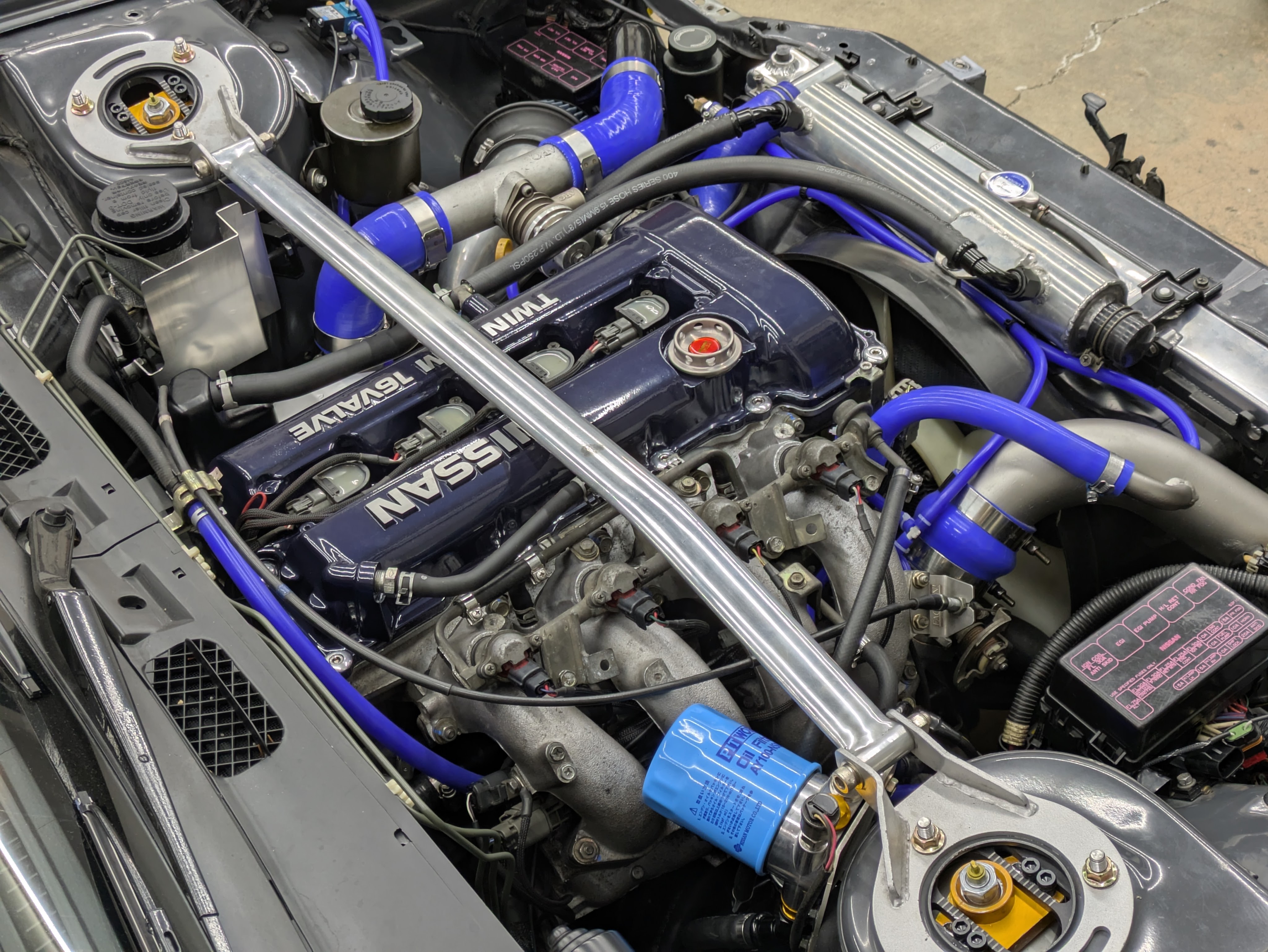
The blue was a very intentional choice, and this was the first time I have ever made a conscious effort to style a bay outside of cleaning things and routing things nicely. It was entirely driven by the fact that the upper radiator hose is blue, and that wasn’t going to change because of the Defi sensor conveniently located in it. I figured if I was going for early 2000s D1 Street Legal era, blue was the way to go.
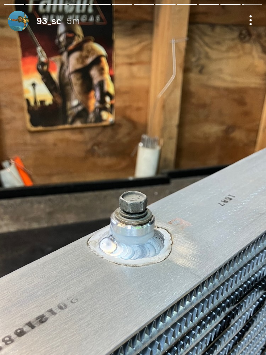
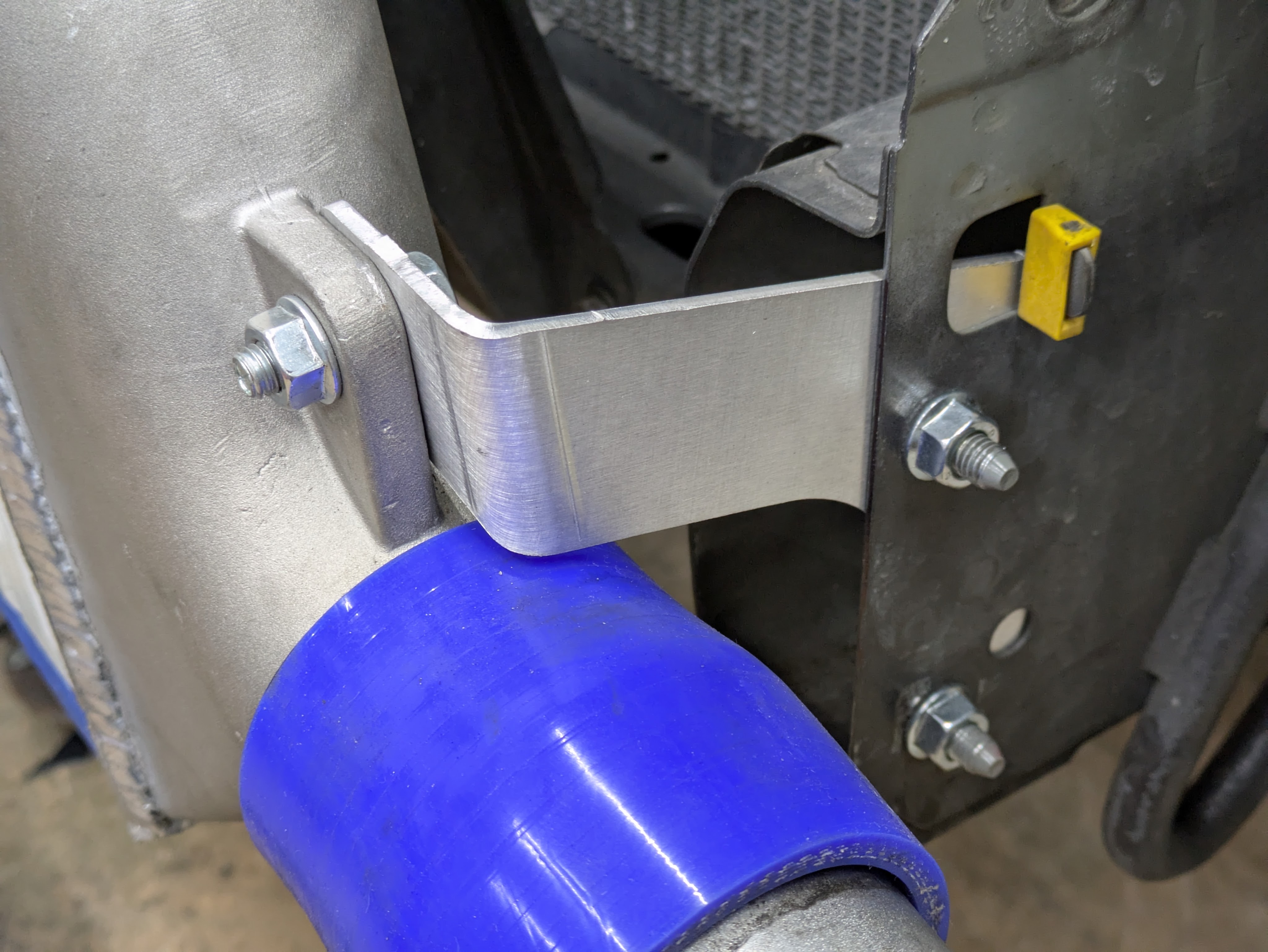
I wanted to reuse as many of the old mounting brackets from the HKS intercooler that previously adorned the car as I could, so I figured a center mount and two side mounts were the way to go. The intercooler had no top mounting provision out of the box, so I turned a threaded boss out of some 6061 I had in my toolbox and had melted magic wizard Ethan buzz it on in the exact same Y position as the old intercooler. The fitment was perfect and the finish was great.
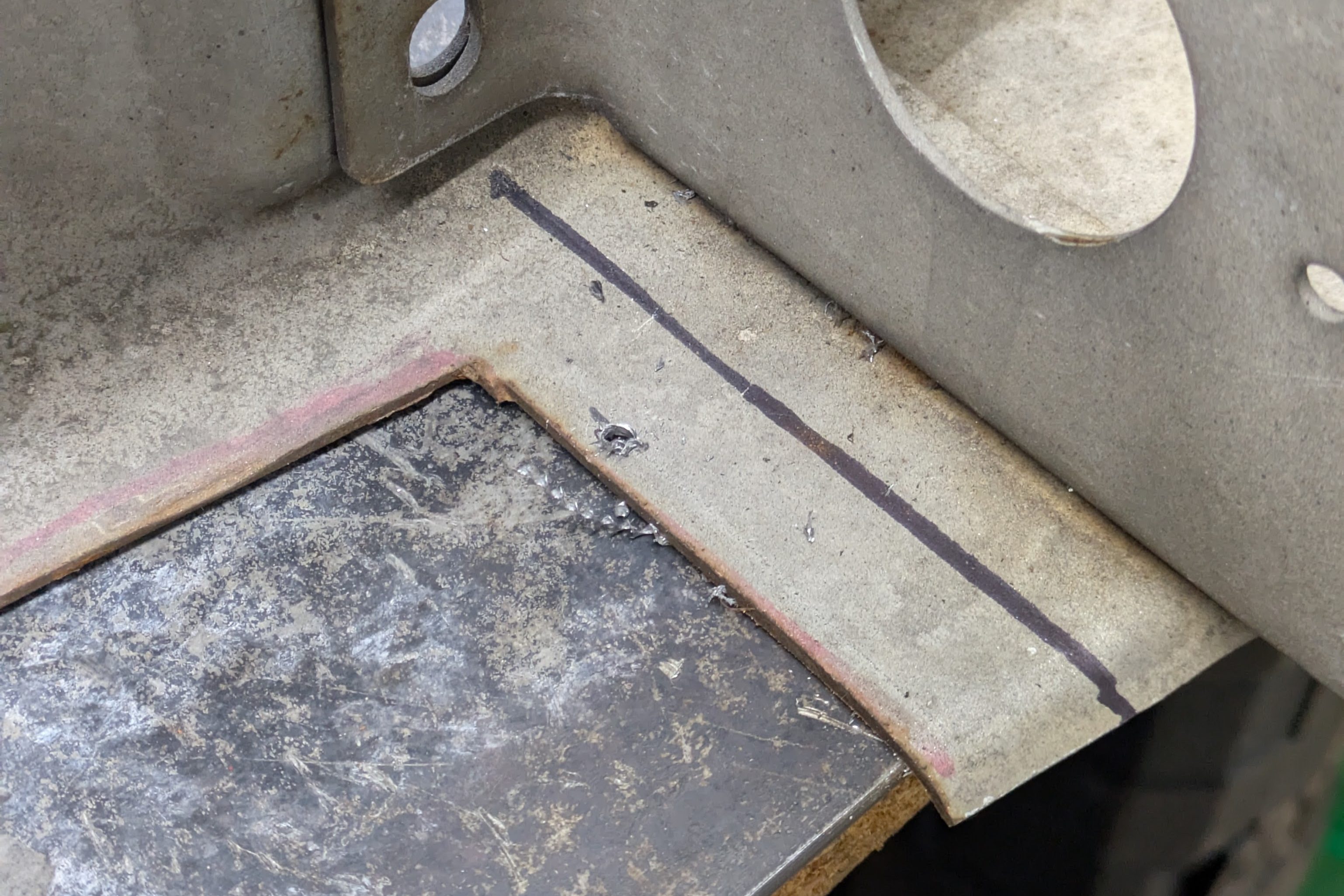
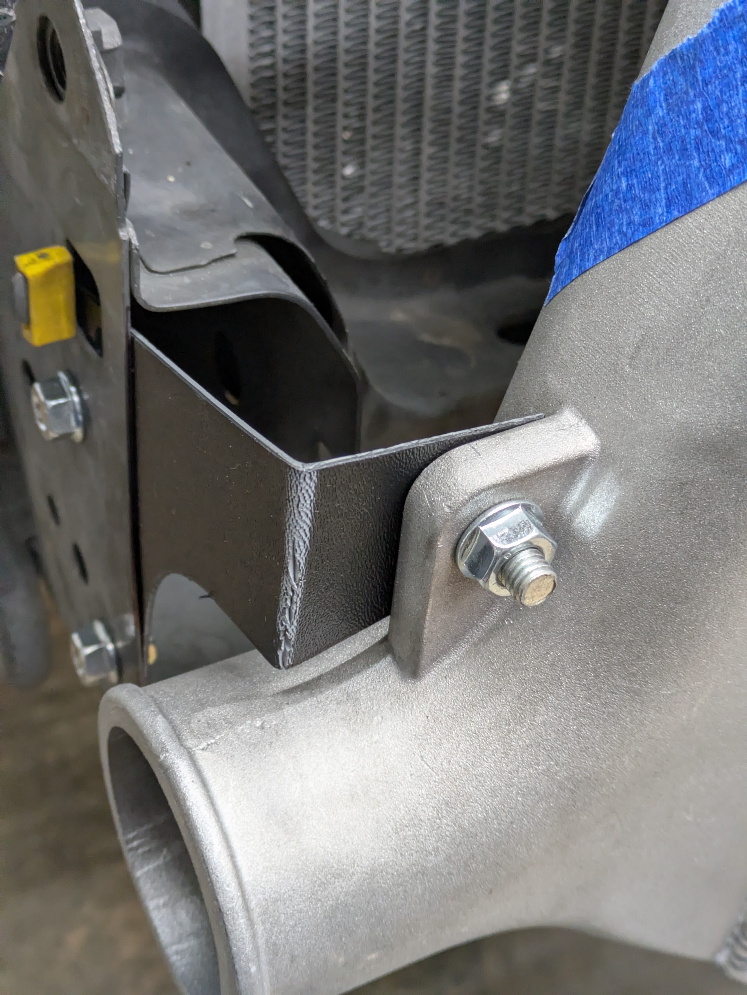
For the side mounts, it was going to be a lot trickier. The old intercooler had mounts that screw in to the sides of the end tank, where this one has a fore/aft facing hole. I spent some time debating what it was going to take to hang the intercooler with what I had, and while achievable with the old brackets, I wasn’t stoked with the idea of the intercooler hanging from the crash bar; Id rather be able to remove the front end without cracking the charged air system. This left attaching it to the end of the frame horns the best option. Since these mounts needed to be pretty organic since they were now 6 dimensional, my father came up with the idea to use thin ABS sheet to effectively CAD our way to a usable bracket. While I messed around with another project, he spent the time to cut and bend up some non structural, but correct geometry mounts.
I took these brackets to work, and since they were thin folded plastic, I unfolded them and used the copier to make a scan of the mount to trace in CAD. It worked shockingly well, and after two printed plastic revisions, the files were satisfactory, and I threw them in with my next SendCutSend order. We will circle back to those during the install of everything.
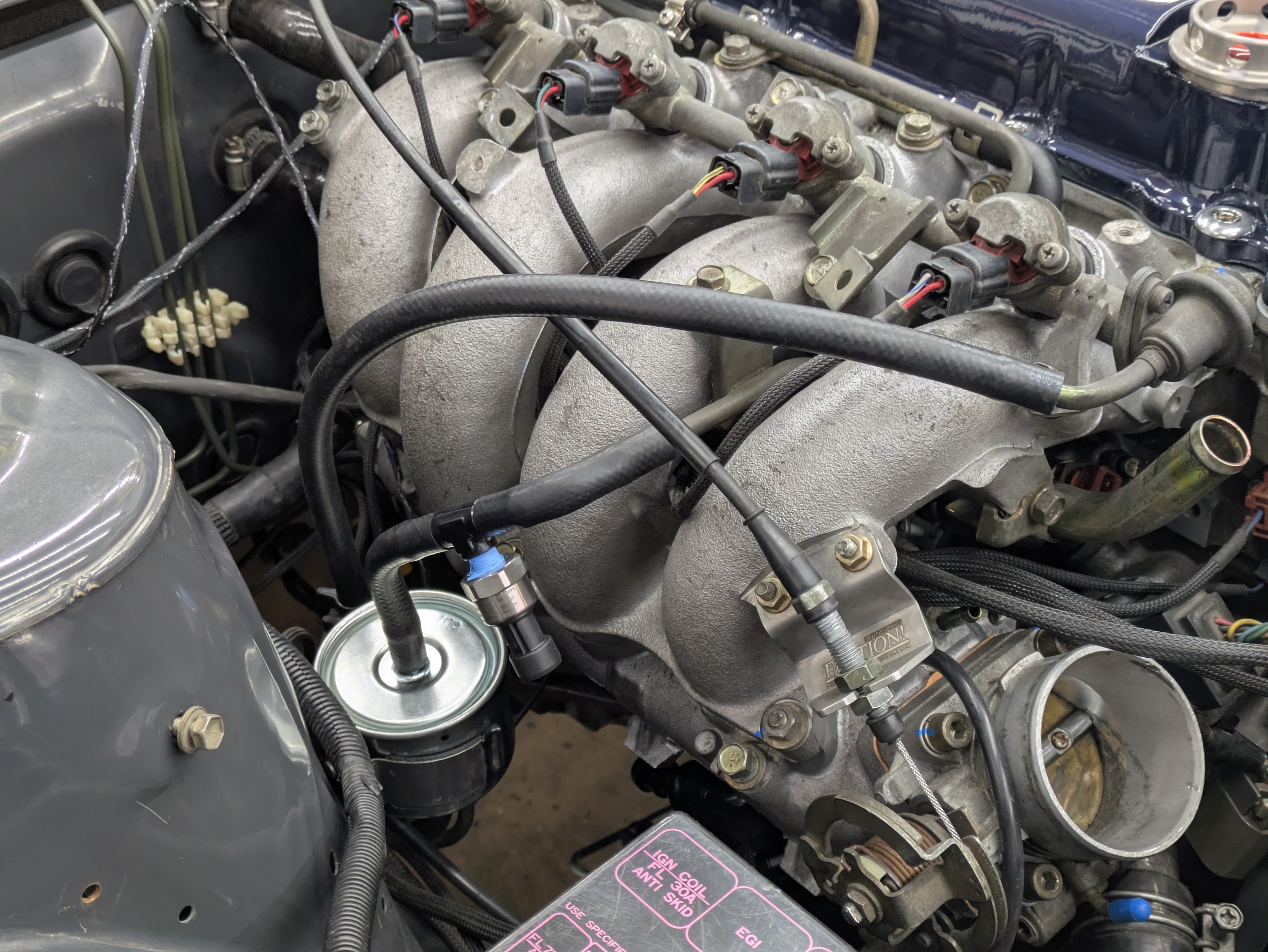
With metal fab on the mind, I spent a far more than a few minutes measuring and mocking up for my oil filter relocation position. I mentioned in the engine refresh post that my one oil change made me resent the filter location, and I added the Mazworx oil block adapter in preparation for the relocation.
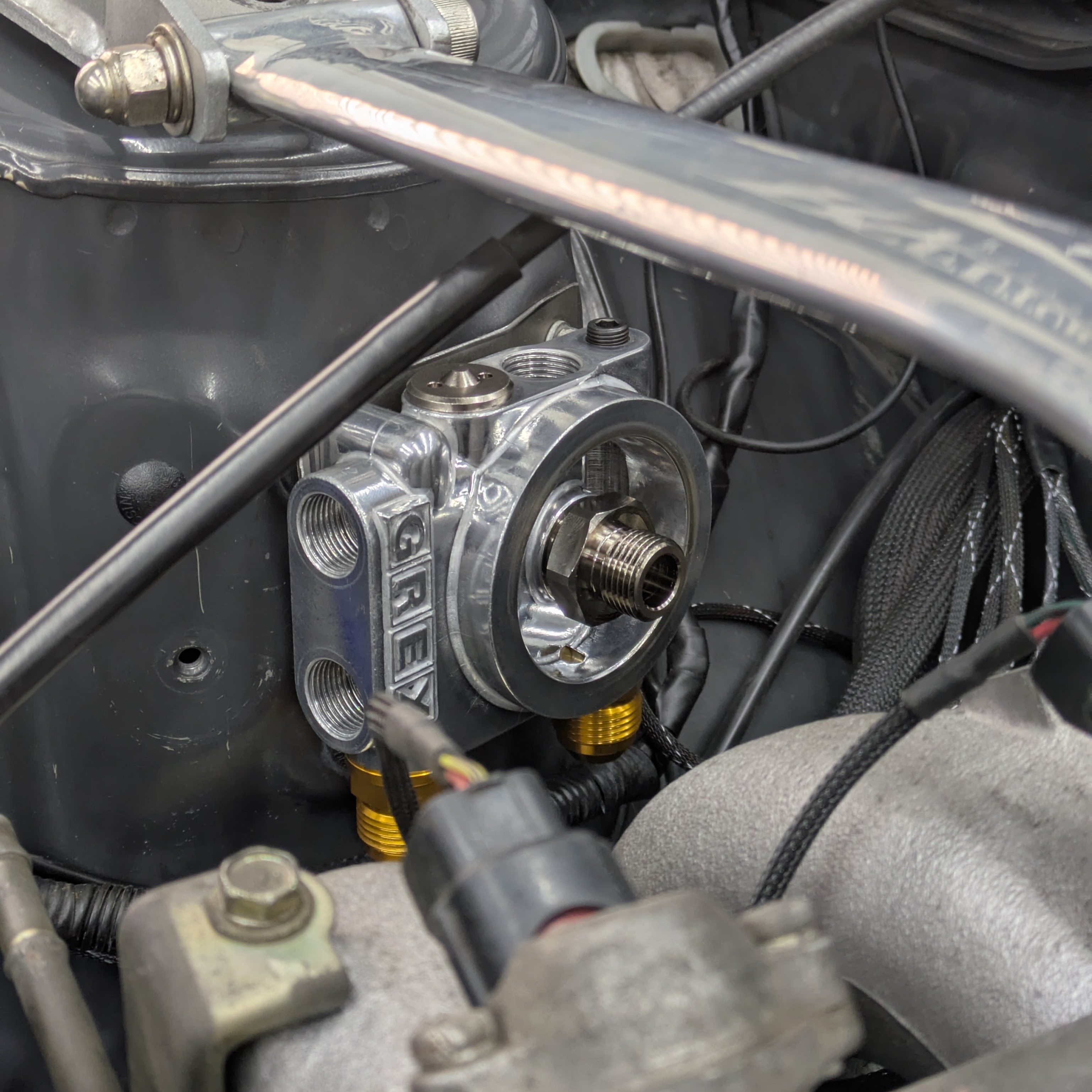
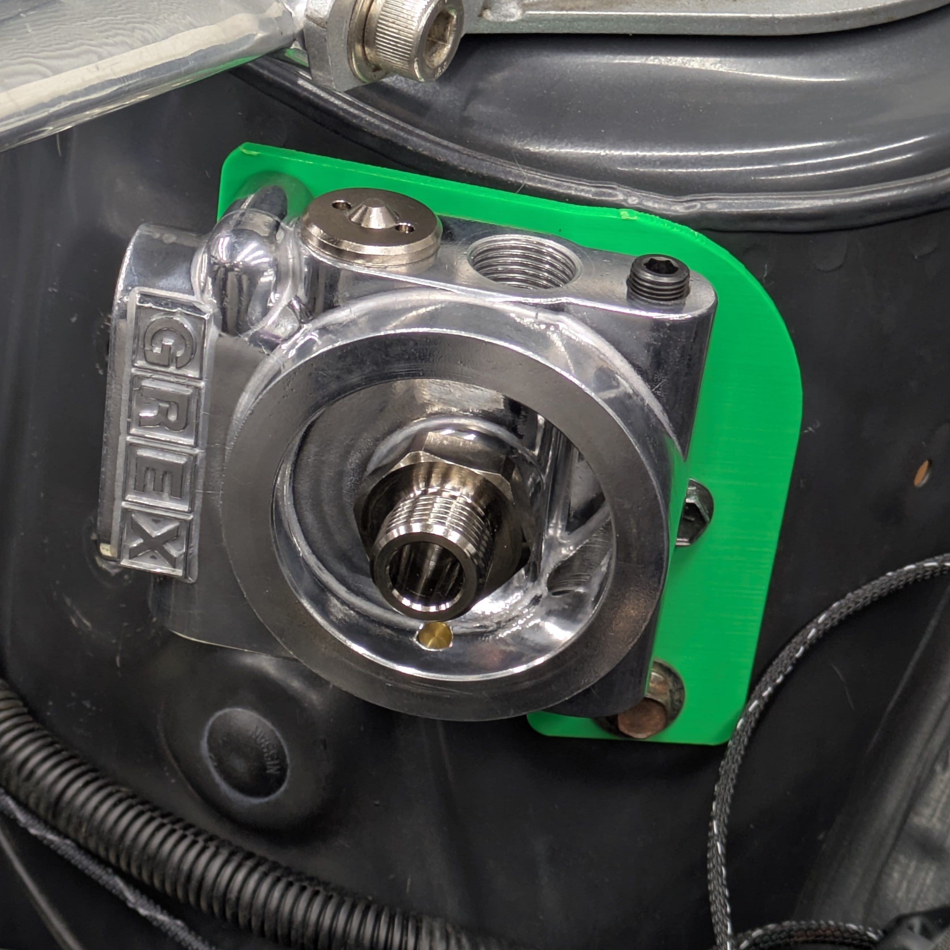
This Greddy oil filter relocation doubles as a thermostat for an oil cooler should I choose to run one in the future. I’ve had similar units from Improved Racing in the past, and while really well made, I wanted something that looked more at home with the current theme of the engine bay, which this unit accomplishes perfectly. It also has an integrated 1/8PT port, which my Defi oil pressure sensor threads directly into.
The outlets near the GREX logo are for the oil cooler. I purchased the loop since I don’t plan to run one yet, but this bracket and system is accommodating for the optimal hose routing should I need one. The other outlets are pointed straight down, which is as good as it’s going to get for this setup. I 3D printed a few versions of the bracket to test fitment, and settled on one that kept the filter and sensor out of the way of everything and the fasteners for the bracket easily accessible.
Once my SCS order was placed, my attention turned to other small projects. My pursuits of simplicity and serviceability led me down a path that I deeply regretted right up until the point that it worked out.
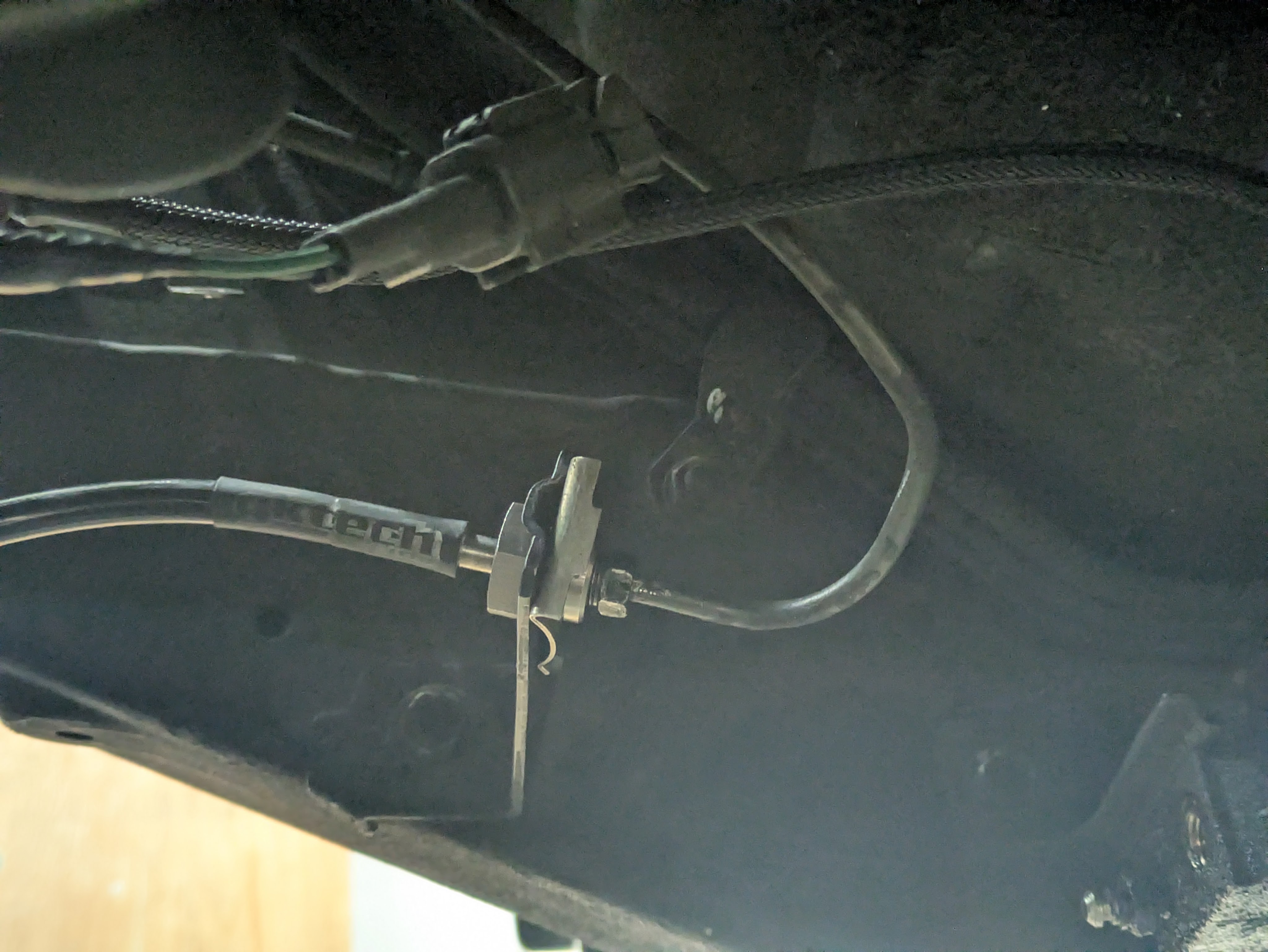
My car, being a factory manual, had the factory metal hard line to the clutch damper circuit, which is effectively a large fluid loop with a diaphragm that smooths out the pedal for casual driving. Since this car no longer sees bumper to bumper traffic on a stock clutch, and the damper can be extremely obnoxious to bleed if opened, I opted to delete it in favor of a short braided hose from our acquaintances at GKTech.
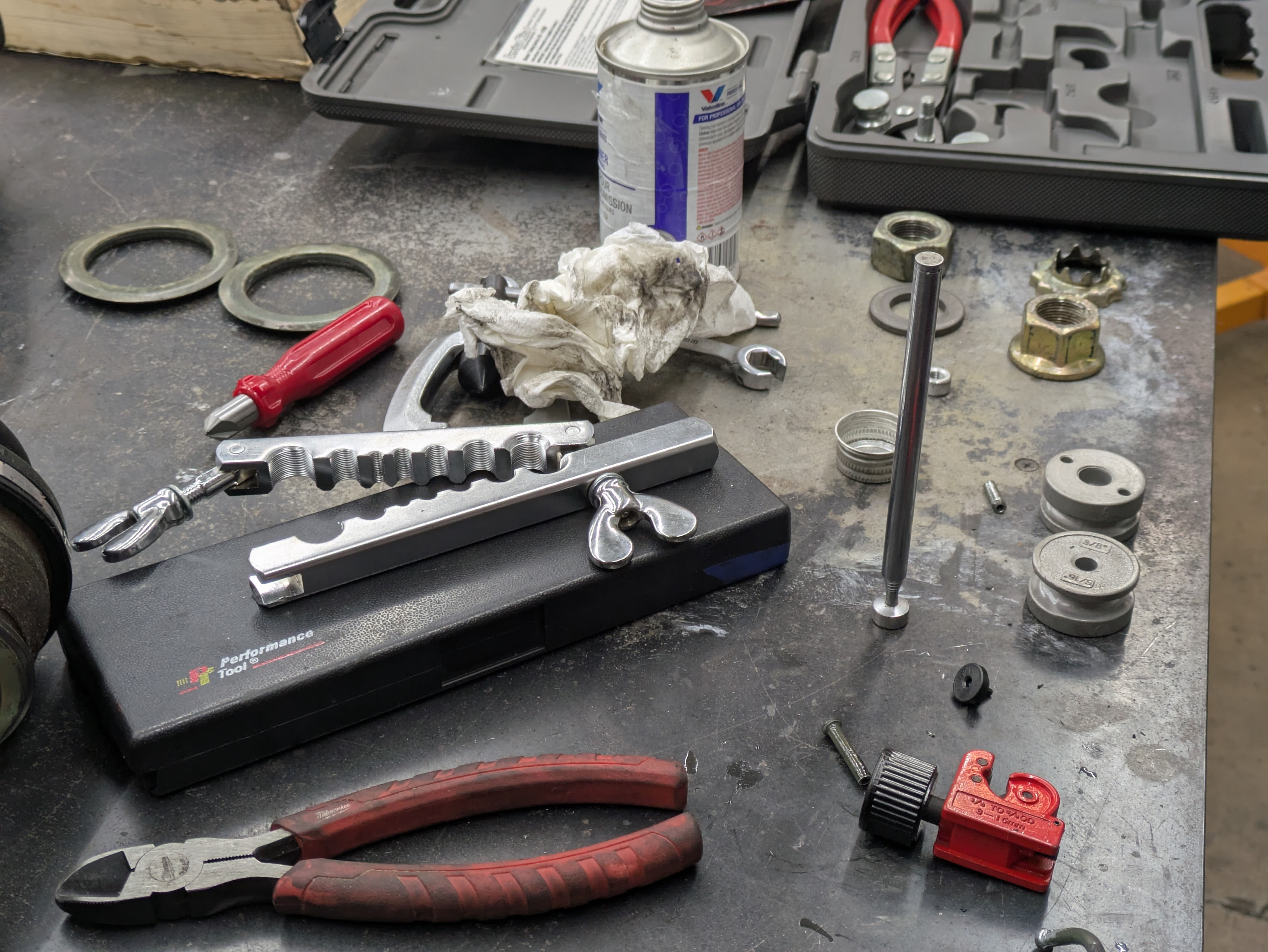
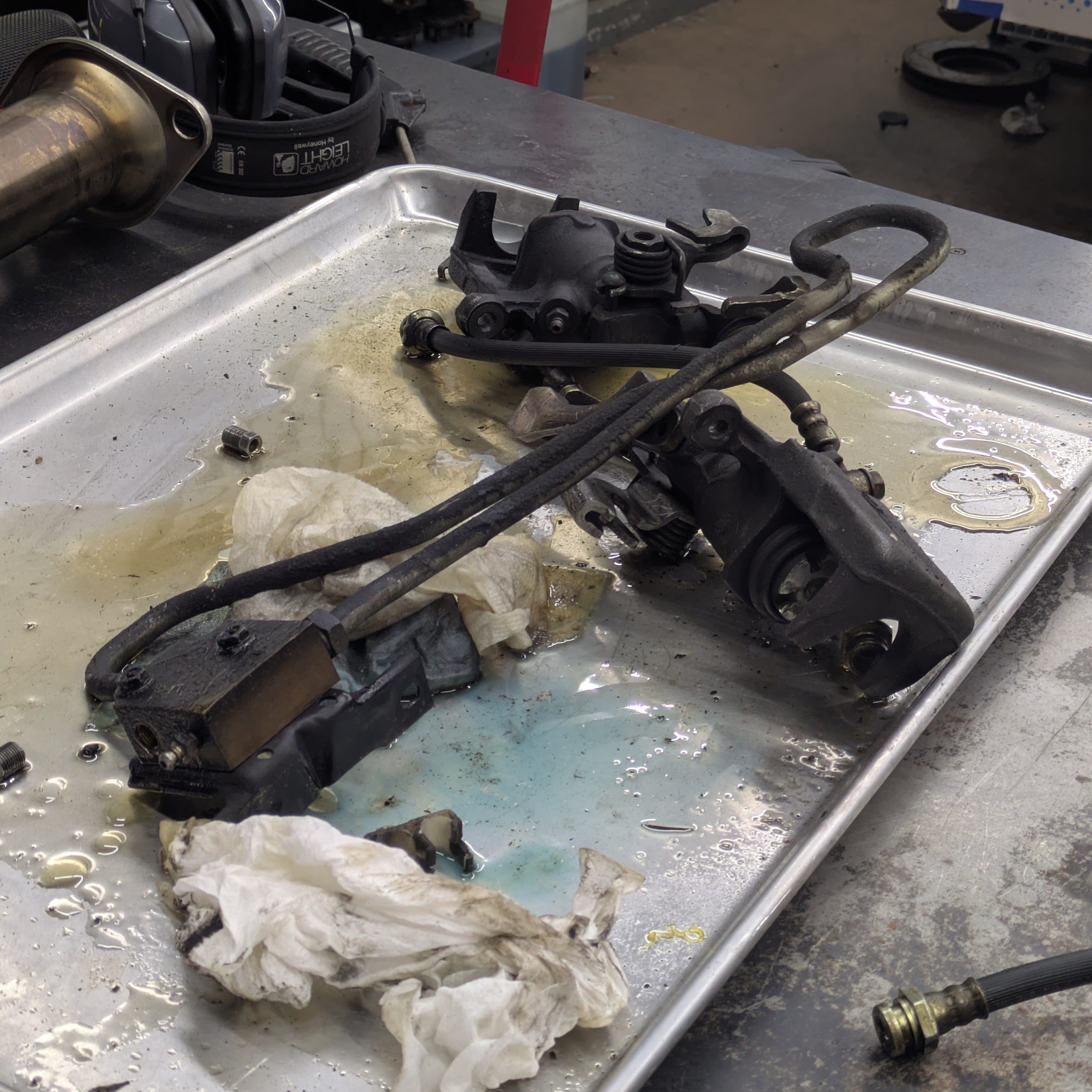
This required the OEM clutch hardline to be re-bent 180 degrees to match up to the hardline bracket on the frame rail. While not too difficult with soft steel tubing, the challenge came when the 1 fitting I needed to be good (the one on the hardline from the master cylinder to the damper) damaged the threads on removal. I tried saving it with an M10x1.0 nut fashioned into a die, but it was beyond straightening. I knew installing a new nut was my only hope of saving the hard line (before giving up and going to a full length soft hose), so I acquired a (cheap) brake line flare kit off of Marketplace, removed the entire master cylinder and clutch line, and spent the time to slip on a new nut and flare the line.
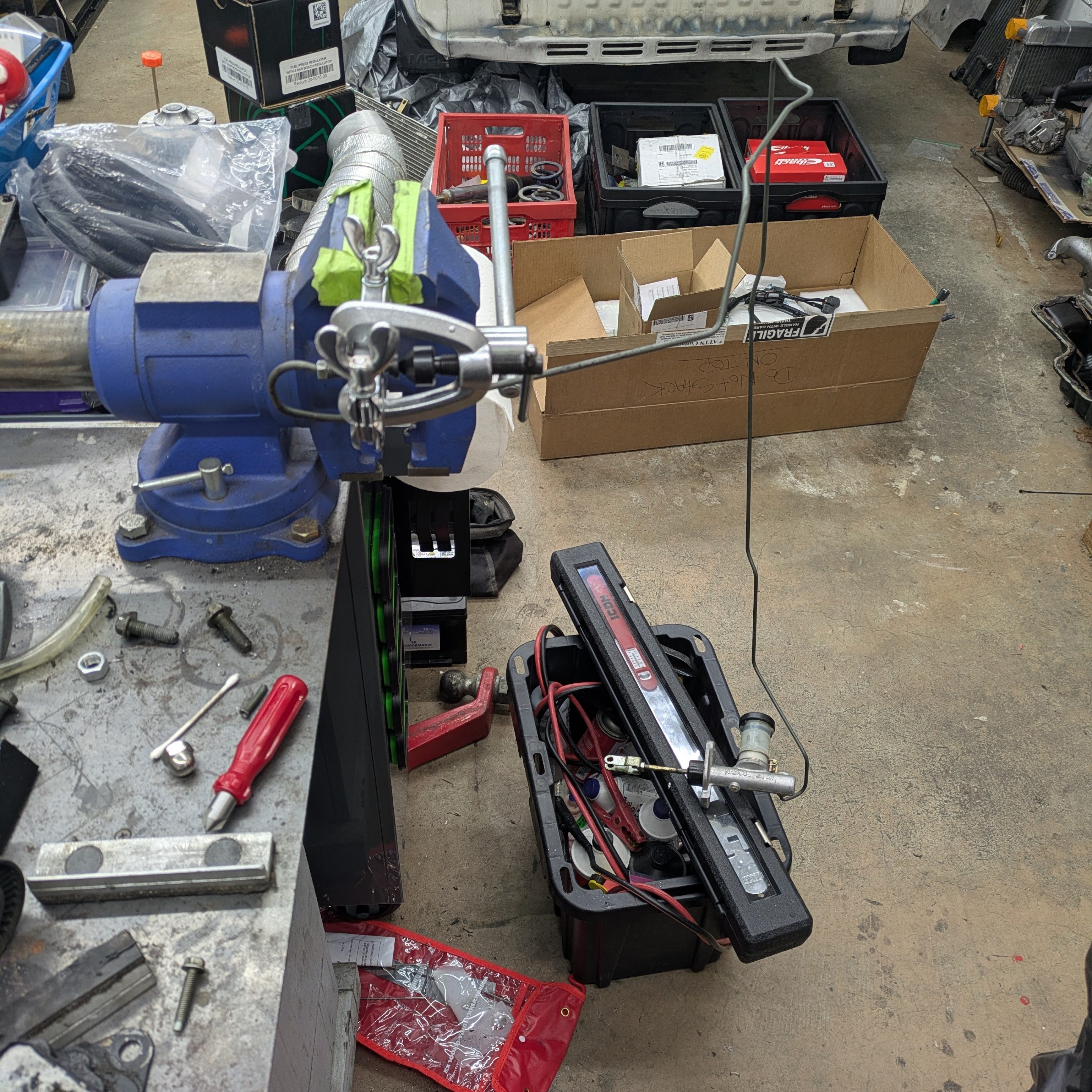
As some of you may know who have used those kits: they suck, and almost never work. This was my experience as well. Despite following the directions as precisely as an engineer can, it leaked from the flare as soon as I applied pressure to it. This is when mega homie Wolfgang, fellow brother in IS300, offered his Cal-Van flaring setup, which was the correct size and a much better flaring strategy.
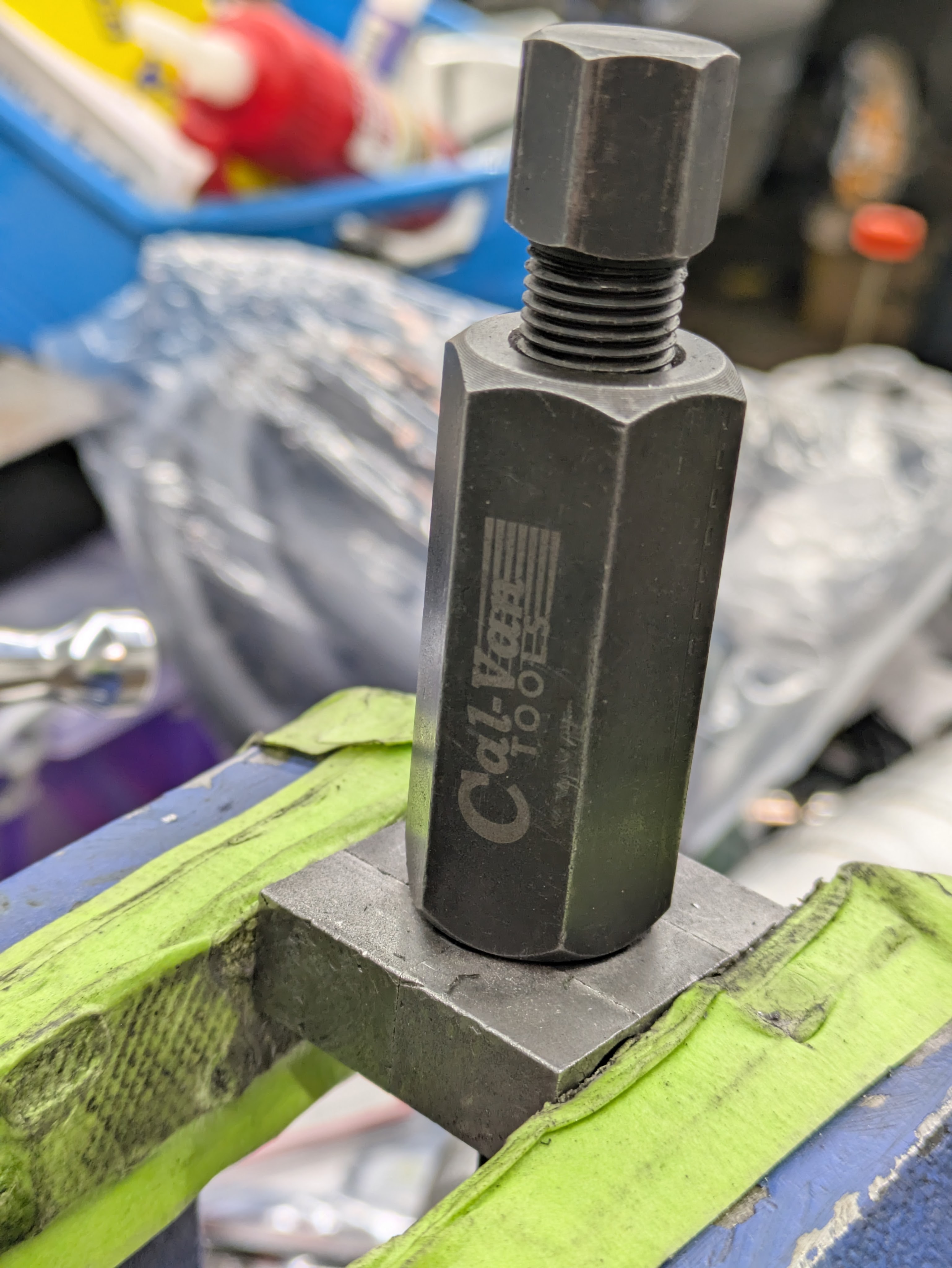
After removing the line and cylinder again, cutting the line even shorter, and reflaring it again, It worked perfectly and I was able to assemble and bleed the system. While probably (definitely) not worth it in the grand scheme of things, it was one of those “live and learn” moments of getting in deeper than I wanted to be, but it all worked out. The last thing to add to this system is a Nismo Big Operating Cylinder (the larger slave cylinder sold by Nissan specifically for the Coppermix clutches), and I am hoping to source one of those while I am in Japan this summer.
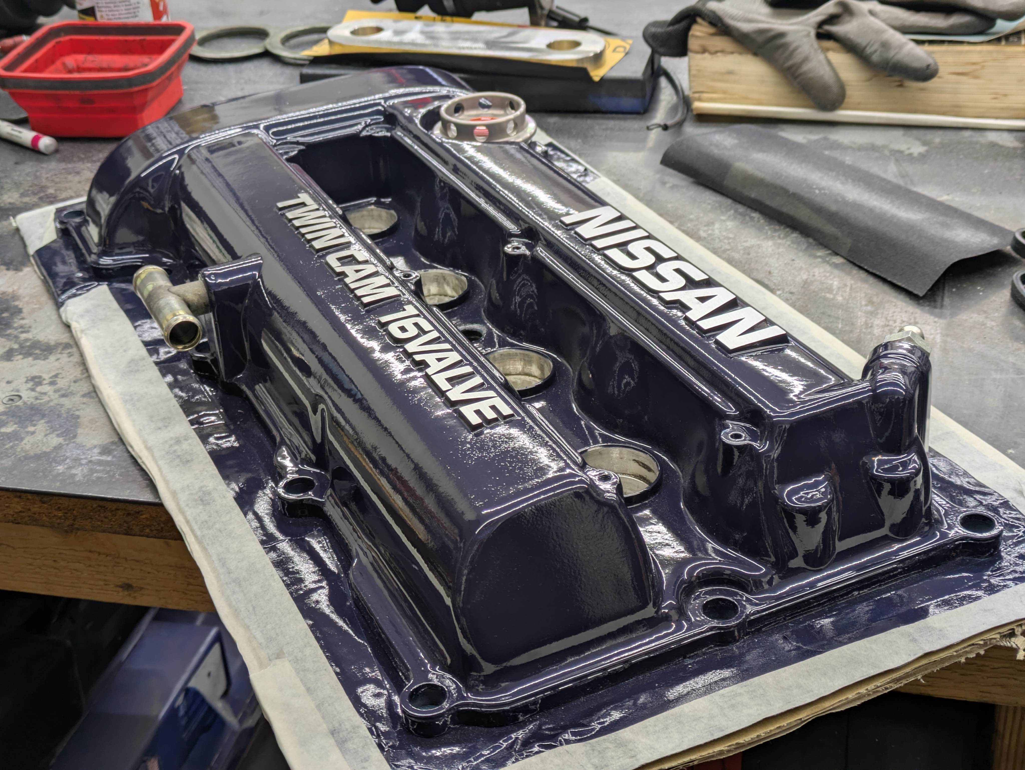
I intentionally left the final/pretty valve cover off until after the engine install because I didn’t want to be worried about the chains scratching it on the way in, but now that it is sitting in the bay, it was finally time to add some sauce back into the bay. To go along with the primary accent color of blue, I decided to paint the valve cover Nissan TH1, or Dark Blue Pearl. This color came on S13s and R32s in period, and is a deep, rich blue with a nice flip when light hits it. My sister was kind enough to perform the labor of painting it for my birthday (I provided materials) and it turned out spectacular.
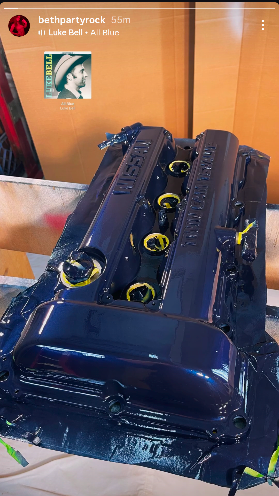
I gave the paint a few weeks to cure before I sanded the letters down to the bare aluminum finish, with flat stone and some medium (I believe 600) grit sandpaper. After a layer of Metal Coat (I’ll talk about this more later), it was time to install and lock in the motor for good; no more borrowed cover with stripped paint.
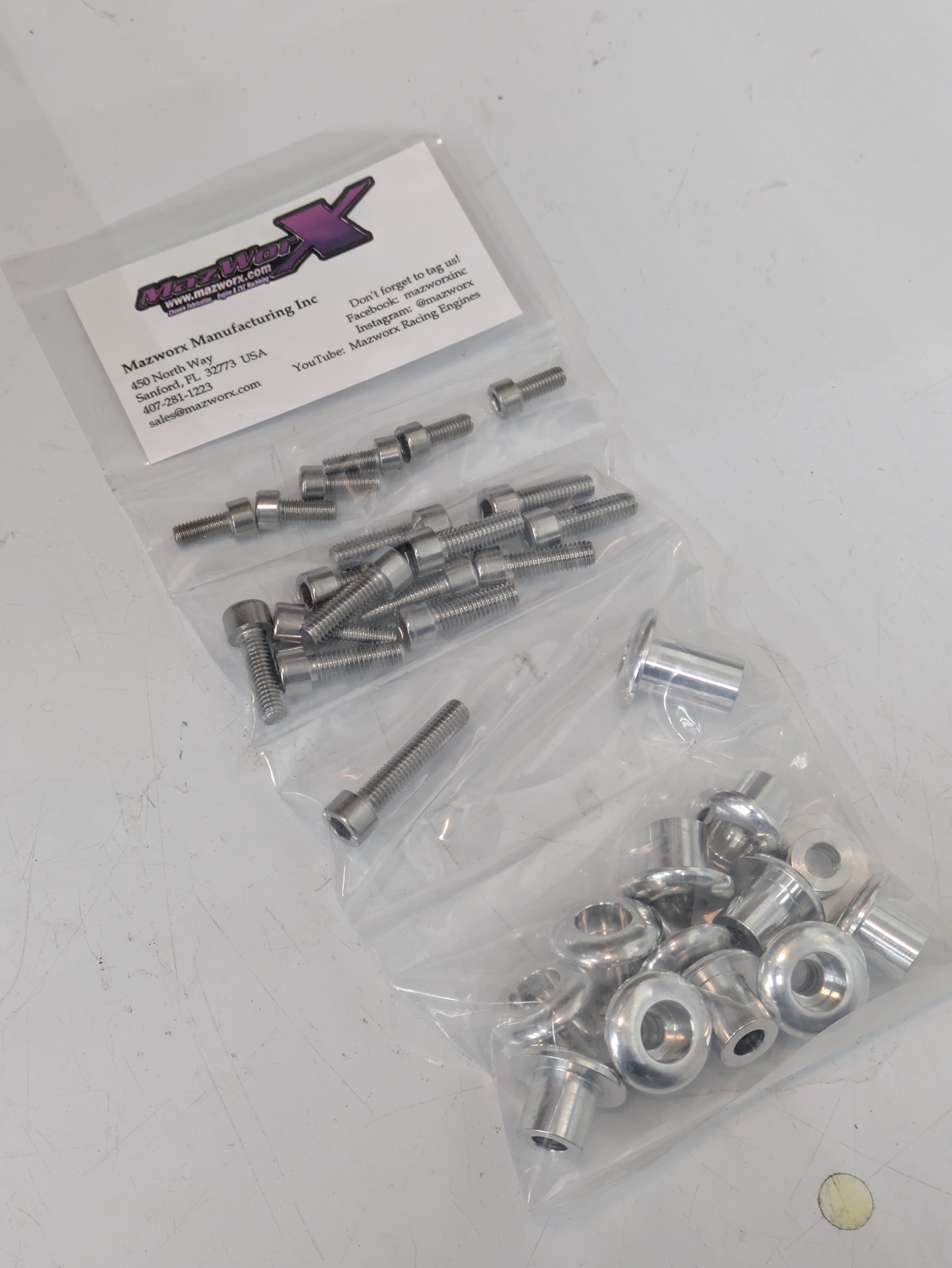
The OEM valve cover gasket and tube seals came from my gasket kit, and with some RTV on the half moons, it was time to bolt it down. As is to be expected on pretty much every SR20 at this point, the factory rubber grommets were pretty trashed, and the nuts pulled a few of the studs out with them. While I am generally a proponent of studs, especially when it comes to steel fasteners torqued into aluminum, there are many individual parts to those assemblies and I would rather simplify it if possible. The Mazworx hardware is the solution to my problem, and while not only being a beautifully machined piece, they also have a hard metal/positive stop so that torqueing the valve cover is far more consistent. While good for sealing, it also makes it much more difficult to break the ears off of the corners of the cover, which SR20s have an reputation for doing when not installed properly (by idiots, primarily).
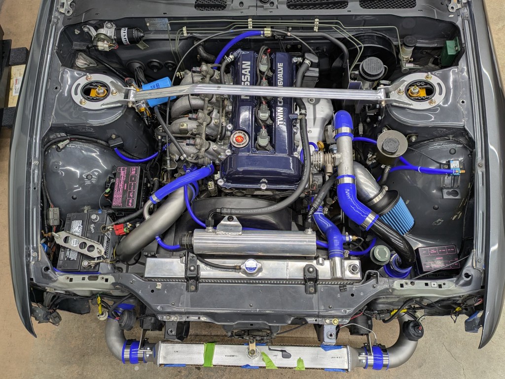
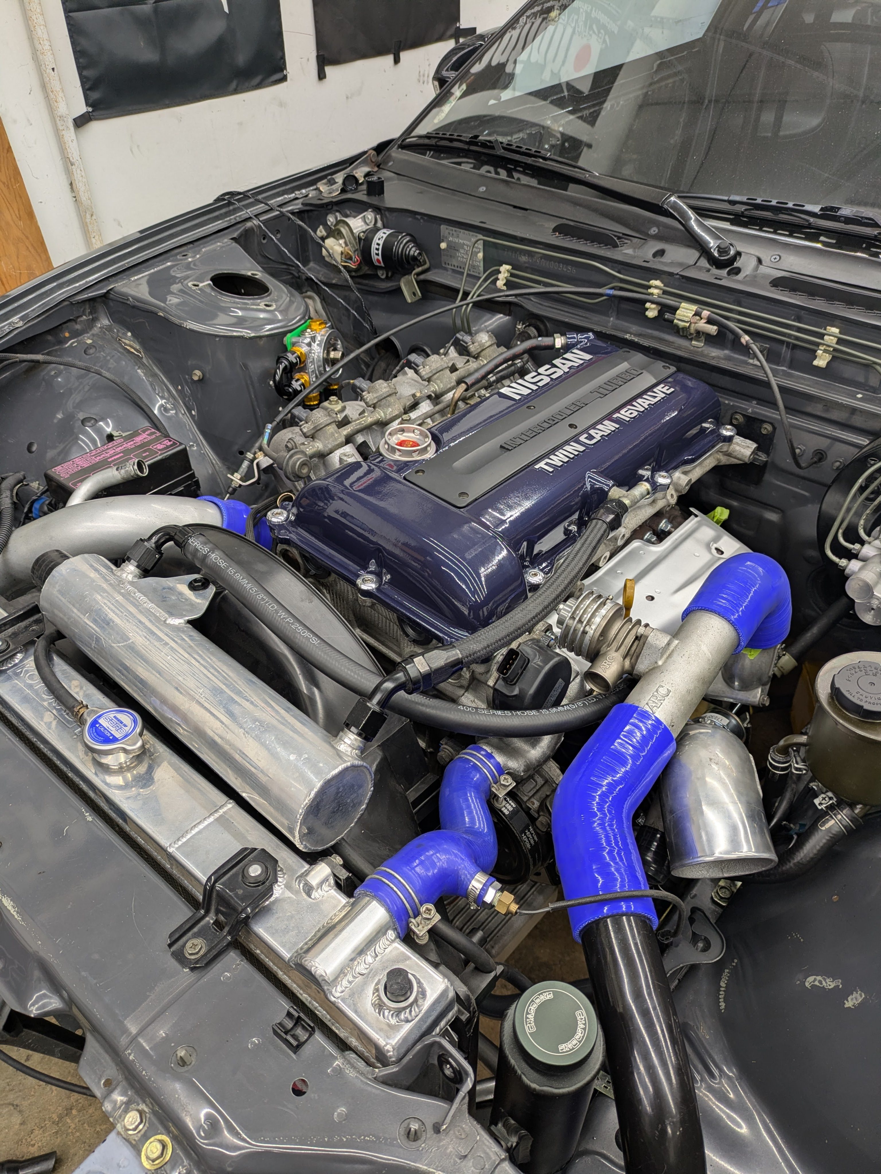
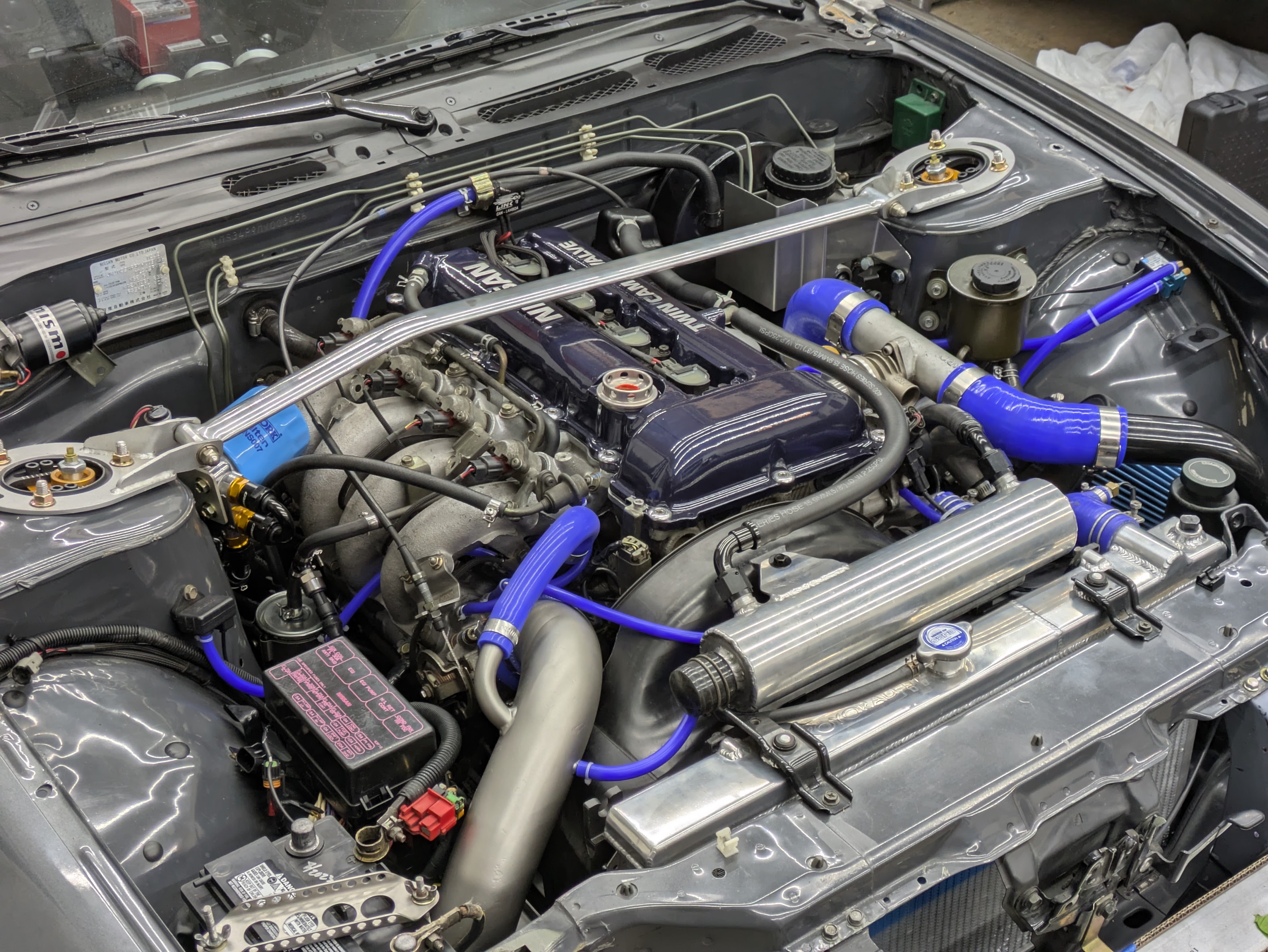
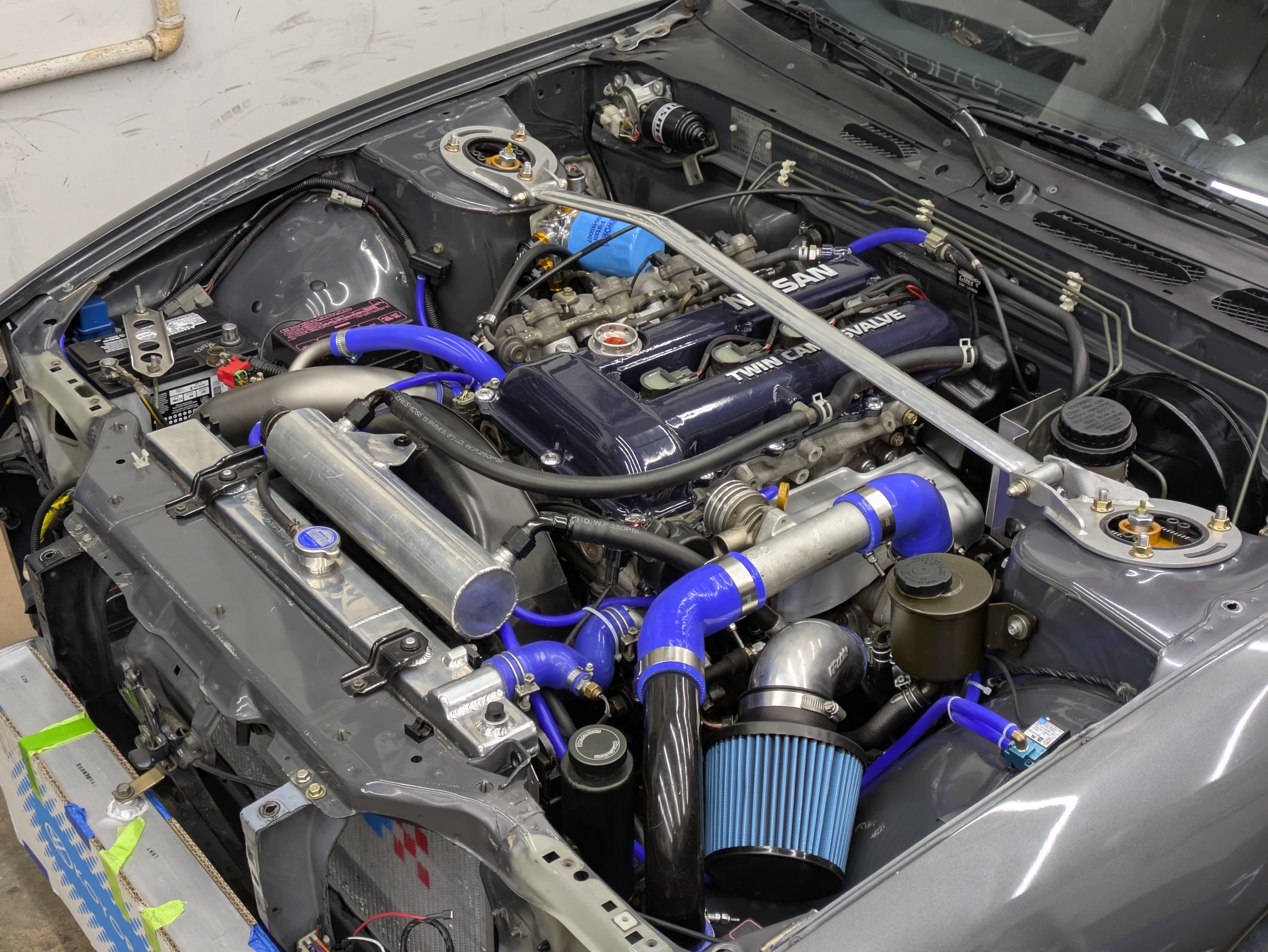
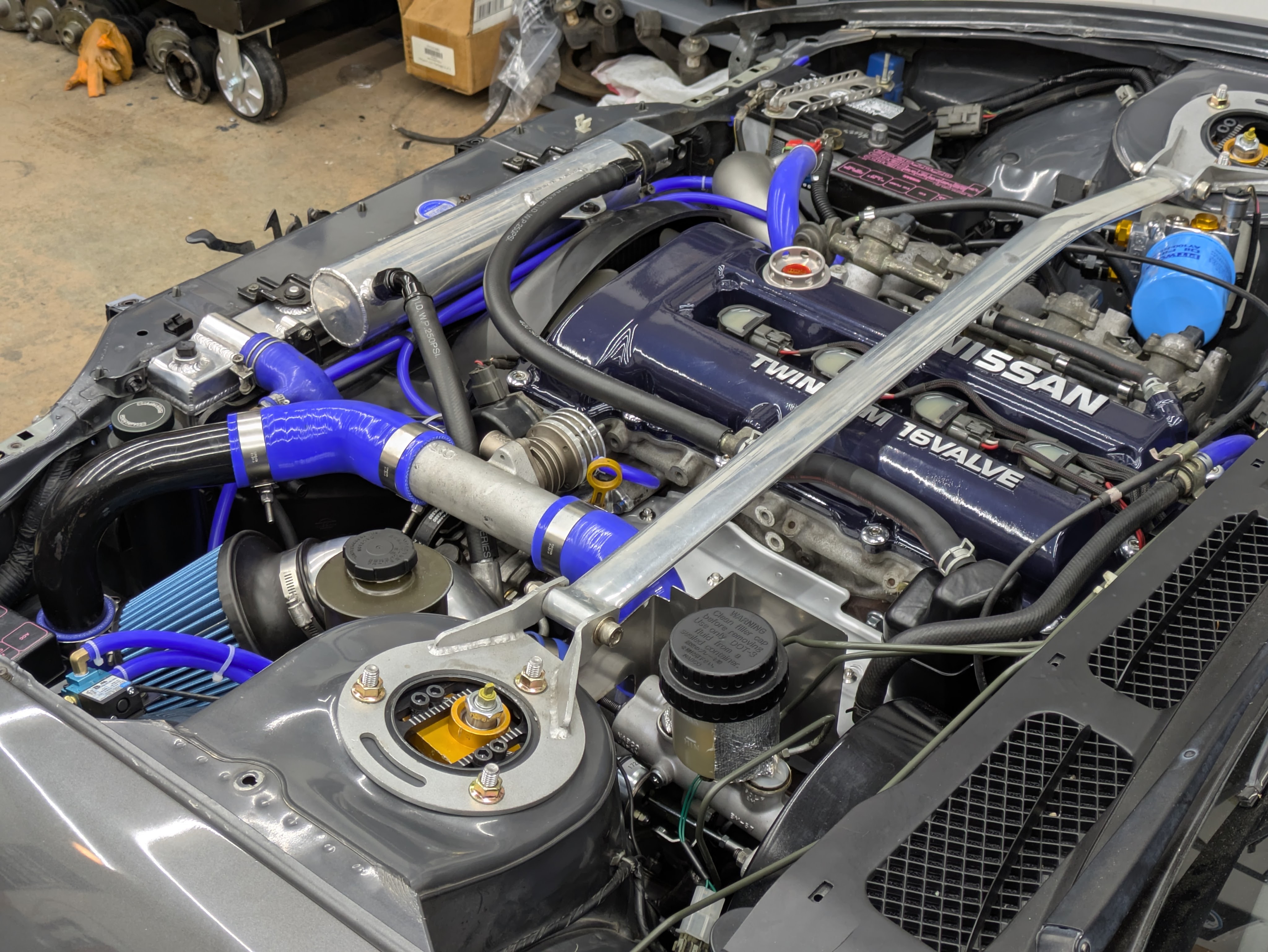
With the hardware installed, I was able to stand back and get an idea of what the general vibe of the bay wouldbe when completed, and I am oh so happy with it.
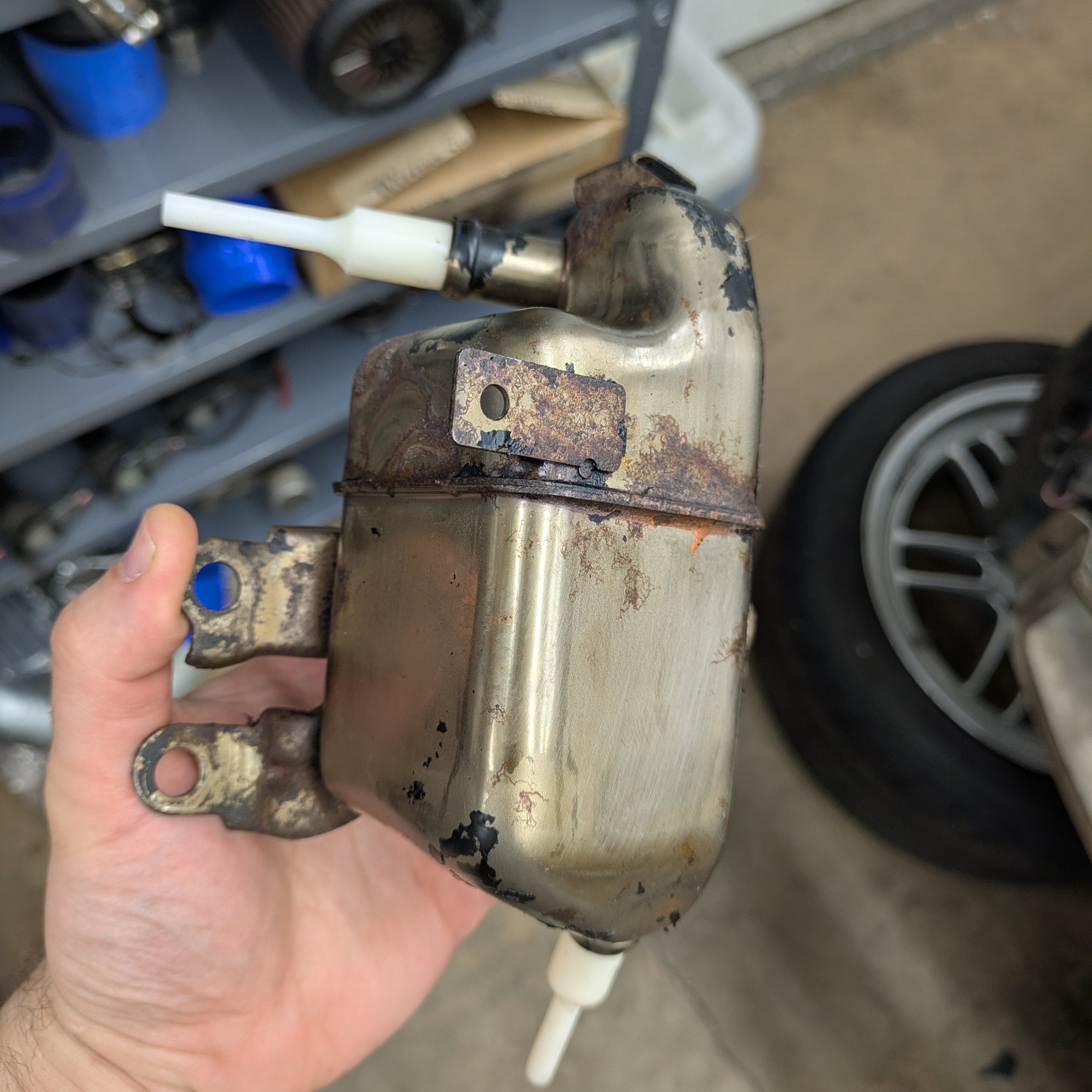
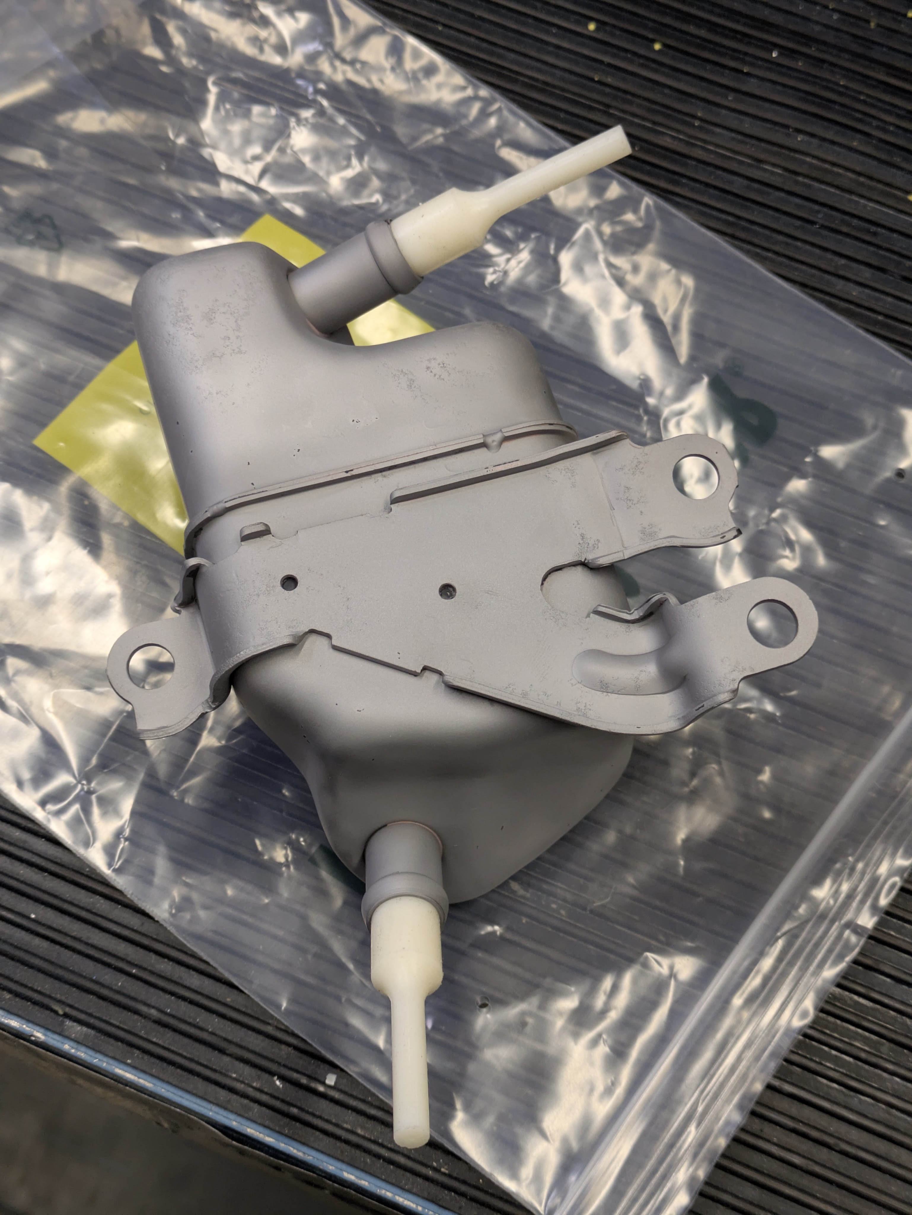
Back to plumbing for a bit. Half the reason I converted back to stock exhaust manifold was to be able to run the OEM air oil separator, which is the majority contributor for S13 oil control. I was locked in to a pretty consistent schedule with my powdercoater, and as a result, this ended up in it. I had previously stripped the old paint off when I stripped the valve cover, and I knew I wanted it to look right in the bay once it was all cleaned up. I don’t like the look of high temp paints, and while the temperature ratings of powdercoat can get dicey, I knew it was the best option and the easy button.
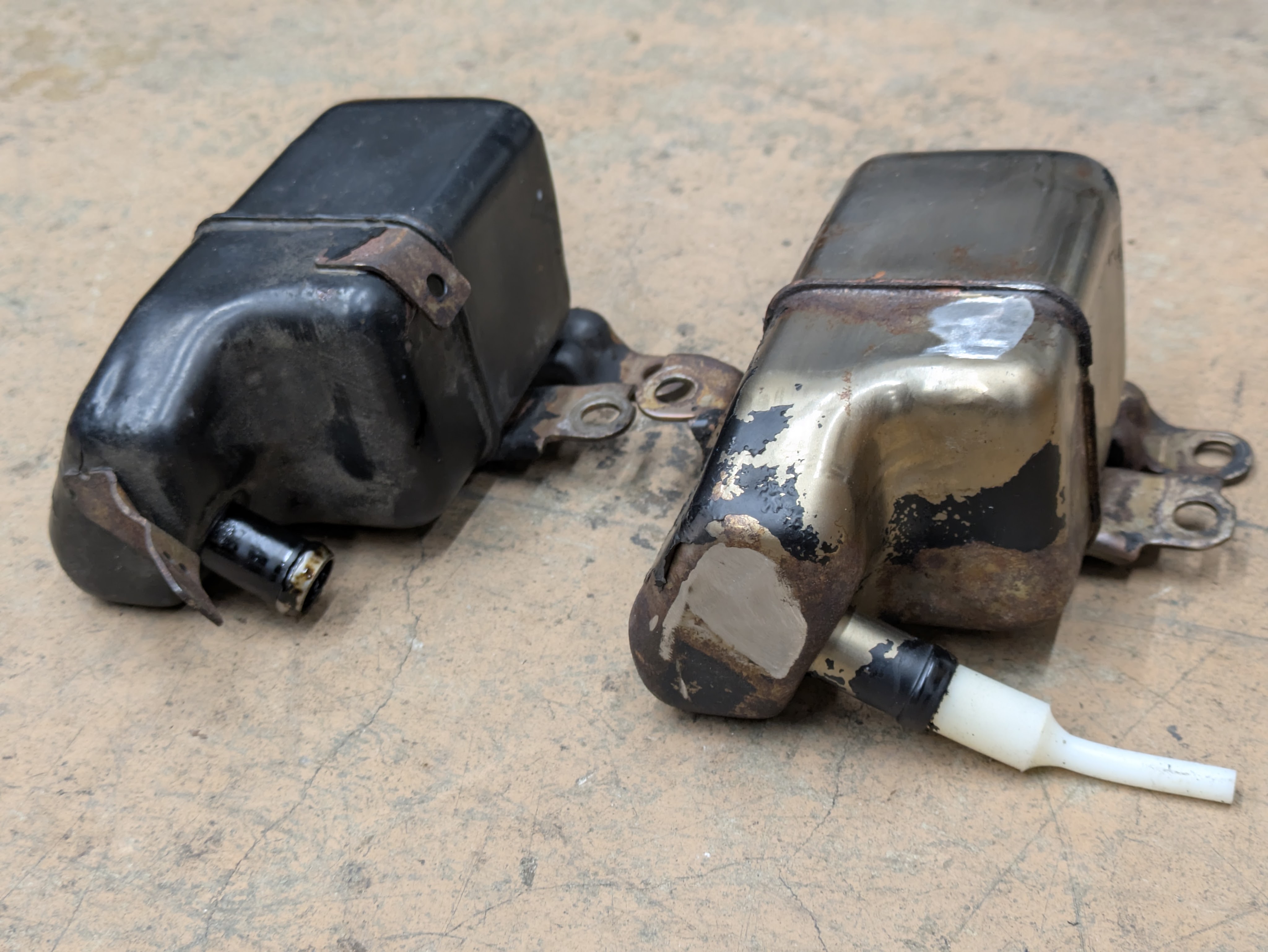
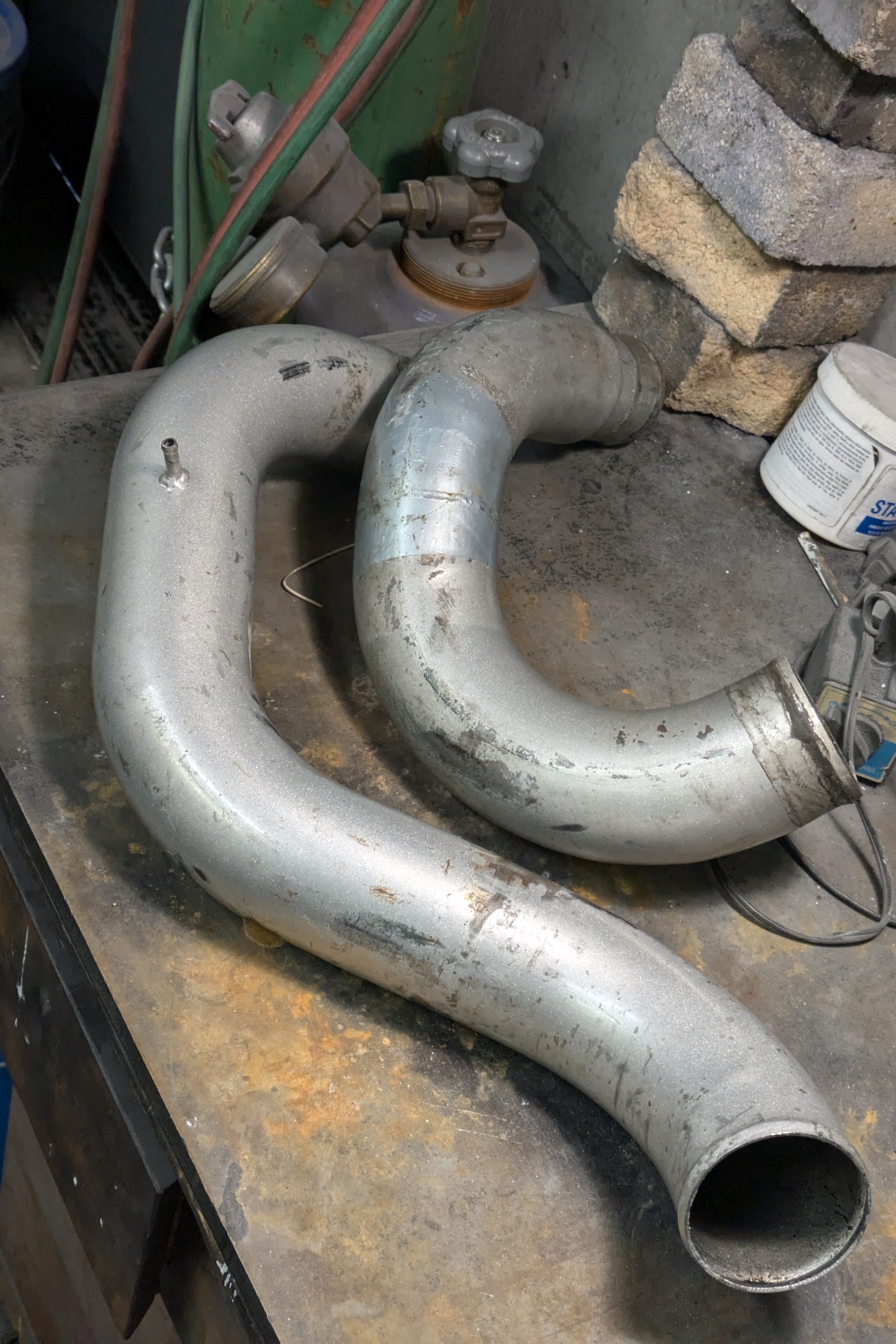
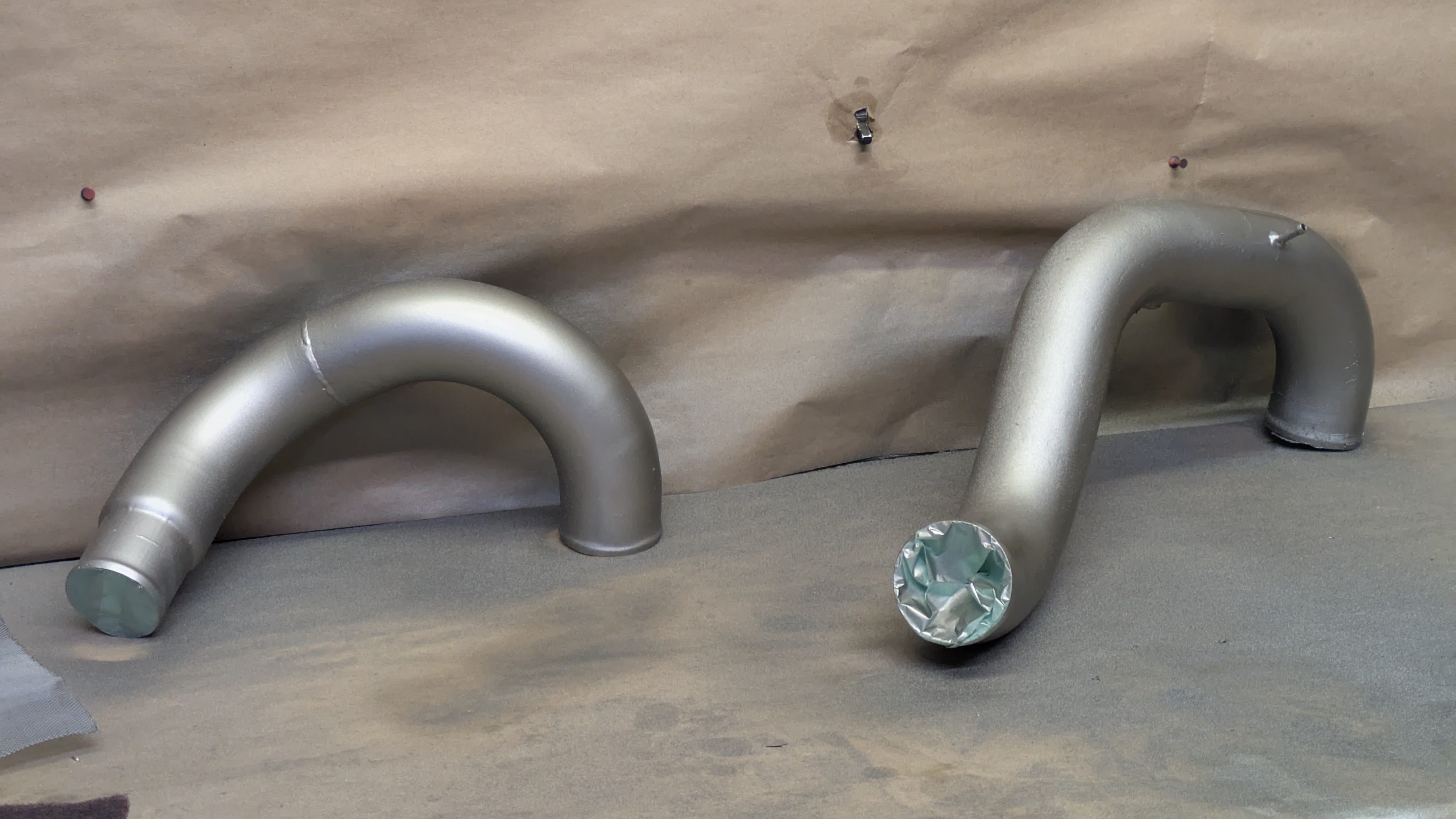
I found some perfectly fitting tapered plugs at work so I could sandblast it without worry, and after it was fully stripped, I decided to shave the unnecessary brackets off of it before it got coated. This can be shown in the side-by-side above. This is a really small detail, but one I really like. It’s gonna take a mega nerd to spot it if they don’t about it here (my ode to VWs I suppose). It is also worth mentioning that when the engine was out, I spent the few minutes to mock up the AOS and realign the metal hard pipe drain hose with the outlet, as these pipes are thin wall and can easily get knocked around. Even the OEM drain hoses end up with a slight jog in them, but mine was perfect after correction.
With the engine install progressing, it was time to pull out a box I have been sitting on for almost a year.
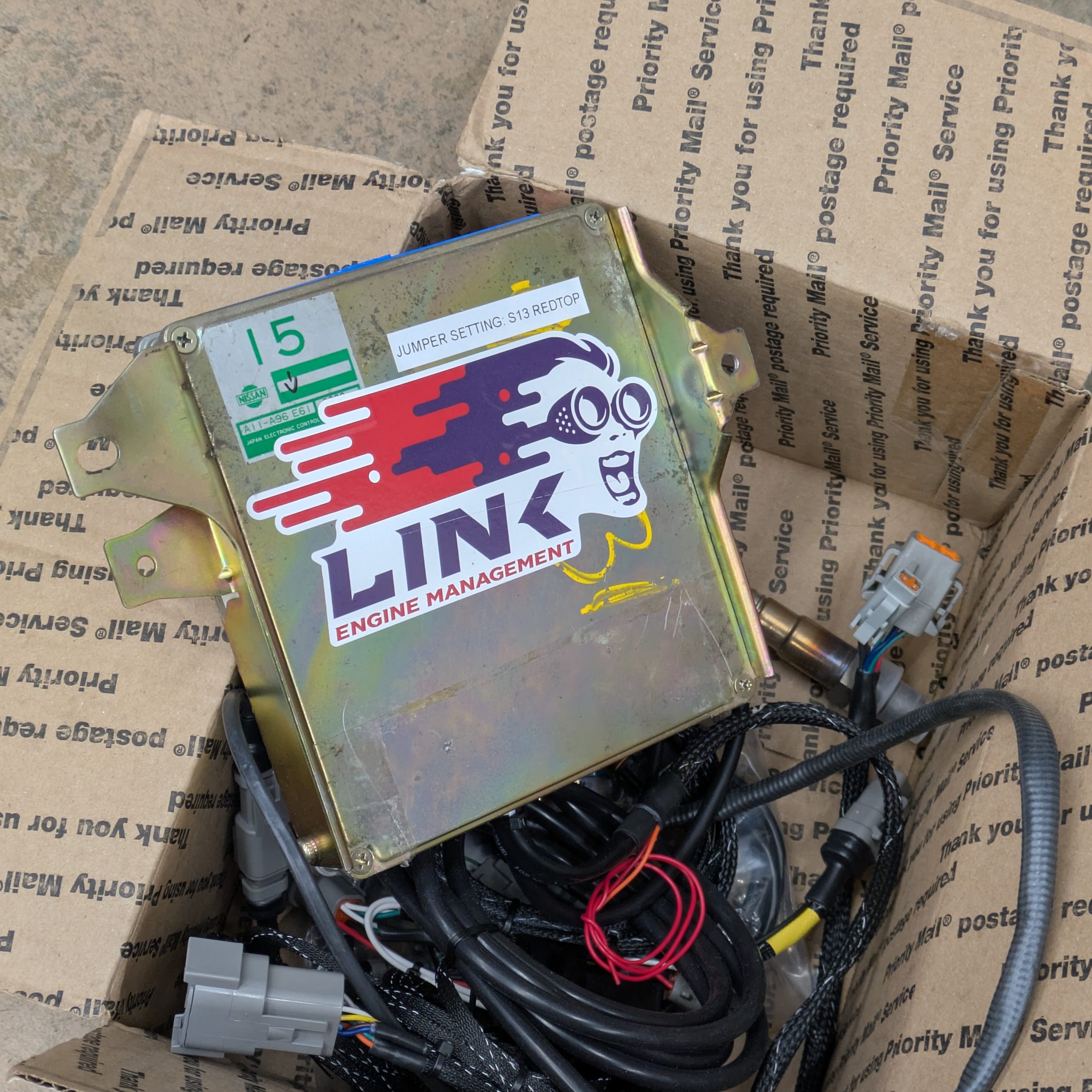
As soon as I had bought the car, I knew the RS Enthalpy ROM tuned stock ECU wasn’t going to stick around for a long time. While it ran fine (one to two points on the richer side during every load condition), the rising cost of SR20s starts to justify upfront investment to keep it alive. I had the option to buy Luis’s Link when I bought his motor, but I opted to keep mine since it was more optioned out. I called Mark Panic at Panicwire, and an order was placed.
I ended up with a Link NS15X Plug and Play board, which runs pretty much all of the SR20s with a few jumper configurations. Without asking, Mark ordered me a Nissan Stanza ECU off eBay, which is the identical case to an S13, and made all of the necessary mods to install it with the integrated map sensor outlet and CAN features. The second housing allowed me to sell my ECU with my engine setup complete and untampered. Mark is a real homie.
It didn’t stop at an ECU; if I’m doing a standalone, I am going ALL the way in. On top of the required GM IAT to run Speed Density, I opted for Bosch CPTS (Combined Pressure Temperature Sensor) for the oil system, fuel pressure sensor for safety and modeled fueling, CAN Lambda for direct-to-ECU AFR input, 3 Port MAC valve for boost control, and a Link CAN Gauge to monitor sensors in the car. Is it overkill? Depends on who you ask.
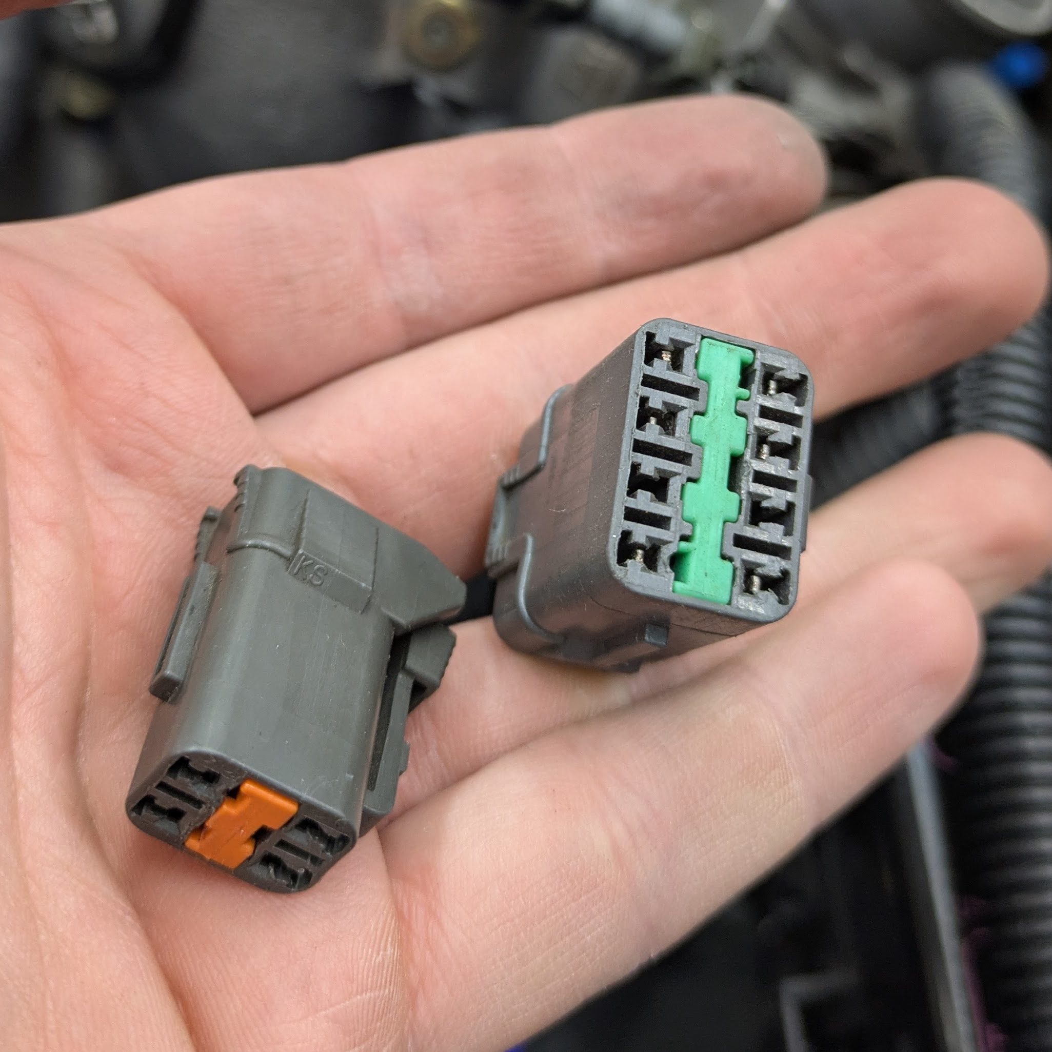
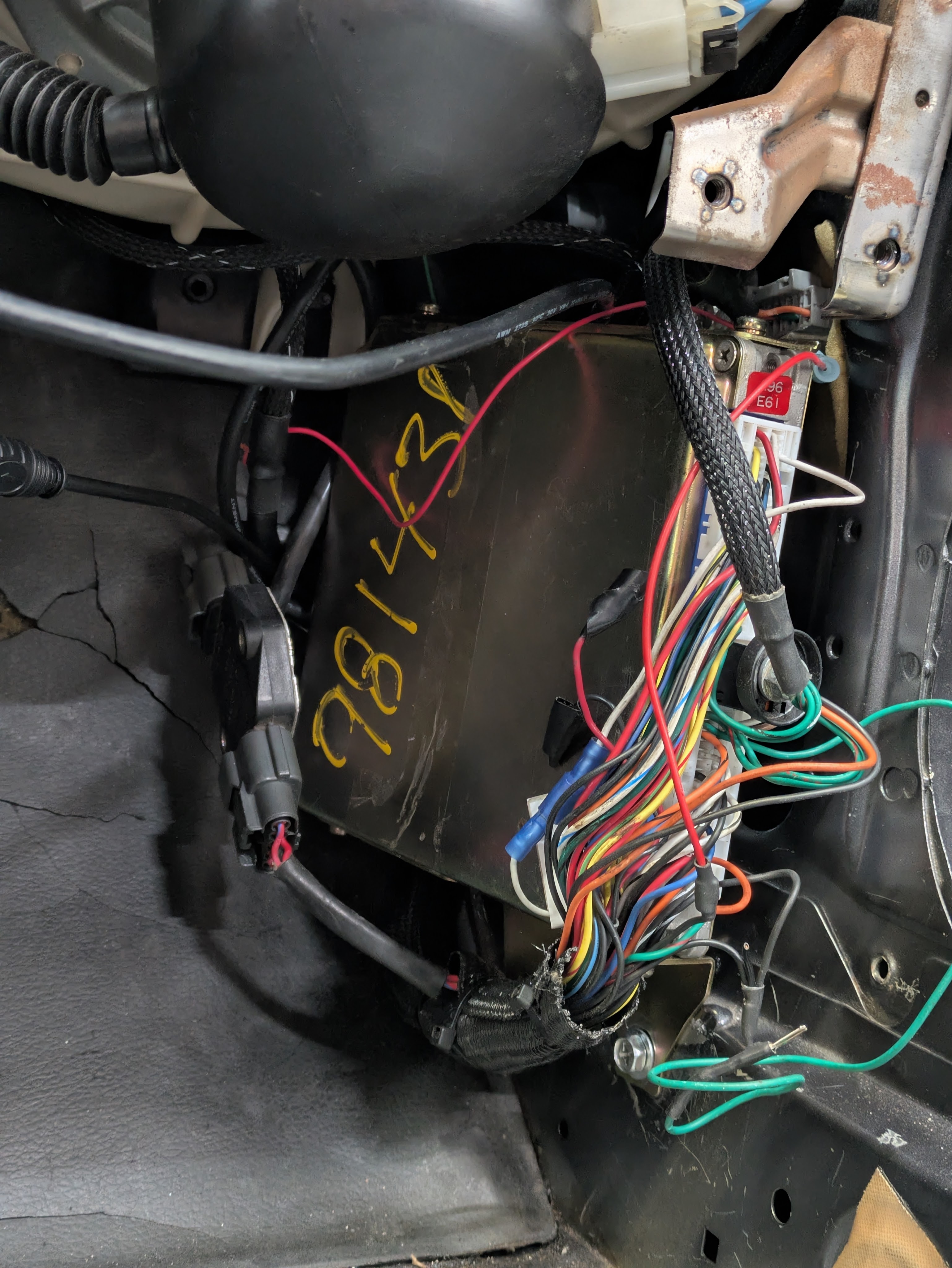
I was fortunate to acquire a Wiring Specialties Pro Harness with Luis’s engine, which entirely replaces the separate engine and transmission harnesses as one slender, integrated unit. This caused a few foibles as I didn’t have the actual documentation for it even after emailing WS directly, but fortunately the modern harness directions were sufficient to figure out what I needed to do. It plugged in and routed great, and only needed a slight re-pinning of the pictured 4 and 8 pin connector due to my car being factory manual vs Luis’s auto to manual.
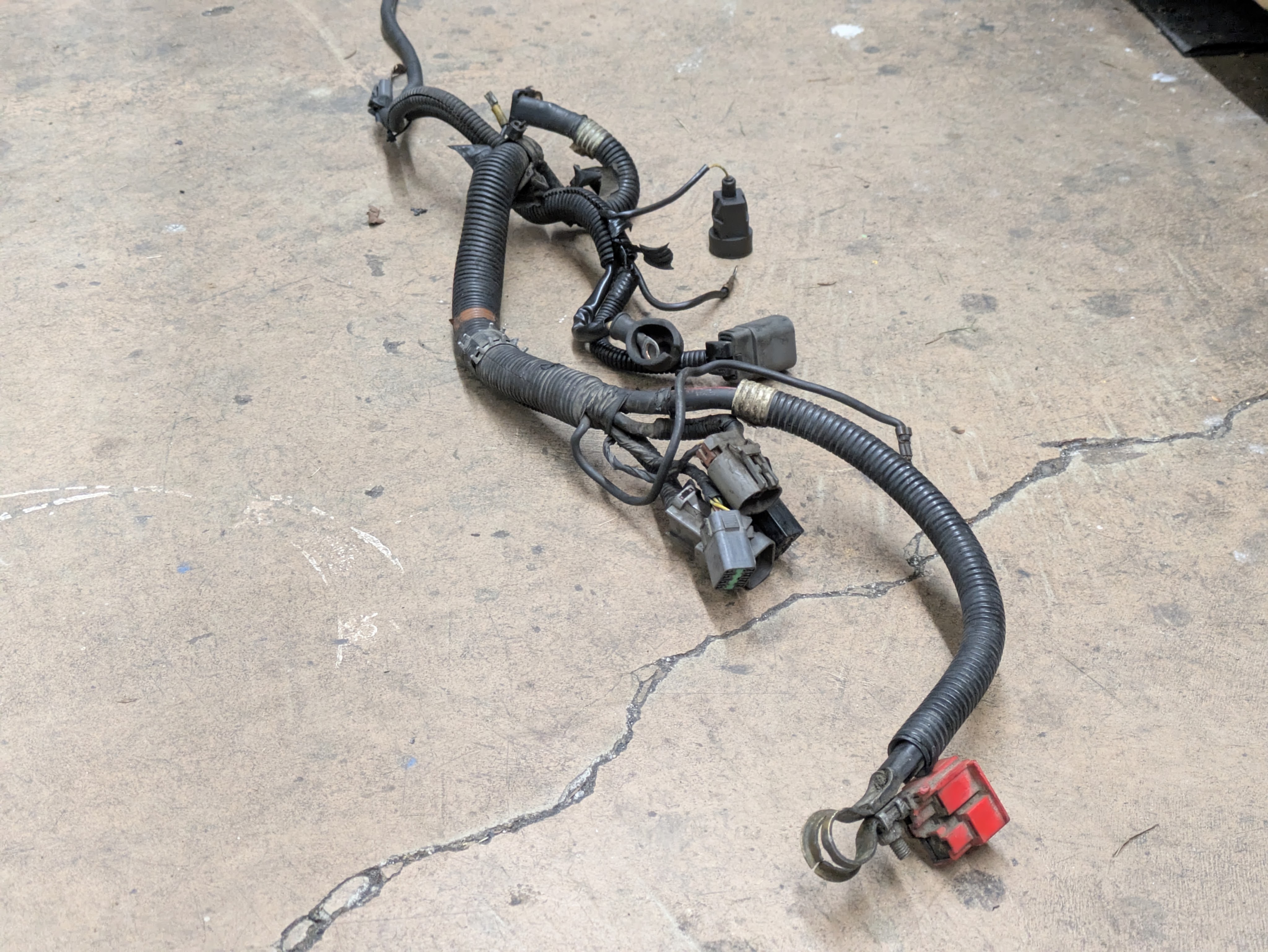
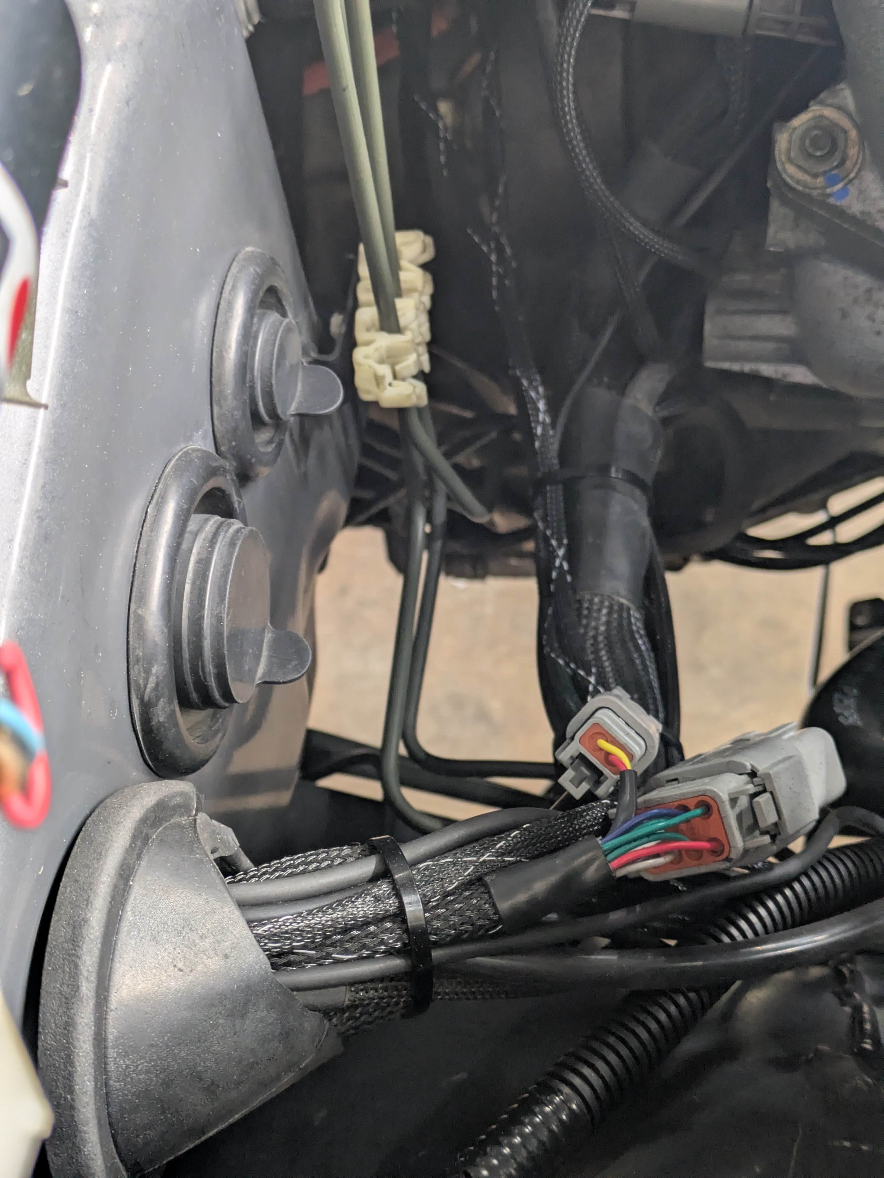
I took it upon myself to route everything in the most tucked and clean way possible, which lead to pulling the connector through the firewall twice as I missed which gap to shoot on the HVAC fan box the first time around. After a lot of deliberation and zip ties, I was able to get everything exactly where I wanted it. The factory oil pressure switch was deleted in favor of the CPTS through the CAN network (I also didn’t have a place to put it due to the Defi sensor), but fortunately the lead was long enough to put through the firewall grommet and be hidden away. The firewall is sealed with an OEM style firewall boot which was both slit to pass the wiring through the side, as well as trimmed as there are significantly more wires exiting it than factory. It was good to get that system finally tied up.
While not significantly degraded, I opted to replace the fuel softlines while I was already deep in the bay. The one mechanical regret I have on this car is not dropping the tank to replace the rear fuel lines, but they looked to be in great condition, so I was far less motivated to do so. Either way, should have let the snowball happen so it could have been 100% new in the perishable areas.
With the addtion of the Link ECU, I was able to add a fuel pressure sensor to the circuit. One of those modern additions I was happy to welcome, especially since it allowed for modeled fueling and greater safety parameter coverage. Also, when Mark Panic doesn’t give you a choice, you don’t argue. I used an Earl’s 5/16 barb T fitting with the 1/8NPT for the sensor. I did miss on the first go-around and used PTFE tape not rated for fuel. I later replaced it with Permatex Seal + Lock, which is effectively PTFE thread sealant paste with blue Loctite strength. Neat stuff to have around, and fuel + hydraulic rated. I updated every clamp to a fuel injection clamp since there were a few rouge worm gear clamps in the system.
By this point, my final revision of my oil filter relocation bracket arrived, allowing me to make the hoses.
I’ve been a big fan of pushlock/barb style AN hoses since I did my first big oil cooler setup on my RX-8. Braided hoses have their place, but these just look a little nicer, and they are far nicer to work with. There is a chance that I do BMRS later on, but these work fine for now.
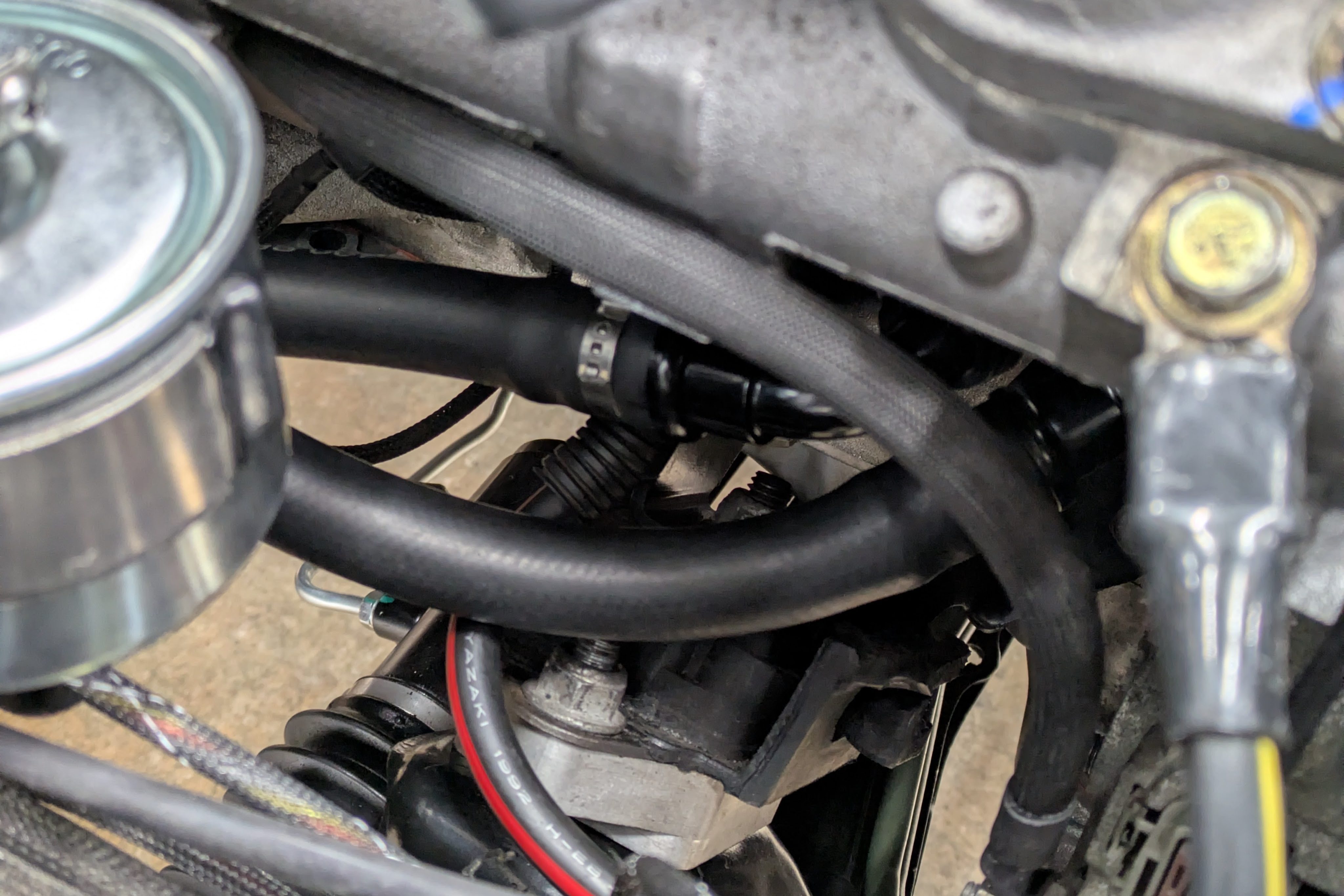
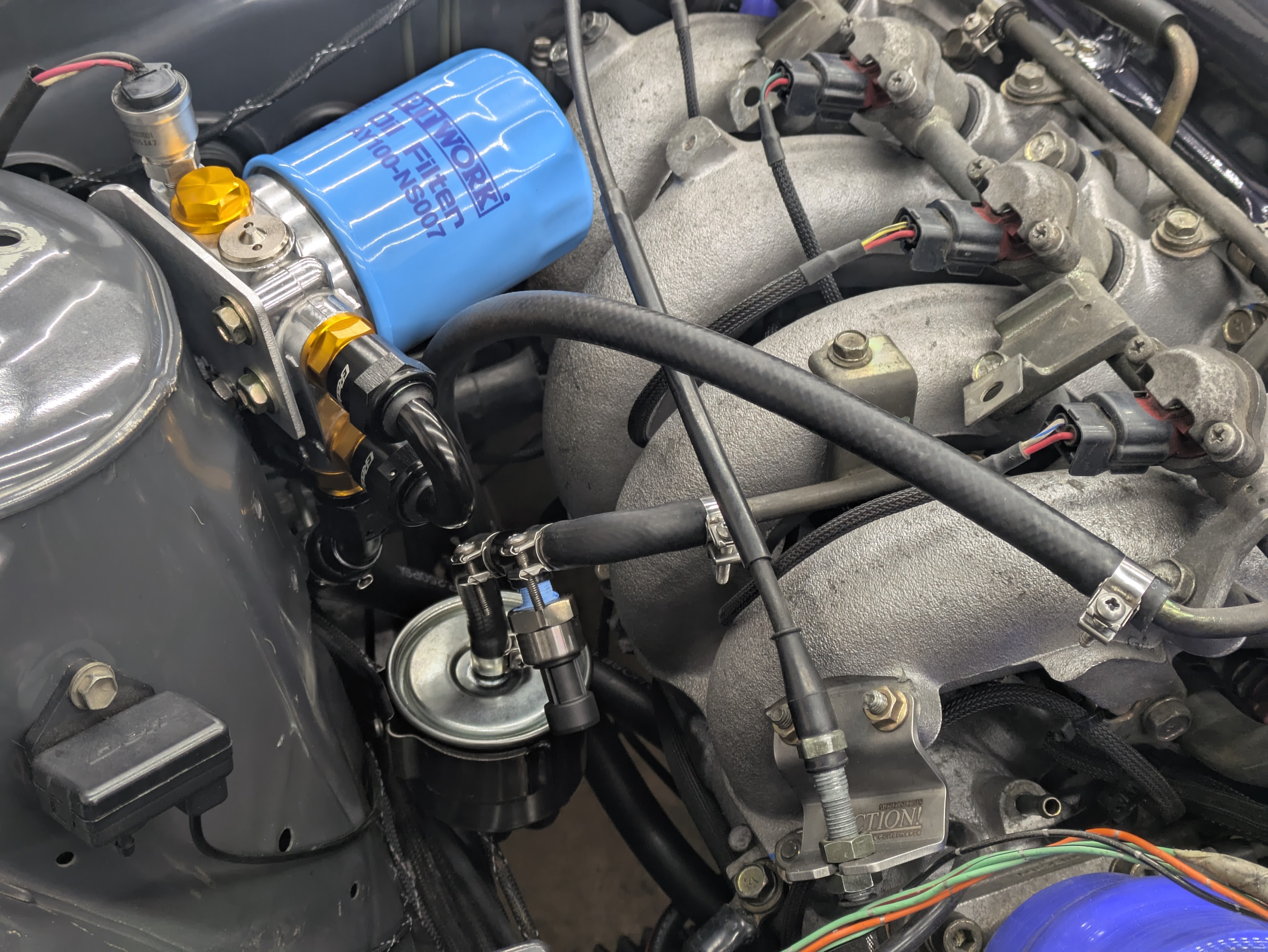
The routing turned out pretty clean, and nothing has strain or rubbing or near hot things. As long as they don’t come loose or give me issues, they are fine in my book.
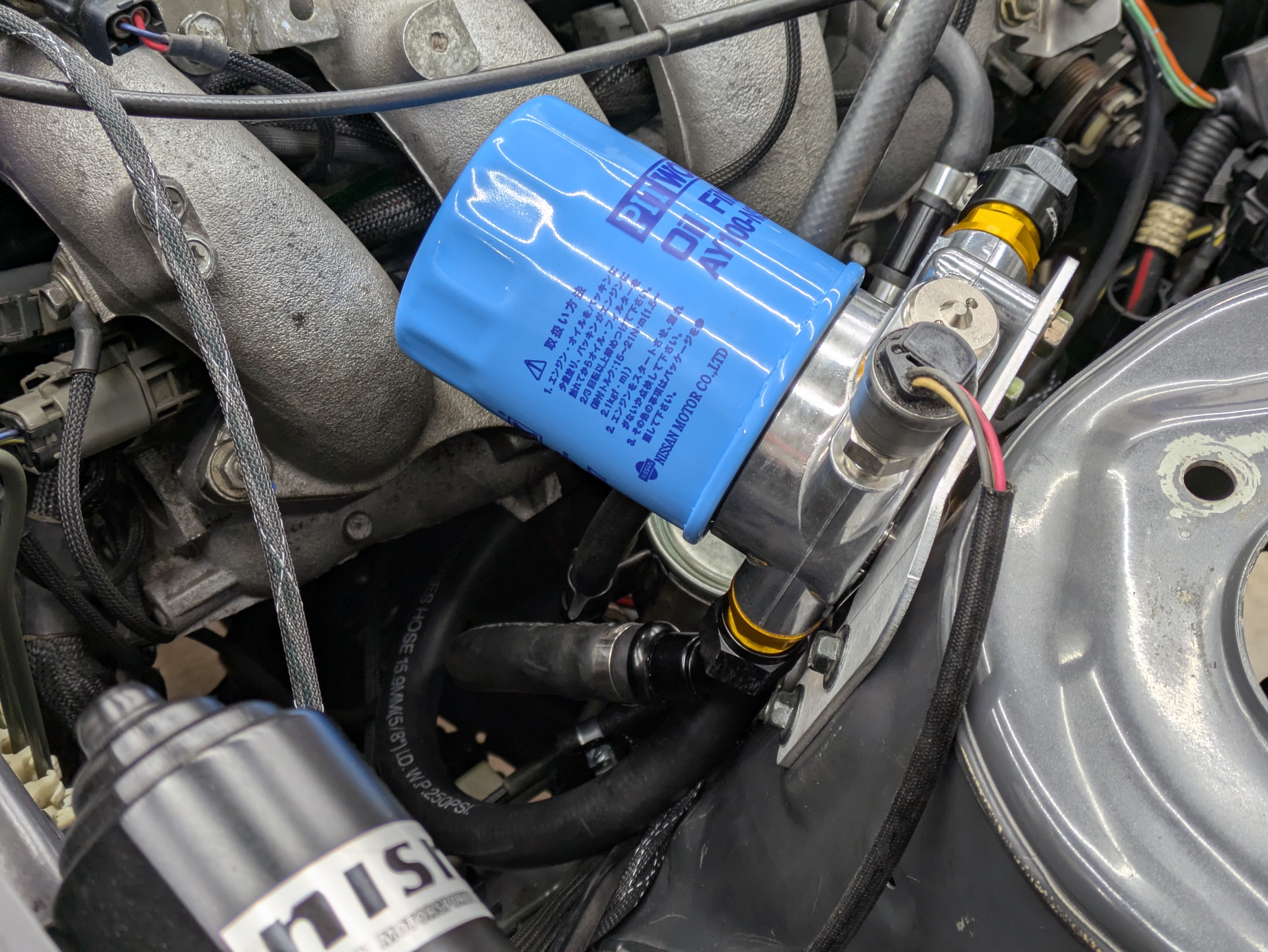
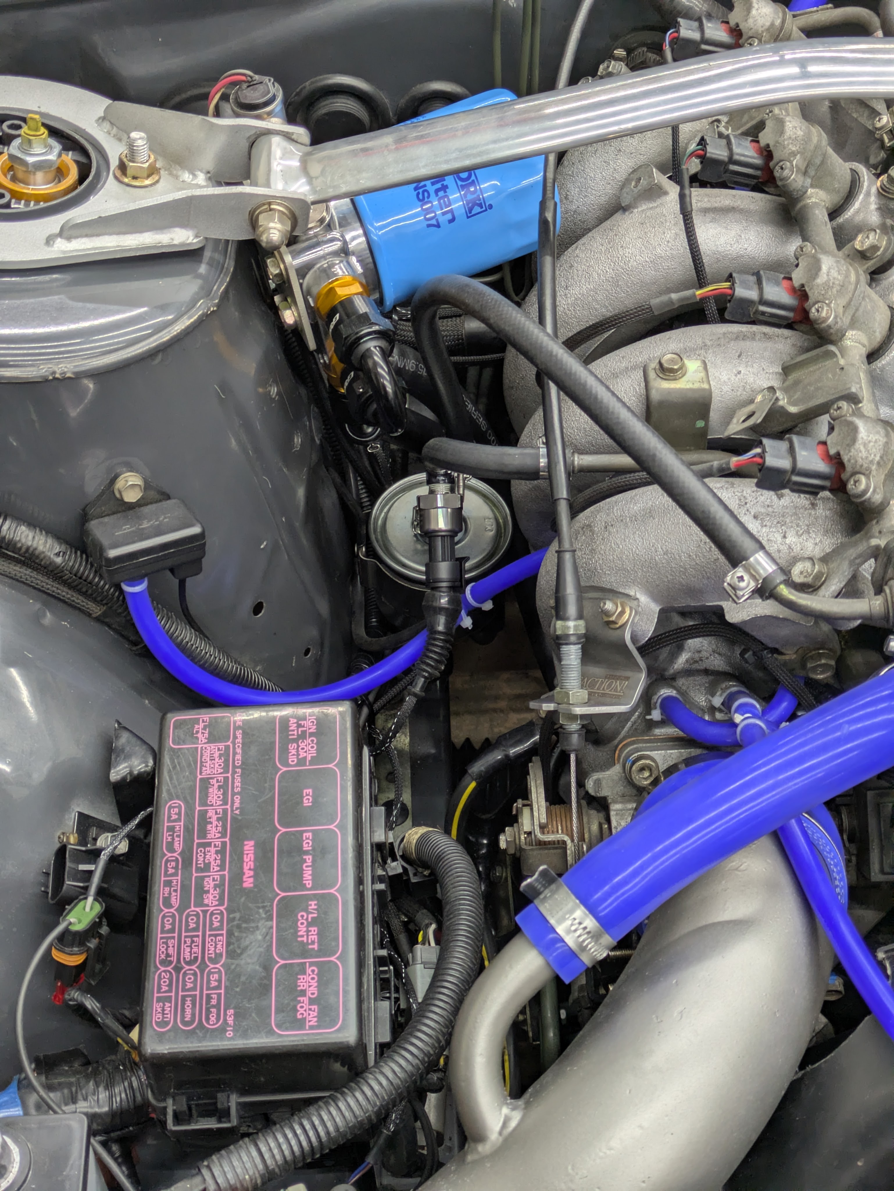
The oil filter itself was a nice OEM catalog find. These are OEM Nissan Pitwork oil filters and this one in particular fits the gasket landing area and matches the 3/4-16 thread (OEM early SR20) that I opted for with the Greddy, while having a gigantic filter area vs the OEM size. They go with the blue theme, and I am a sucker for OEM filters, so these were ideal. The part number is AY100-NS007 for those interested.
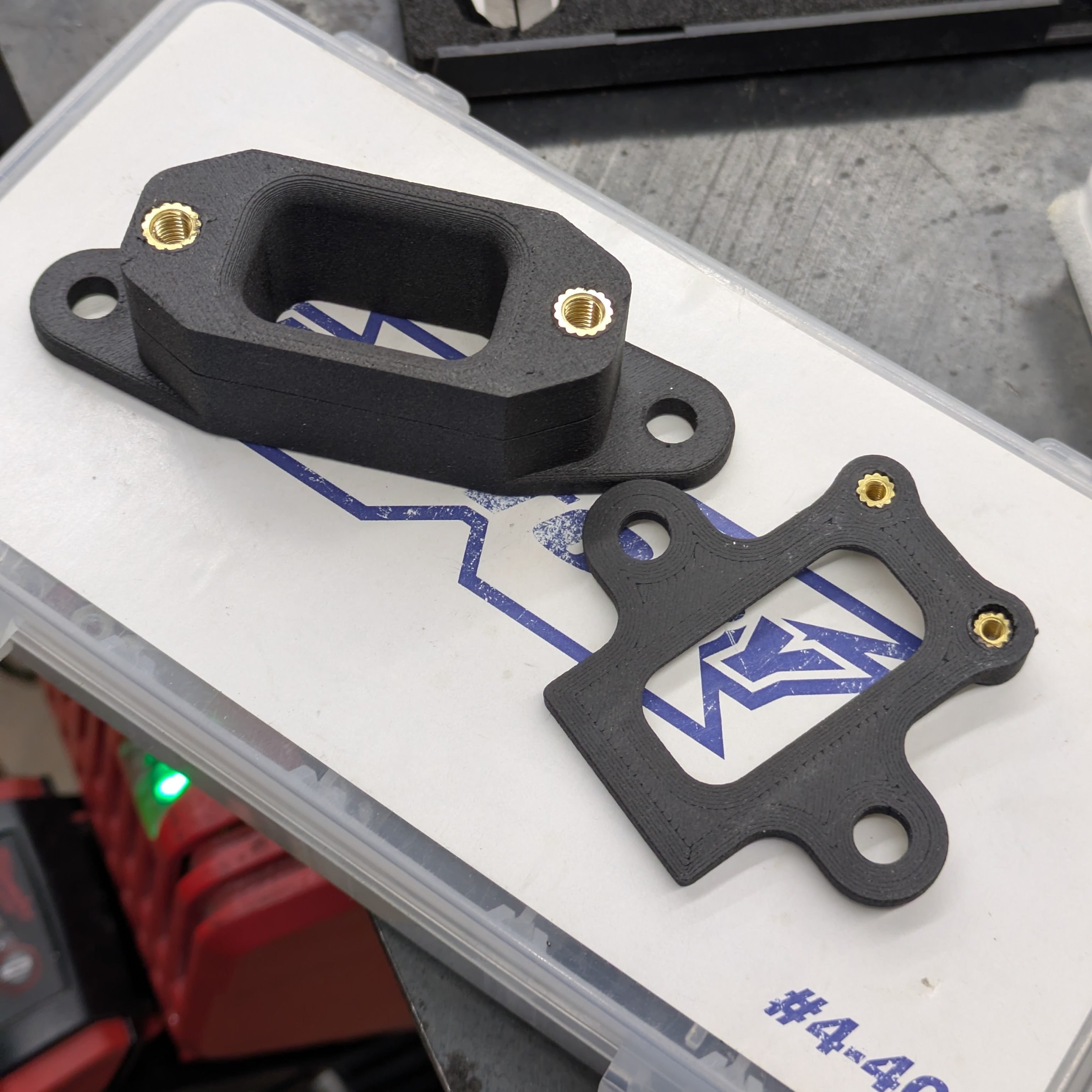
Given the scope of this project, it should be unsurprising that I went all-in on sensors. I had been debating placement of these units for months, but I waited until the last second to locate them so I wouldn’t have to move them later. They both settled into homes that didn’t require any wiring extensions or inconvenient routing. Both of these mounts were printed from PA6-CF, a carbon fiber reinforced Nylon with great strength properties and temperature resistance. While they didn’t take a heat set insert as smoothly as something like PLA does, it was the perfect filament for the job.
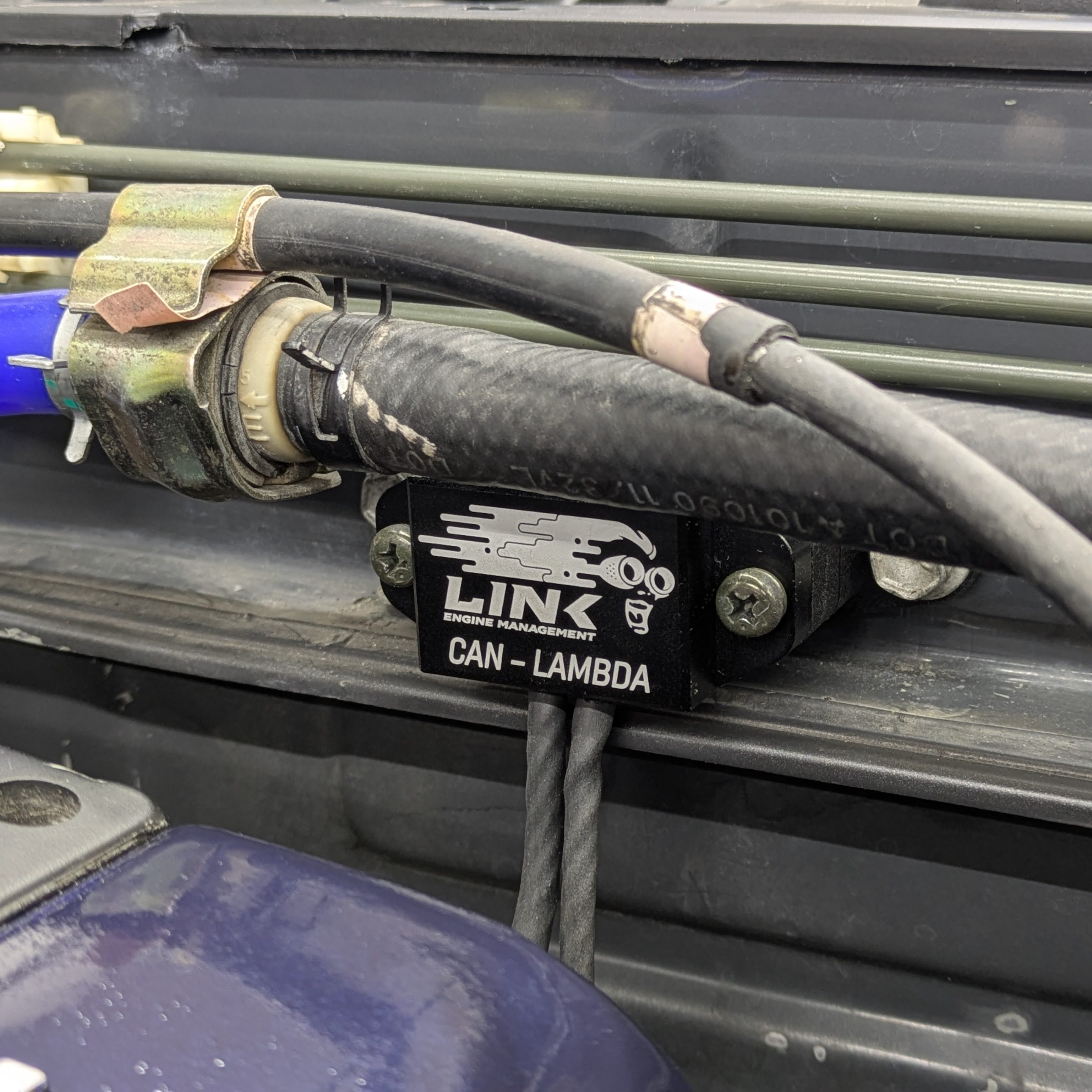
The Link CAN Lambda was explicitly chosen over the AEM because it had mounting provisions that weren’t zip tie slots. Yes, the nearly 100 dollar difference was worth it because it looked better and had mounts. I later learned from Mark that the Link units can actually control the sensor heater, where the AEMs, when hooked to the Link, run the heater all the time, so there’s my sensor longevity justification.
Either way, the mount ended up sharing a fastening point with the brake booster vacuum check valve, and another M6 hole on the firewall.
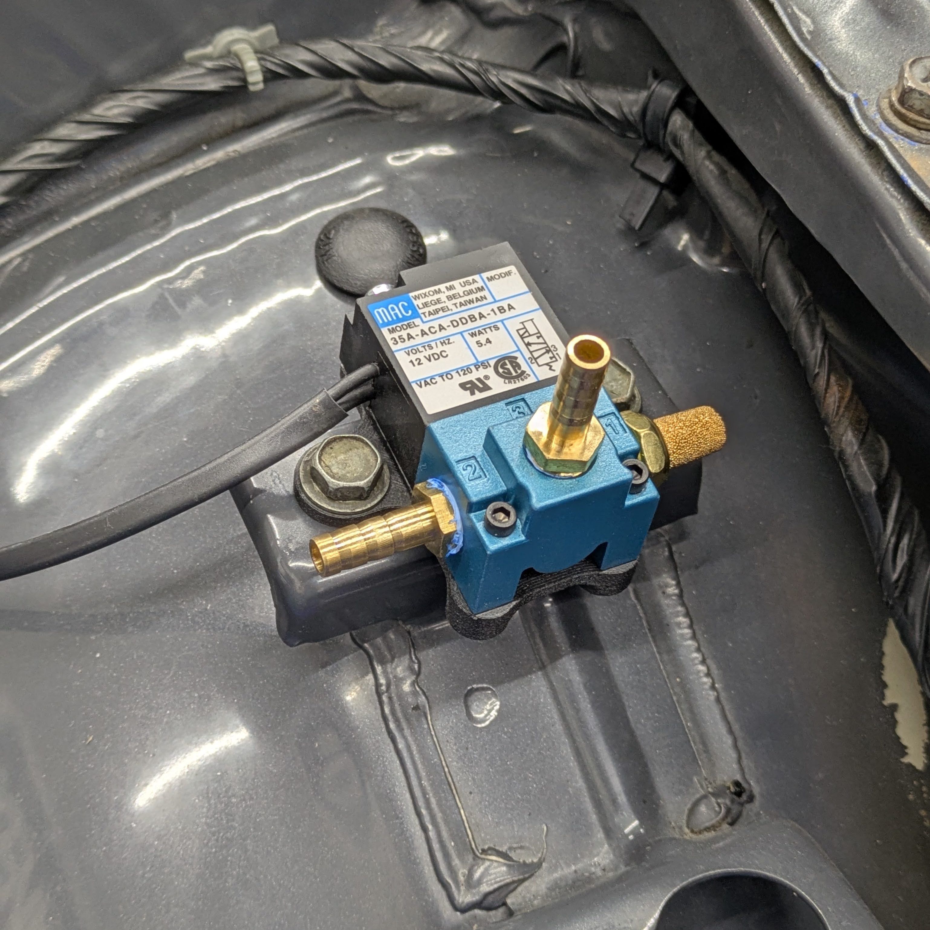
The 3 port MAC valve was perfect for internal wastegate boost control, and with some 10-24 bolts and heat-set inserts, it found a home on the old airbox mounts. It kept the high risk vacuum line short while being very out of the way, and the entire sensor away from heat and excessive vibration. I later swapped the #3 straight fitting for a 90 degree unit so the hose didn’t have to intersect the hood to hook up.
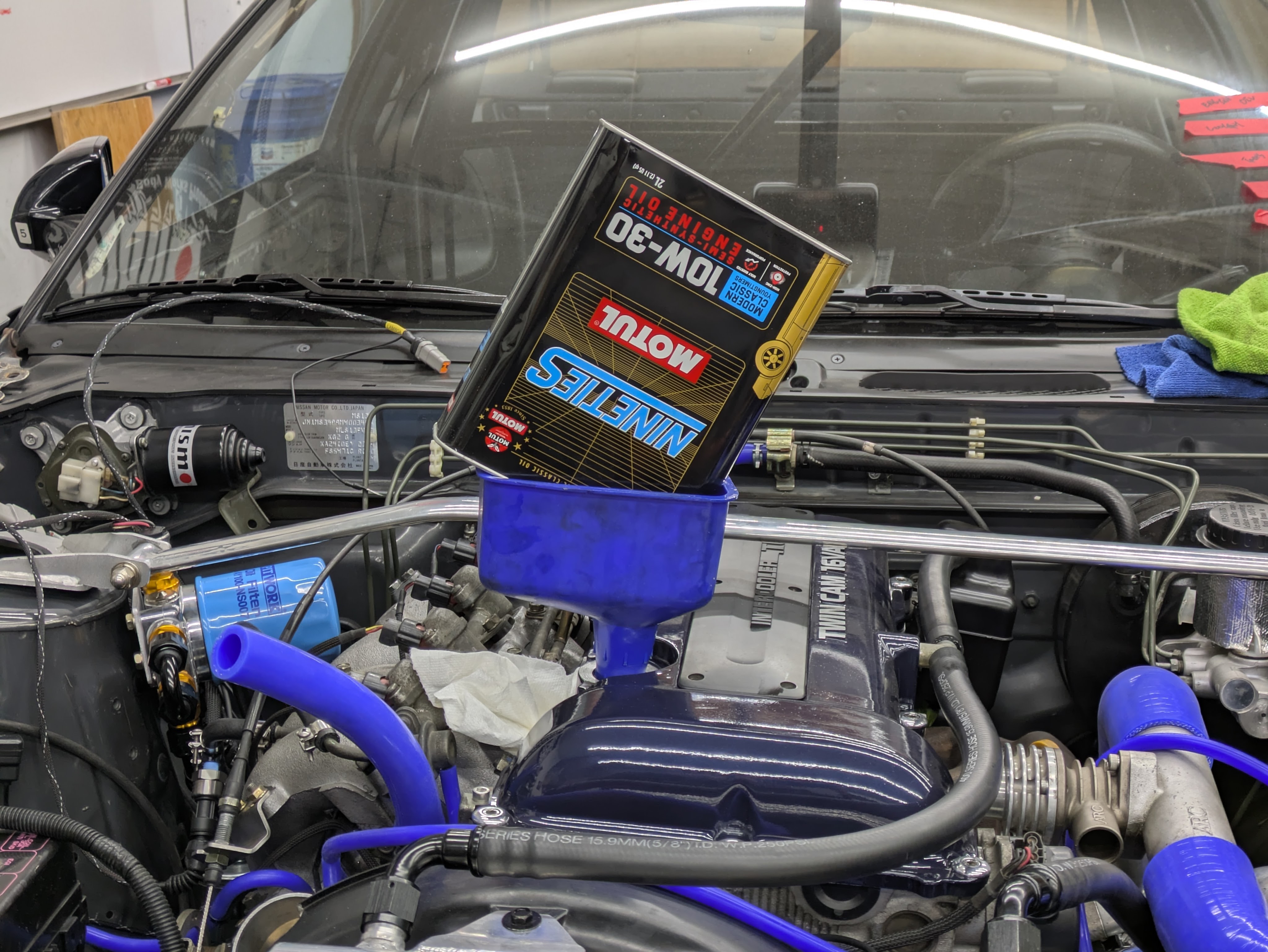
As all of the systems should be fluid tight, it was time to add fluids. Engine oil was first in the form of Motul Classic Nineties, which I originally bought a case of off of Turn14 because it was on sale, and a great oil for my Civic (I didn’t own the S13 at the time). I figured that even if it wasn’t the final oil I was going to have in the car (still undetermined), it was good enough for the shakedown and first event.
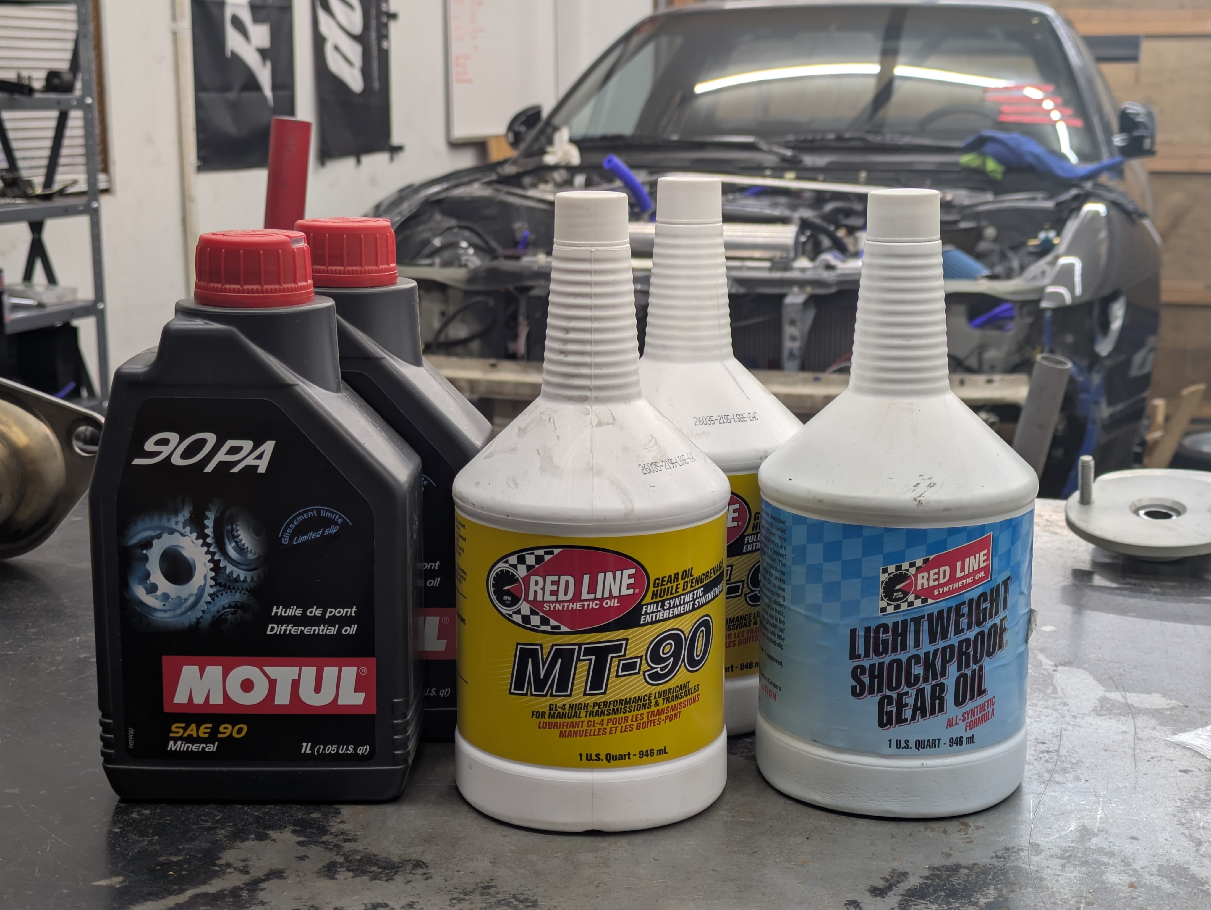
The transmission got the forum/friend recommended cocktail of Redline MT90 and Lightweight Shockproof. The Nismo 2 way, while having a Nismo branded fluid, was not available physically or worth the price. Motul PA90 was recommended from Touge Factory, and as a mineral oil advertised for clutch type LSDs, should do the job just fine. If it’s real clunky or chattery, I’ll splash in some Ford Friction Modifier, but this diff was silent before, which was lovely.
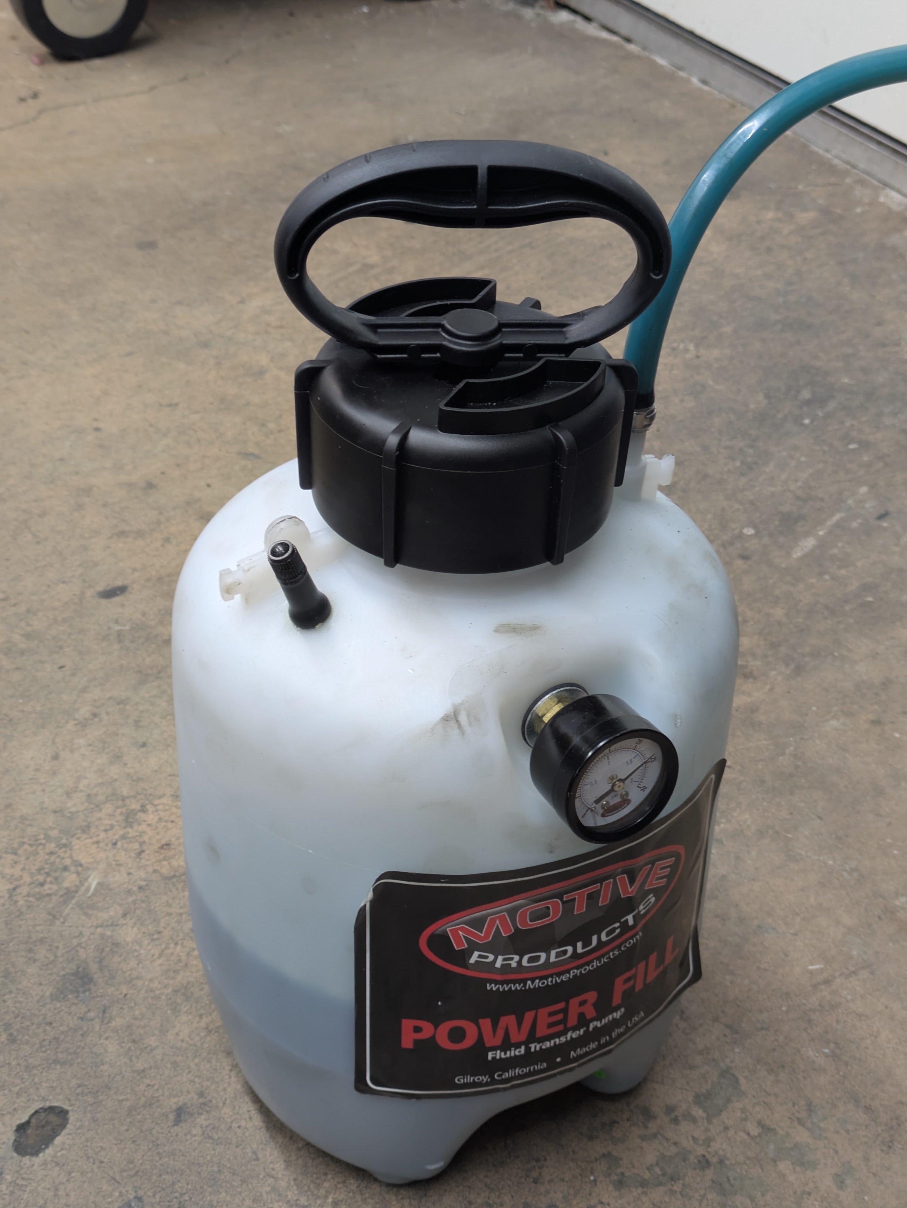
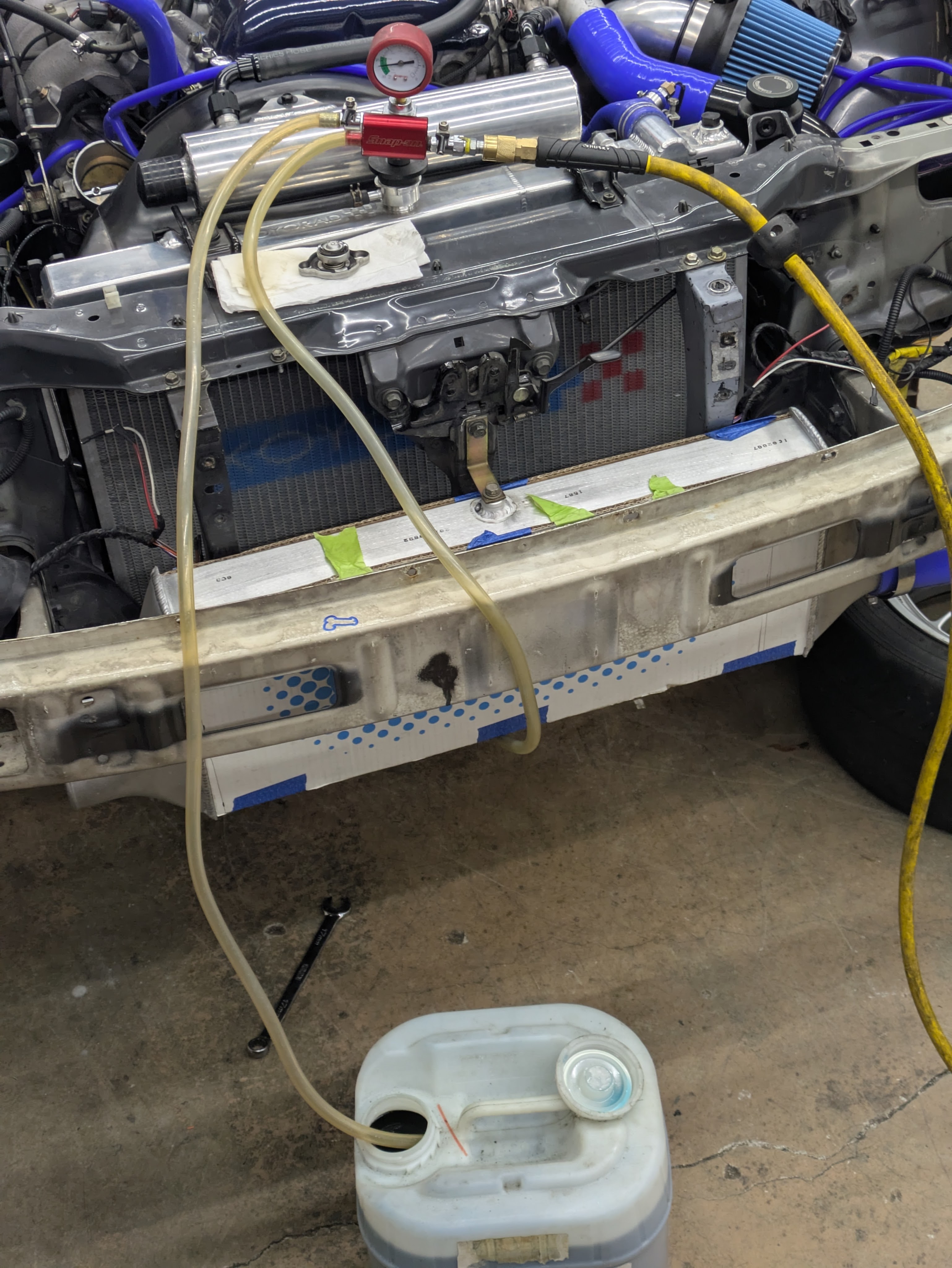
Coolant was next, and again, I was fortunate enough to have it on tap. I had acquired the dregs of many containers of Honda coolant that a good friend mixed together at a Honda dealer, and its the right color, so it went in the car. I didn’t document it, but after I assembled the heater core hoses, I pressure tested the system which did highlight two leaks. One was solved by a loose clamp under the intake (thank God I oriented them in a serviceable way) and the other was out of the upper radiator hose temperature sensor fitting, which never leaked previously, but easily resolved with some light cleaning and re-clamping. The system was then vacuum checked (which it passed) and vacuum filled. I will still check with the traditional style bucket bleed, but vacuum bleeding certainly is convenient, especially in a 100% dry system.
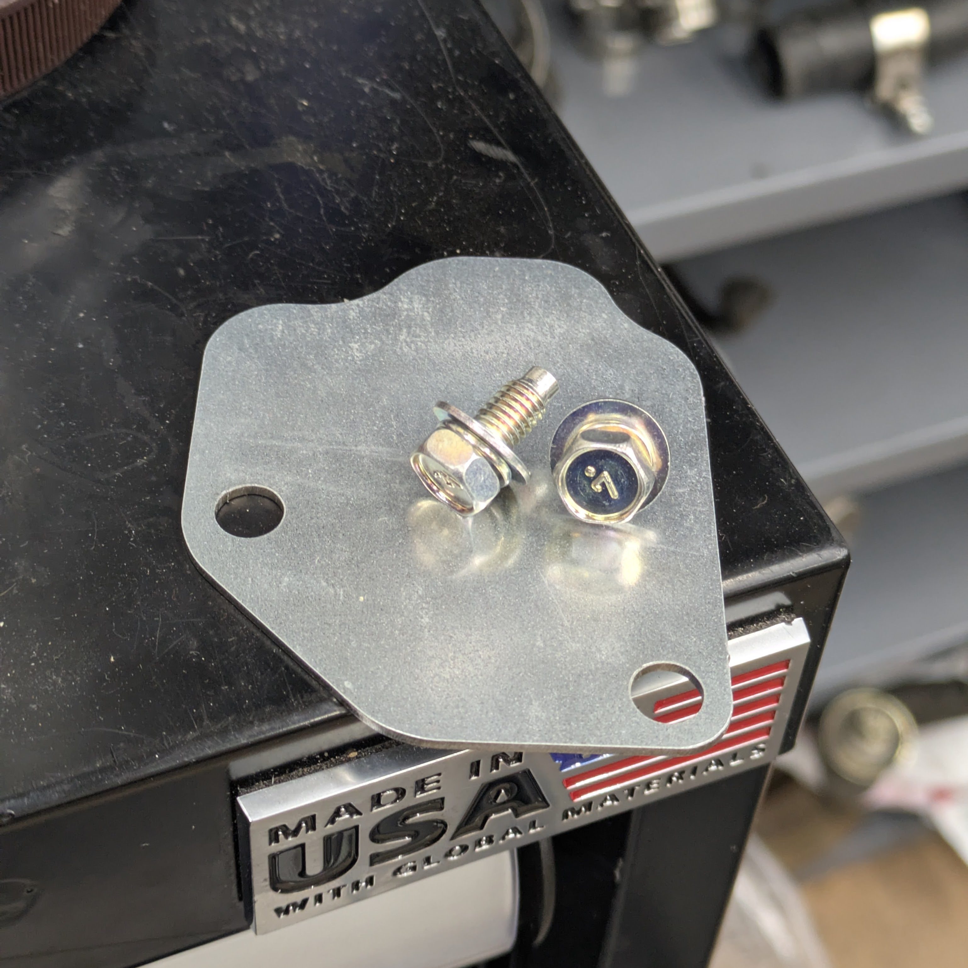
While I was filling the trans, I took a second to install the flywheel cover plate I had laser cut out of G90 galvinized steel. These are effectively discontinued from Nissan, and my last engine had one, and when it left I realized that Luis’s engine didn’t. Fortunately the new owner was cool and let me borrow it back to scan it and recreate it. While it doesnt have the rubber seal geomeometry around the edges, it’s as close as it can get, and as a plate designed to keep rocks out (or in the case of the automatic cars, access the torque converter bolts), it does it’s job just fine.
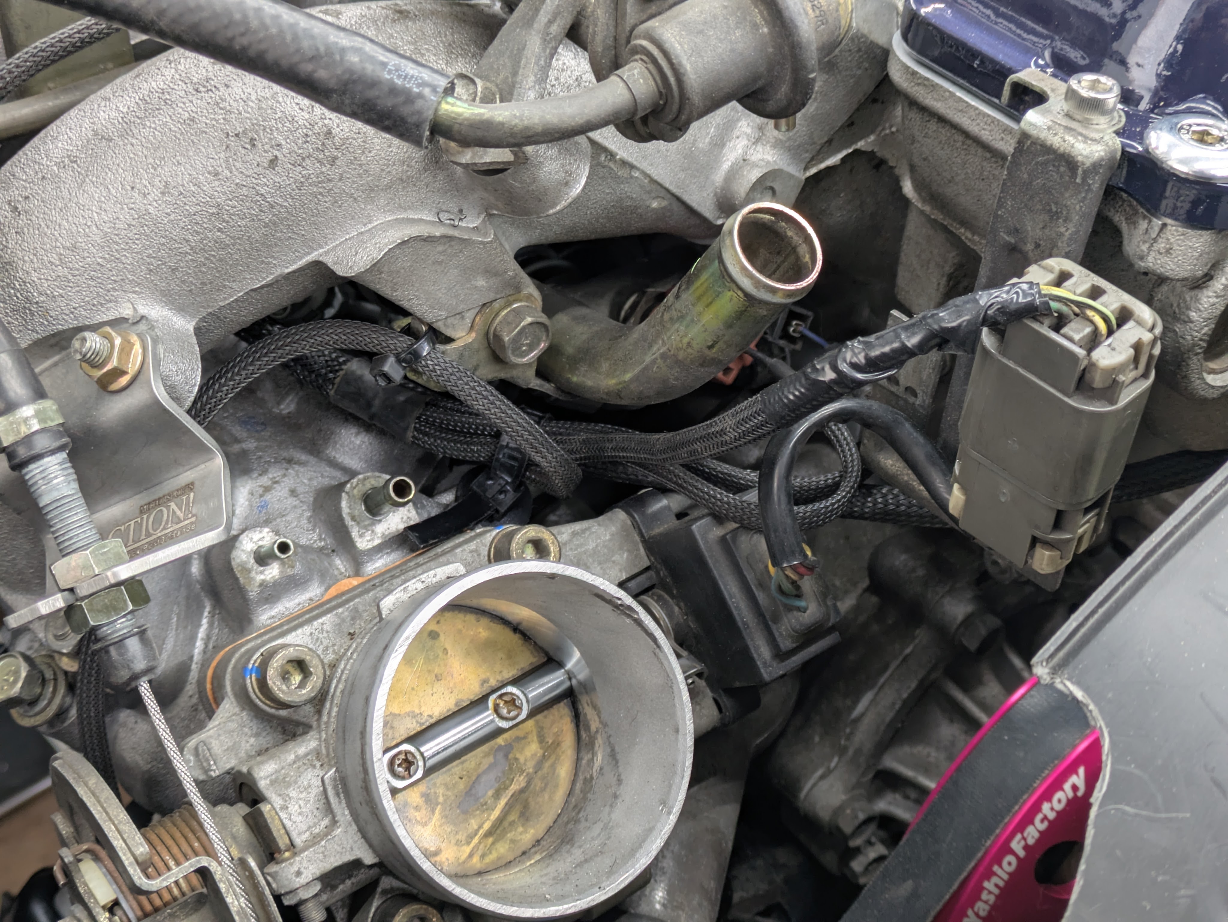
As final assembly was looming, I needed to tie up a few (ugly) loose ends. Off camera, I had Ethan weld in a 3/8NPT bung for the IAT sensor into the intercooler pipe near the throttle, so the finish was noticeably removed in that area.
My intercooler pipes are an HKS kit from the early 2000s. It reused the factory SMIC inlet pipe and bypass valve pipe, while adding a lower connection to the FMIC. Weirdly enough, the outlet pipe off the intercooler is cast aluminum, I believe to achieve a tighter radius, so it’s kind of weird all over. Or at least versus modern counterparts.
Either way, these pipes had shown their age over the years, so I spent the time to strip the old powdercoat off and paint them.
This is my new favorite rattle can paint, hands down. What you see is Seymore MRO in Stainless Steel. This stuff has been around for a while but this was my first time using it. I originally saw it on Stanceworks many years ago, and I knew it was the color tone that I wanted. It lays super, blends great if you need to touch it up, and they have a wide pallet of colors. Highly recommended, even over products like Steel-it if you don’t need the welding properties.
Now if you’ll indulge me, we must take a side quest to talk about the other important pipes on the car.
This car, over the course of my ownership, has had 5 exhausts. While absurd for the approximately 2000 miles I drove it before tearing it apart, let me elaborate.
The car came to me with a Buddy Club Circuit II on it, which is effectively a straight pipe with a brand on it. Single exit cat back, 3″ all the way through, and a tiny excuse of a resonator hidden in the midsection. While it sounded righteous, especially with the old HKS tubular manifold, it was far too loud for dual duty ambitions. I made a fairly conscious decision to not try to pursue custom exhausts on this car since there are so many options, so modifying it was out, nor did I want to cut up an exhaust that someone probably wanted as-is.
Shortly after purchasing it, an HKS Hi-Power made it’s way on to the car. This was entire due to cost and noise reduction. I knew it would fit and sound a lot more reasonable, so I snagged one. It sounded great, and hung exactly as low as everyone says they do. I literally dragged it on the transition out of my parent’s garage when I put it on. I intentionally let that exhaust go when I sold my SR swap to sweeten the deal for the buyer, knowing that it was going to have to be modified to remain on my car, but once again, no custom.
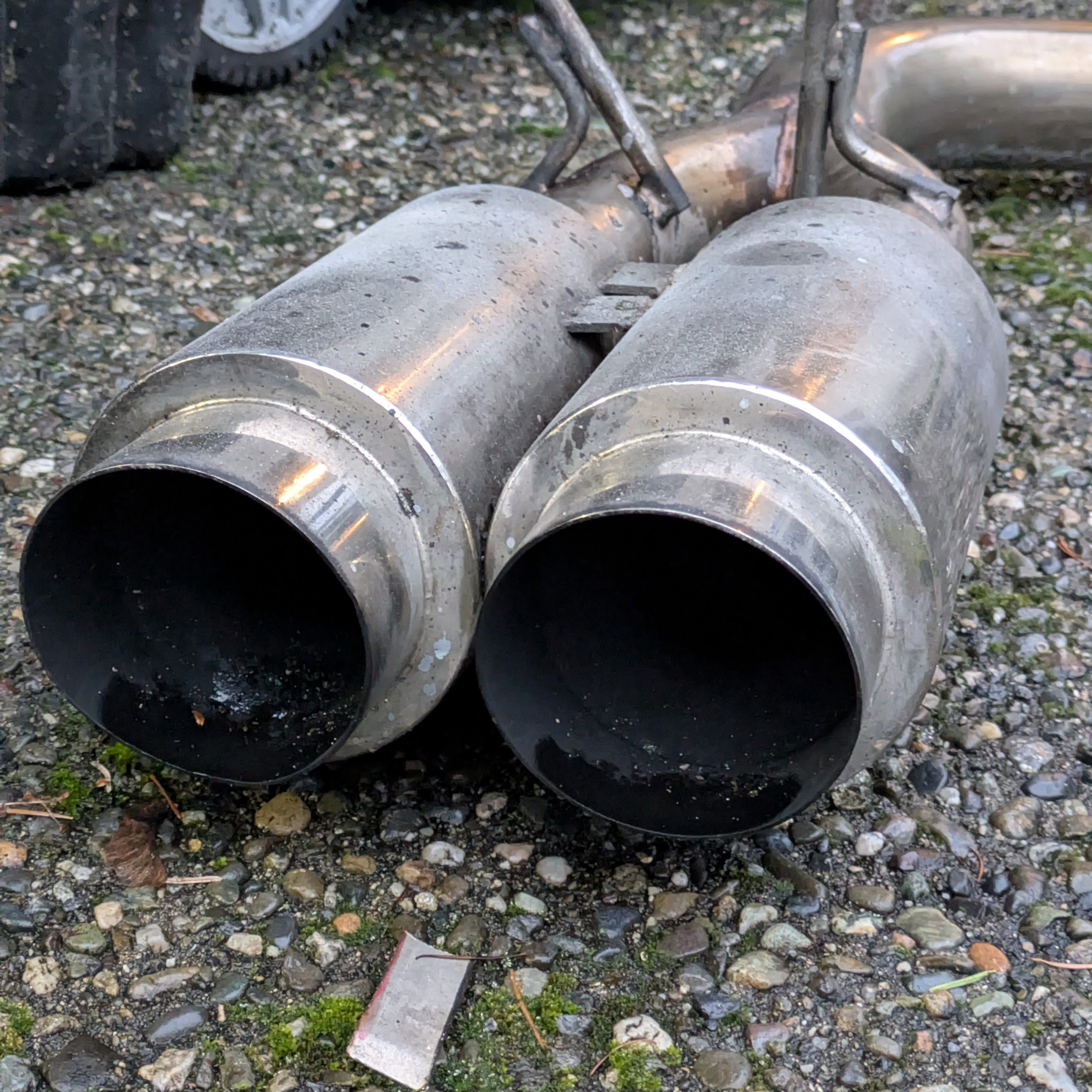
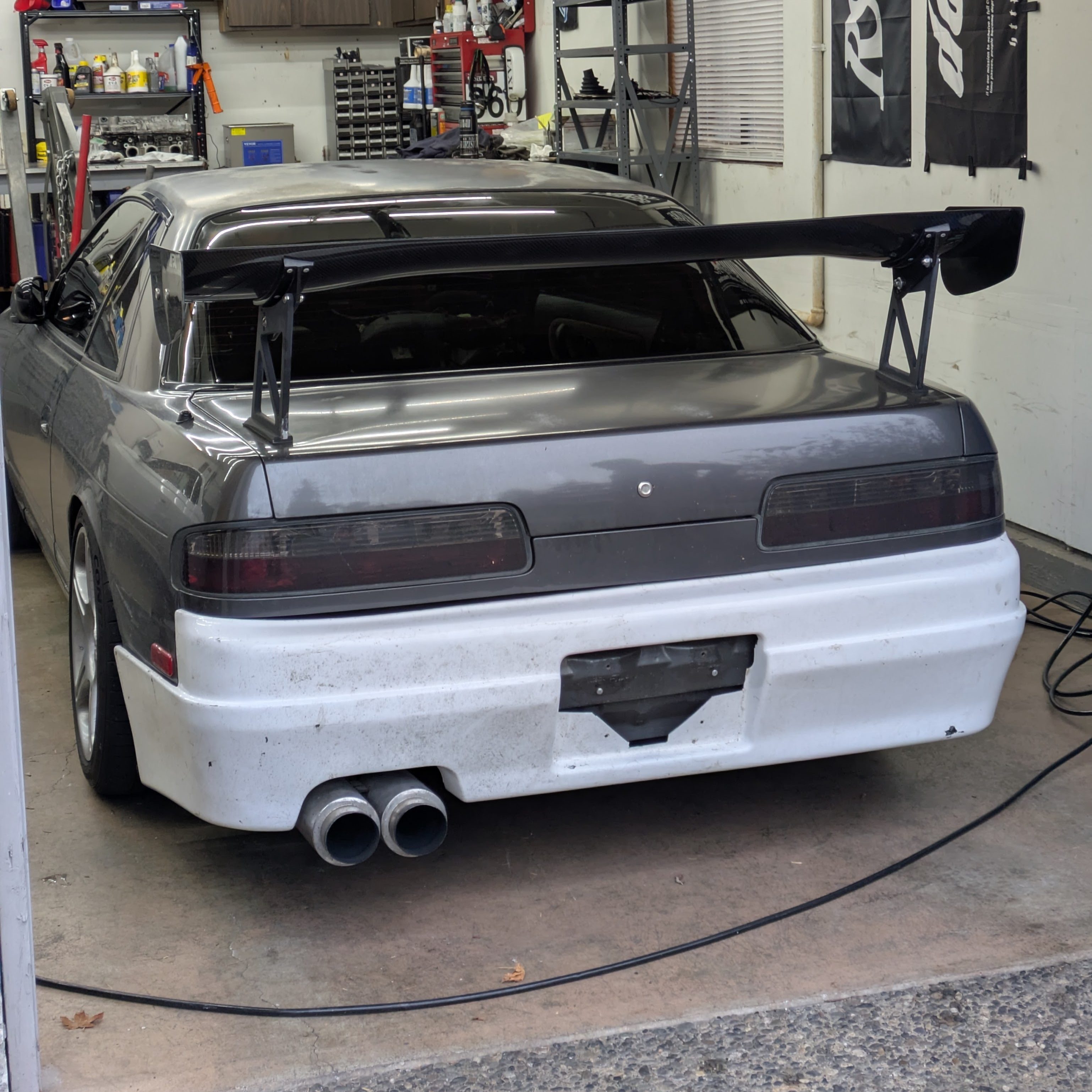
During the “car runs and drives” period, I spotted an RYO twin cannon on marketplace and promptly picked it up. I figured this would be one of the only exhausts that would actually fill out the gargantuan hole in the Instant Gentleman rear bumper, and I threw it on before I pulled my motor to check fitment. Unfortunately, it was not only ugly, but it fit poorly. It would need modification to not hit the trans tunnel, the tips need to be pulled in, and it was too loud for my taste, so a muffler would have to be spliced. Sold it.
With my options slimming considerably, I looked around for what I could get new, that would fill the bumper out, and wouldn’t be too loud. The PBM oval exhaust almost made its way on to the car for ground clearance and tip presence, but it would have been incredibly loud as it has no mufflers. The only solid twin tip at that point was the ISR MB SE twin tip, which sounded good on a few videos and looked right, but I just thought about my social credit score plummeting at the realization that I had an ISR part on my car. No shots at them, they make a product to a price point, but after so much adherence to an era, it would feel like a modern copout. I wasn’t stoked, but I bought it anyway. It never made it out of the packaging. Sold it too.
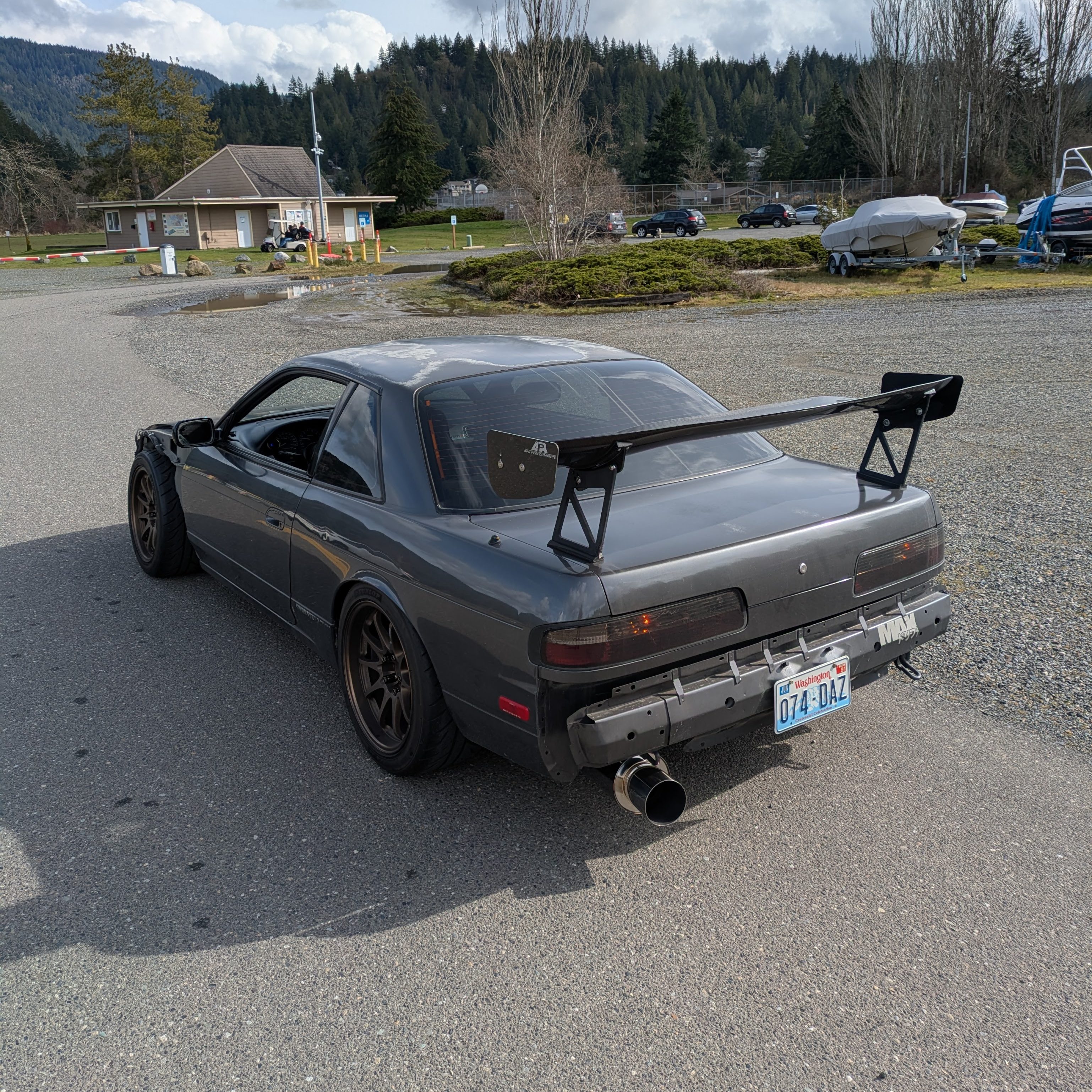
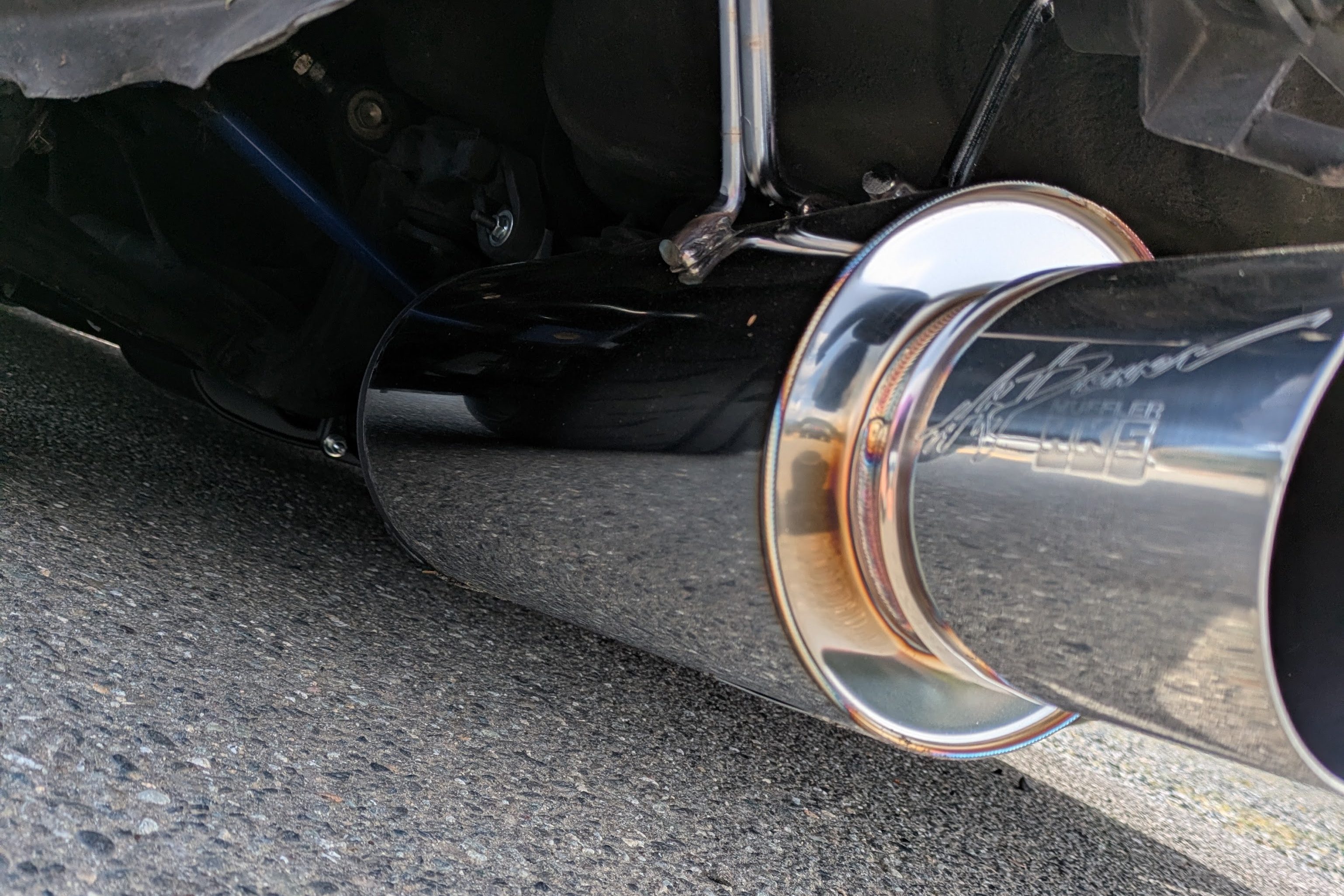
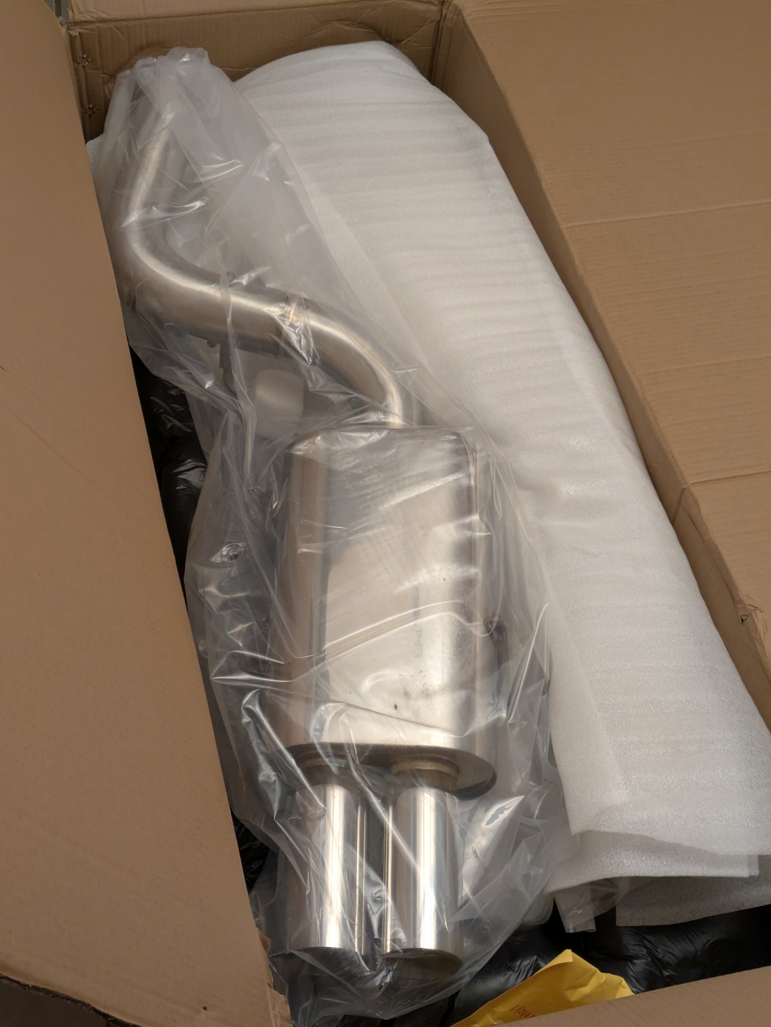
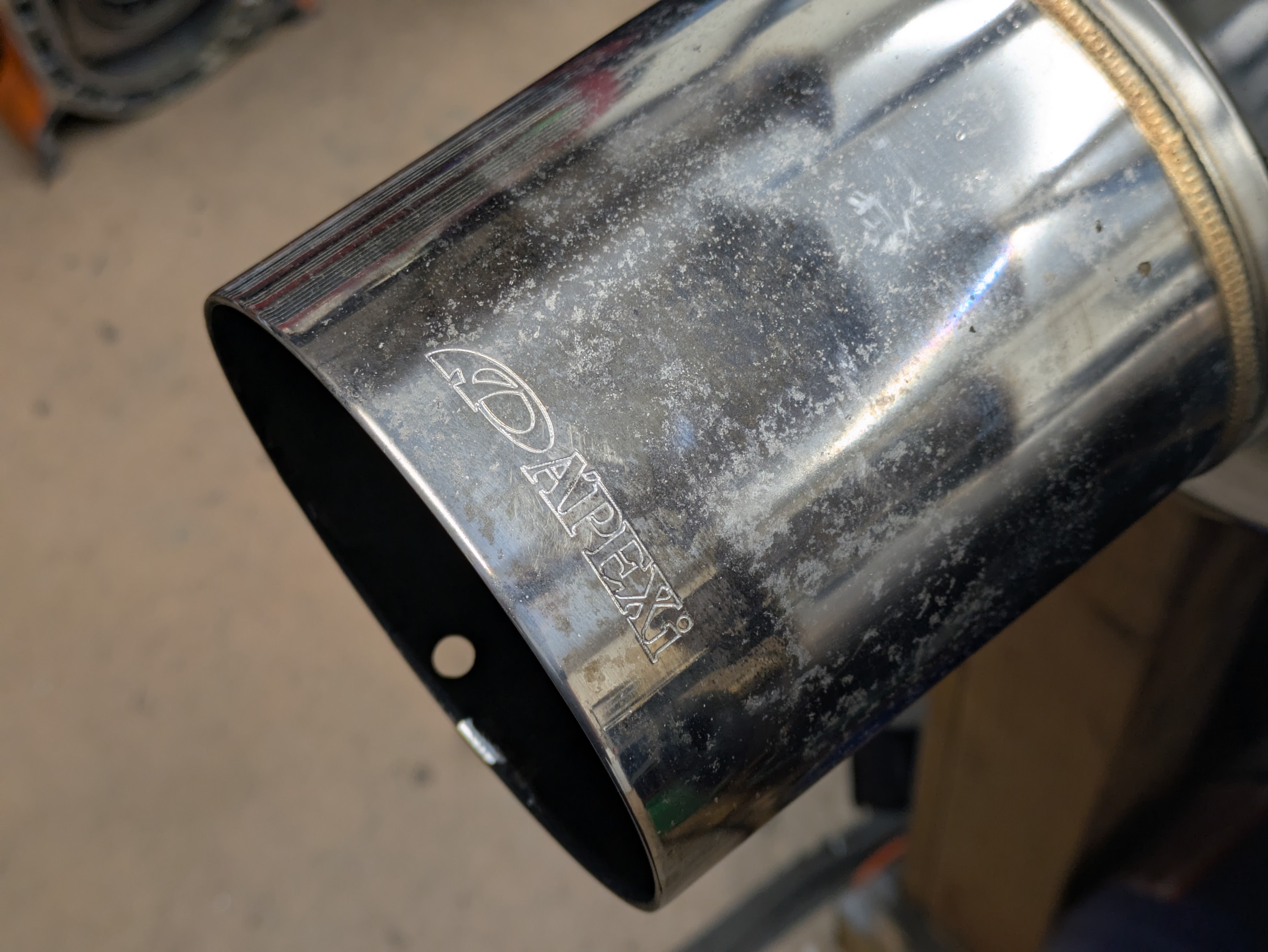
For whatever reason, probably cosmic ripples in the universe, Alex texted me about 3 days after I received my sadness in a box (ISR) to inform me that he retail-therapied himself a new exhaust and I could buy his Apexi GT Spec catback. I was already considering the return costs of this ISR, and this was the perfect exhaust for the era and style of my car. He threw a price out, I didn’t argue, and I had exactly what I was after. I really like the look of a cannon in the rear section of this bumper for whatever reason, and GT spec is arguably one of the best sounding exhausts for an SR, so I was stoked.
My father was kind enough to make a 1 day drive south to go get it, as I knew that I really didn’t want to delay starting my car just for the exhaust. He was able to maximize the beautiful day for a roadtrip by also acquiring motorcycle parts for the sister’s boyfriend, and Tesla juice is cheap, so everyone won.
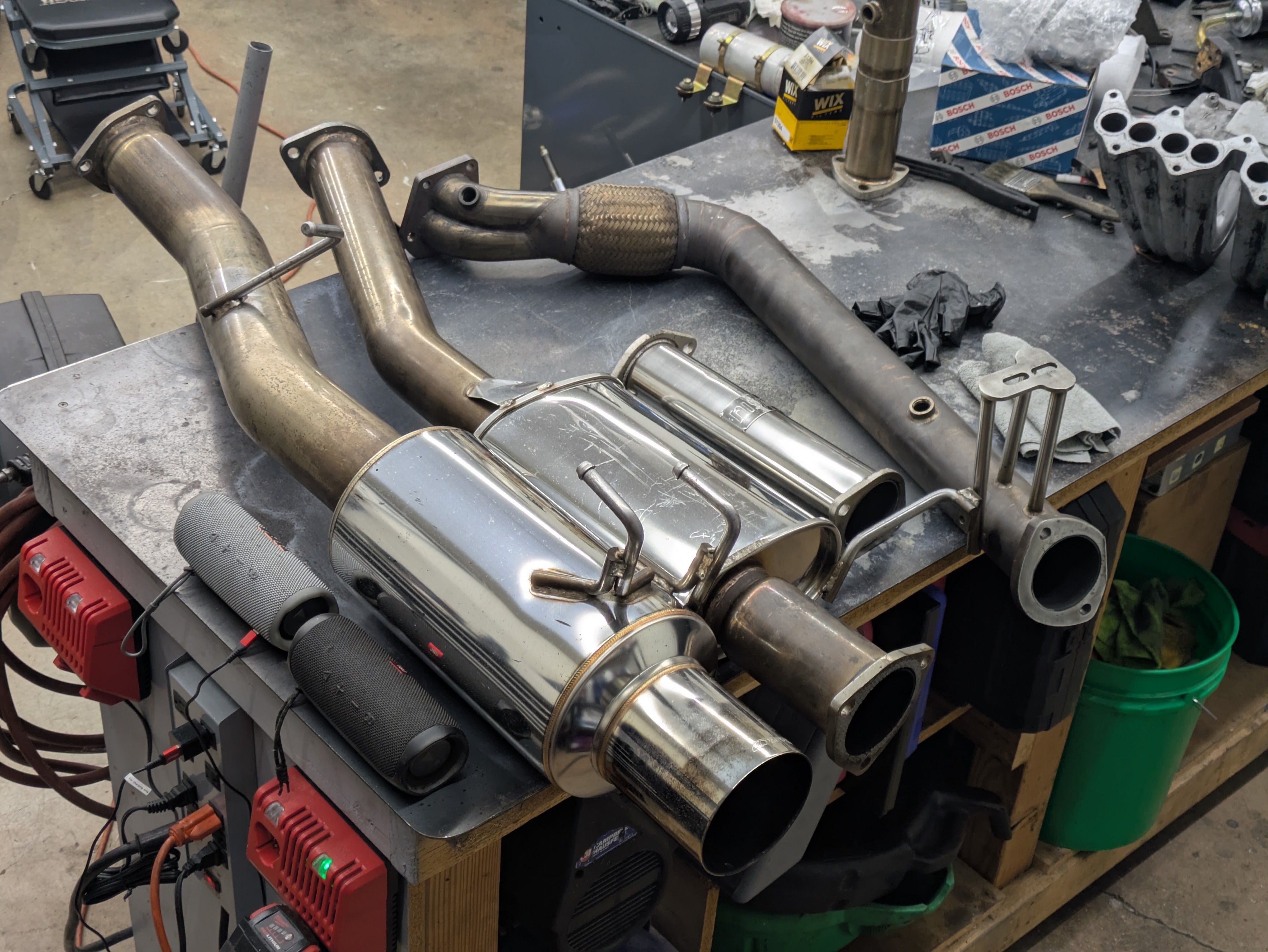
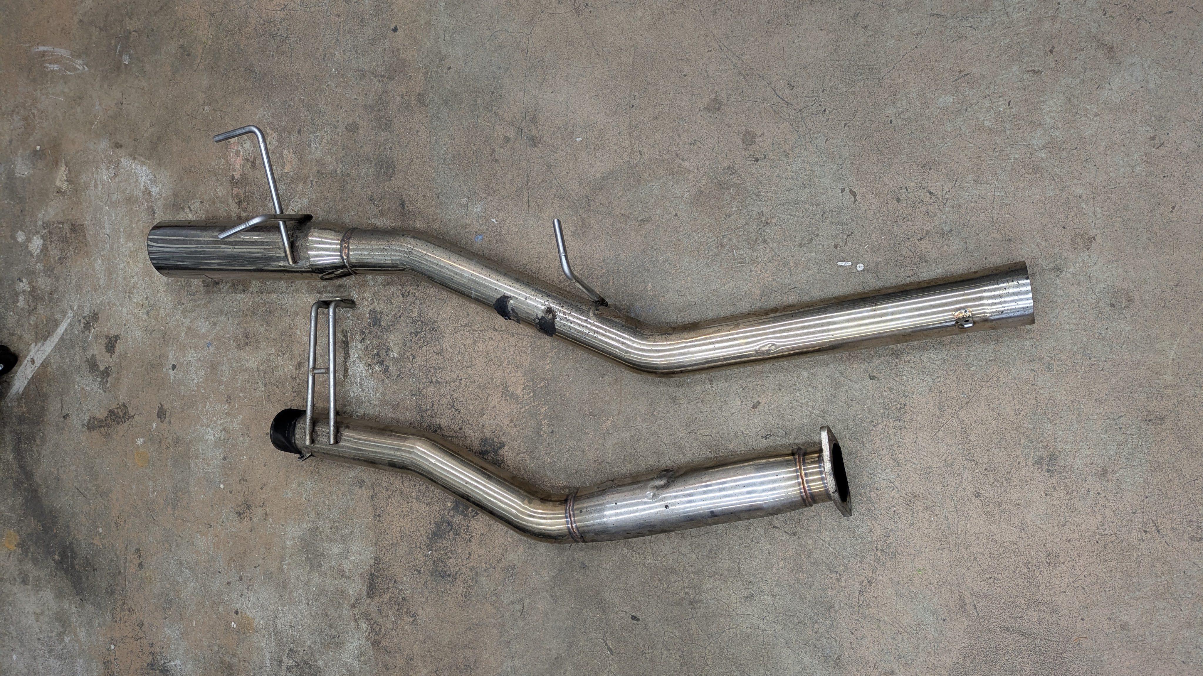
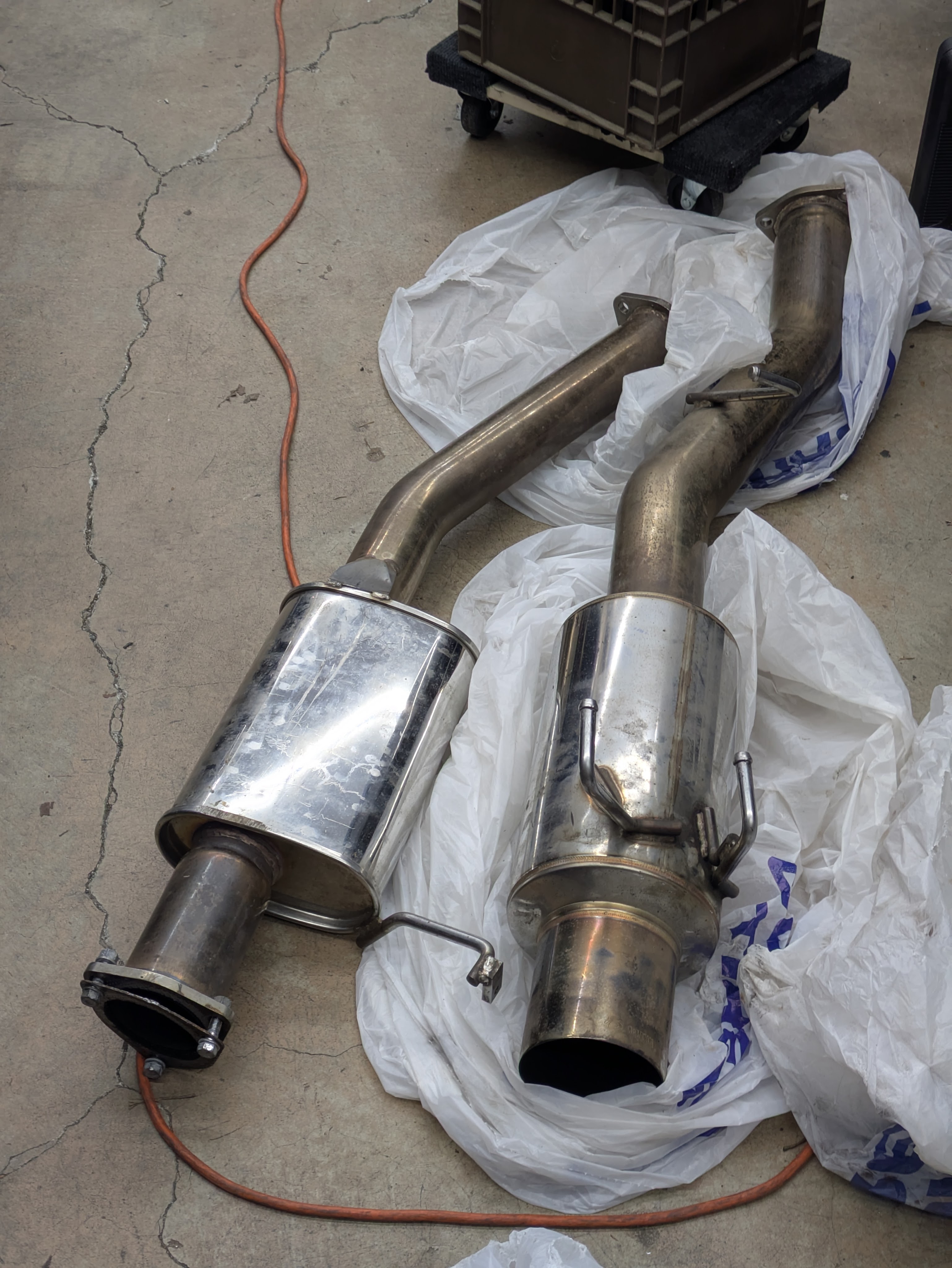
I promptly cleaned it up with some Ospho (primary ingredient phosphoric acid) and some #0000 steel wool. This combination practically melts surface contamination off of stainless with zero effort, and the results were excellent. This exhaust is 10 years old and has been on a track car that whole time, but it held up shockingly well all things considered. I found one crack near a hanger point, but luckily welder friends are nearby, so I was able to drop it off to another welder friend Aaron to get it welded. (Ethan was out of town. Not cheating on my boy like that)

The test pipe in the photo bears noting. I gave my old test pipe away with the last exhaust, not thinking much of an innocuous pipe with two 2 bolt flanges on it. What I was about to discover when I went to replace it is that the EPA pretty much whacked test pipes off the face of the Earth (eBay). The only way to buy one was to get it straight from the motherland, and I didn’t have RHD Japan/Nengun timelines. I put out a WTB on Marketplace for one, and fortunately someone wanted to trade a test pipe for all of my power seatbelt stuff that I had posted a few weeks prior. A quick evening trip to South Seattle netted me a very fake but functional test pipe. I flattened the flanges with a way stone and used the same external restoration process on it as I had the exhaust, and it turned out quite nice considering.
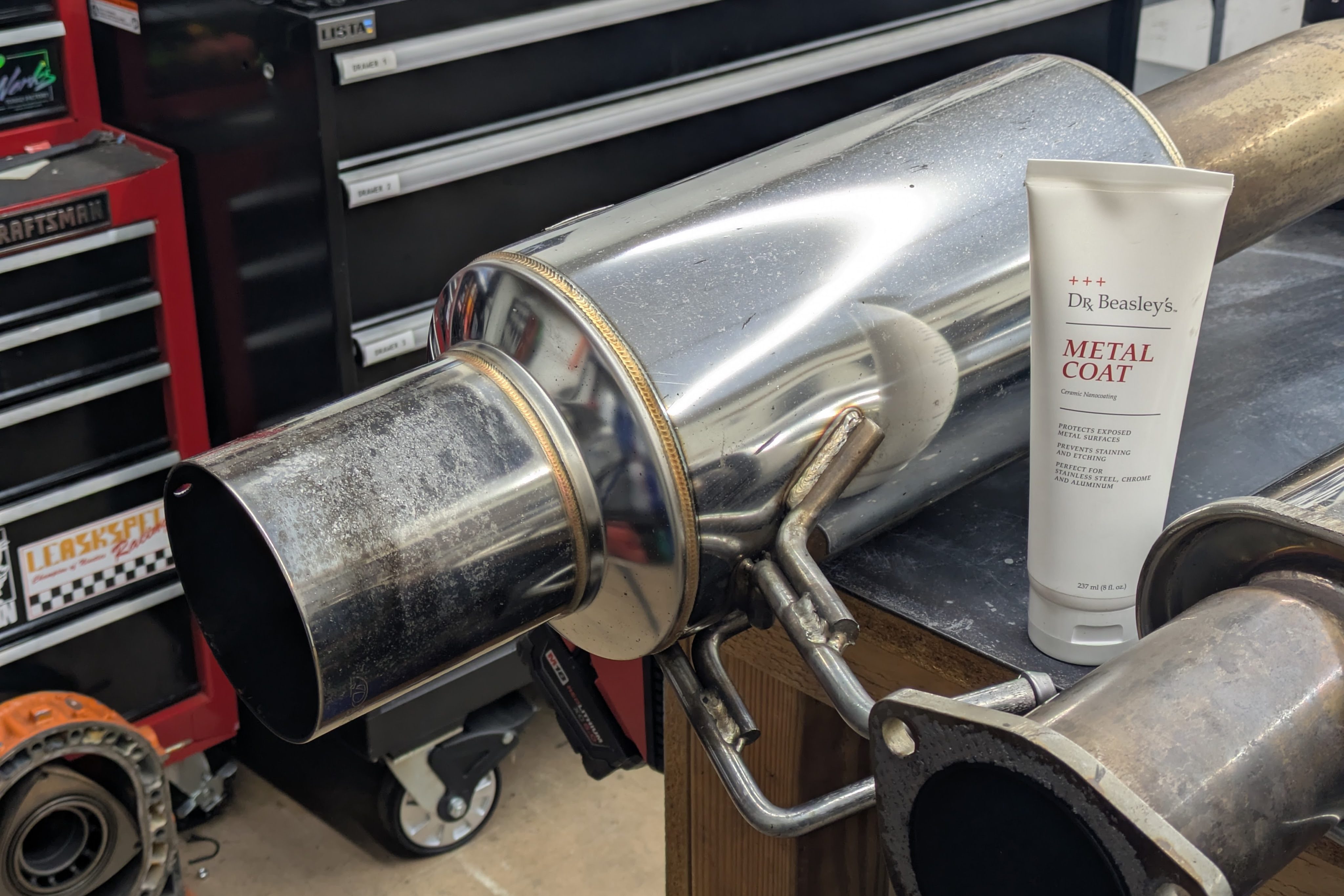
I finished it off with a coating of Dr. Beasley’s Metal Coat, which is as close to a ceramic coating for metal as you can get. It keeps the metal nicer for longer and its cheap and easy to apply, so I throw it on whenever I can. It’s temperature resistance is exactly why it’s on the valve cover in hopes to keep that aluminum nice.
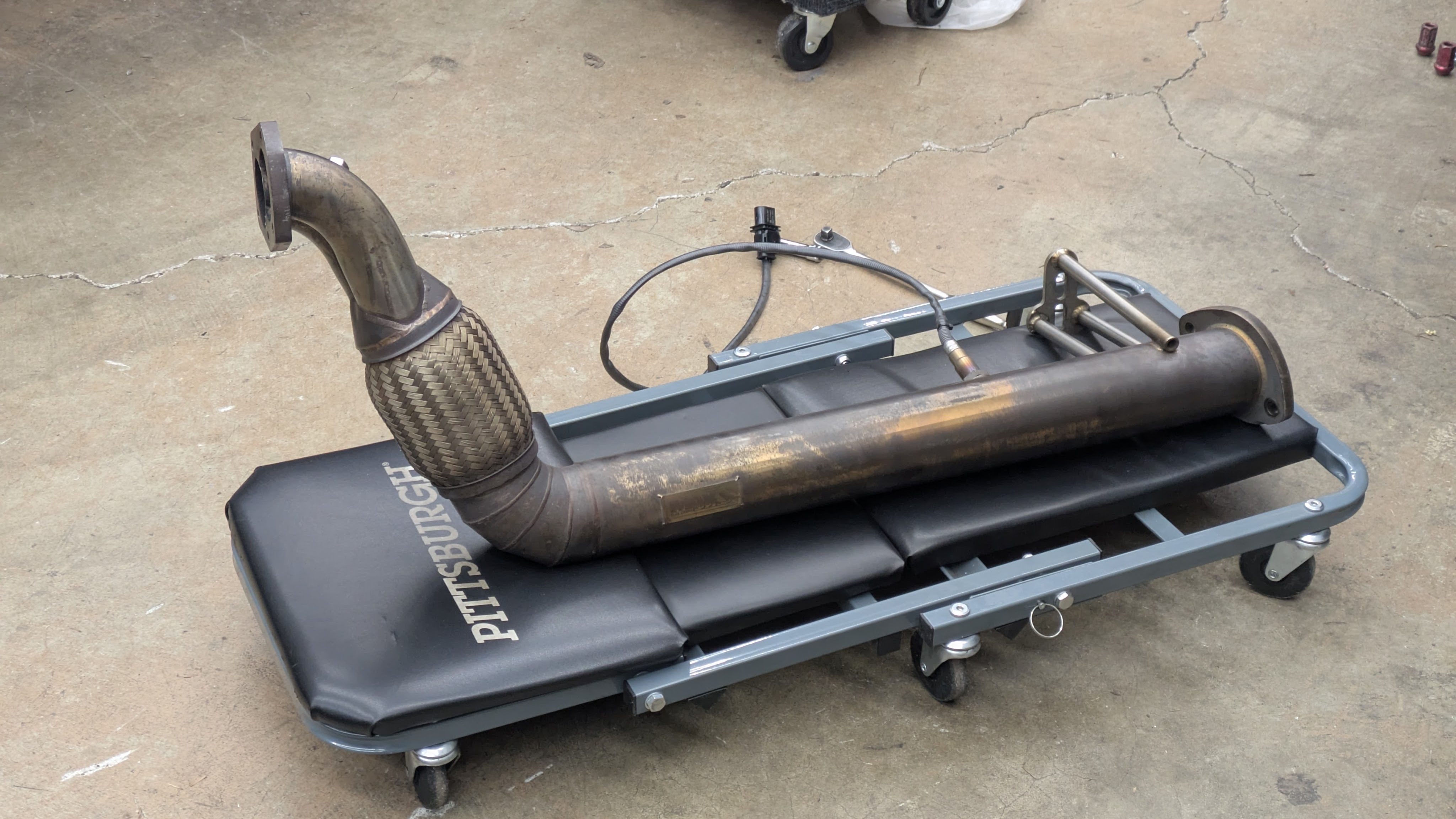
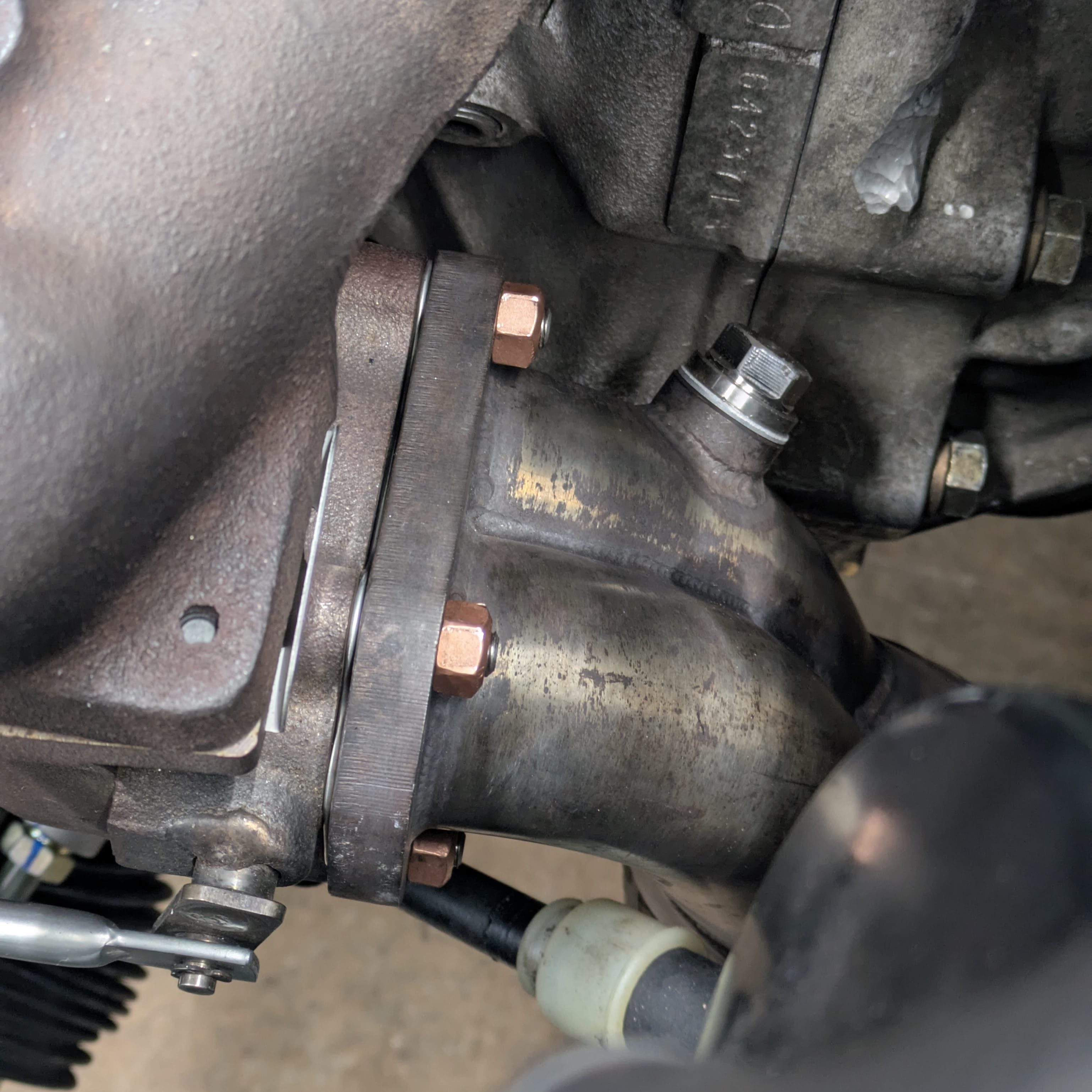
The exhaust installation starts with my old PBM Cobra pipe. I got Luis’s in the engine deal, but I knew mine fit great and it was custom tuned (read: dented) for additional ground clearance. I went to install it and immediately ran into a fitment issue, as the divider flange ran straight into the divider flange on the turbo exhaust housing. This revealed that my last turbo was not in fact an S15 ball bearing T28, it was a journal bearing S14 T28.
I pulled it back out and chopped it off, and then it fit great. I also had to take two of the stamped retaining rings off of my OEM S15 exhaust gasket because of the JWT stud kit, but that was easily resolved.
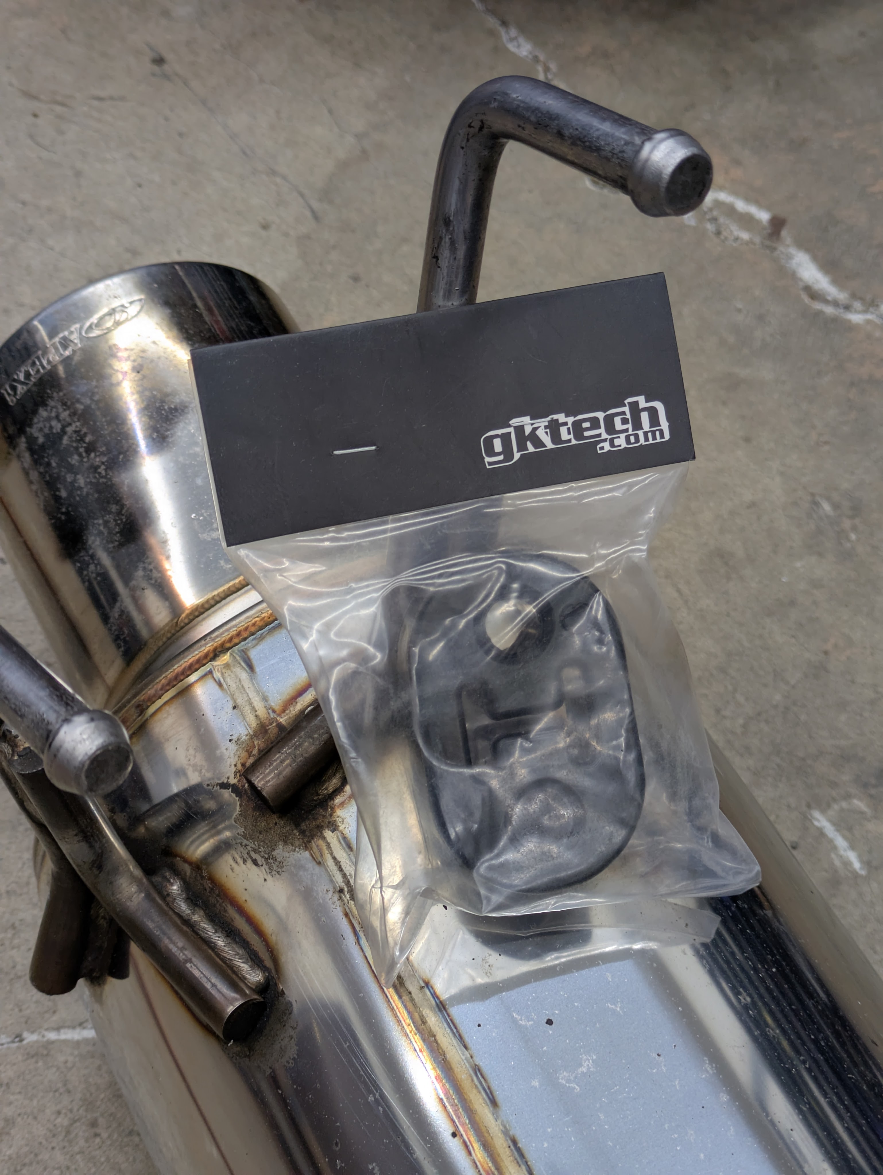
With that off, I moved on to the rest of the exhaust. I have been a massive fan of OEM dimension polyurathane hangers ever since I had them on my RX-8, so I grabbed some GKTech ones when I ordered my ISR exhaust.
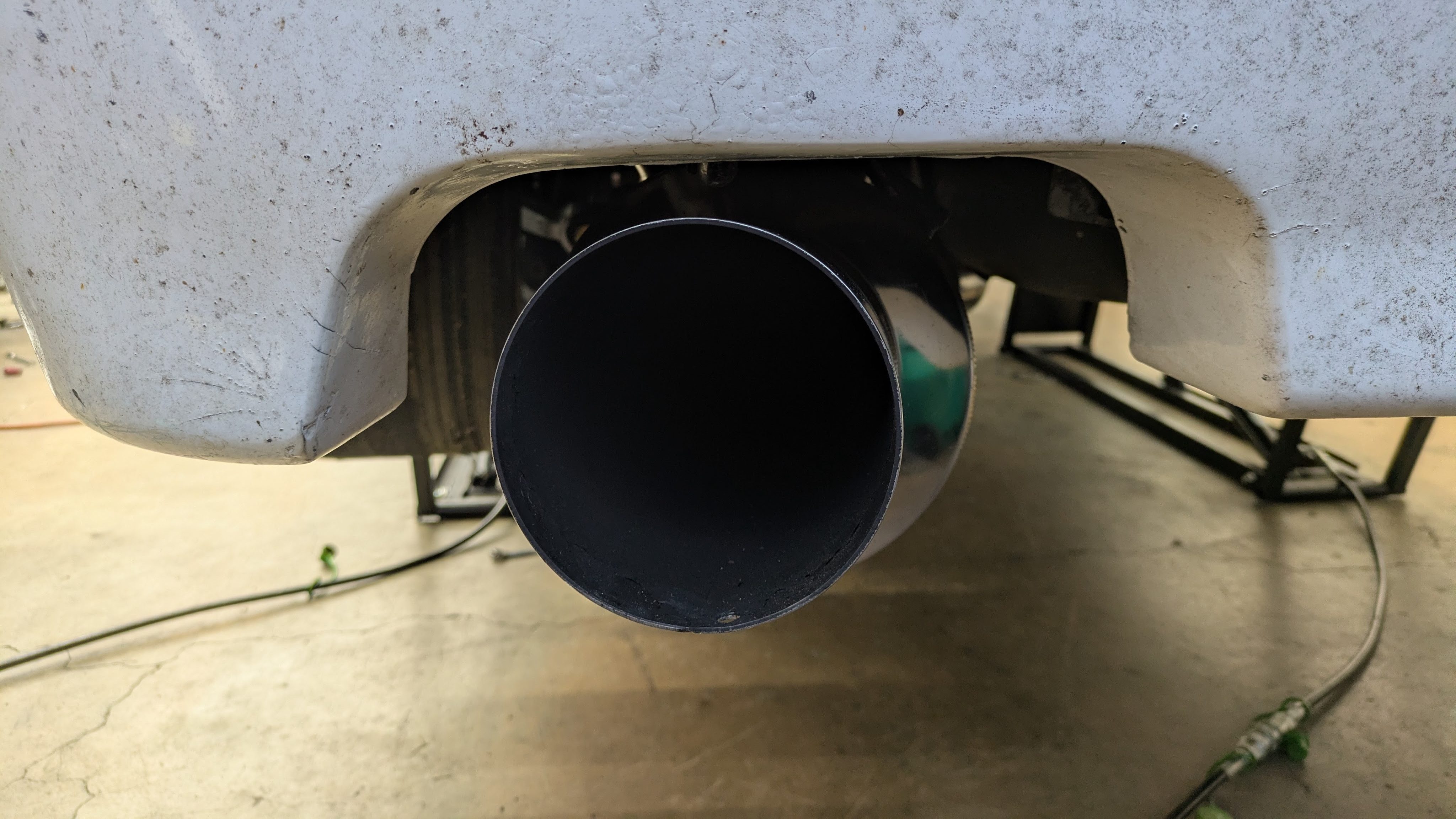
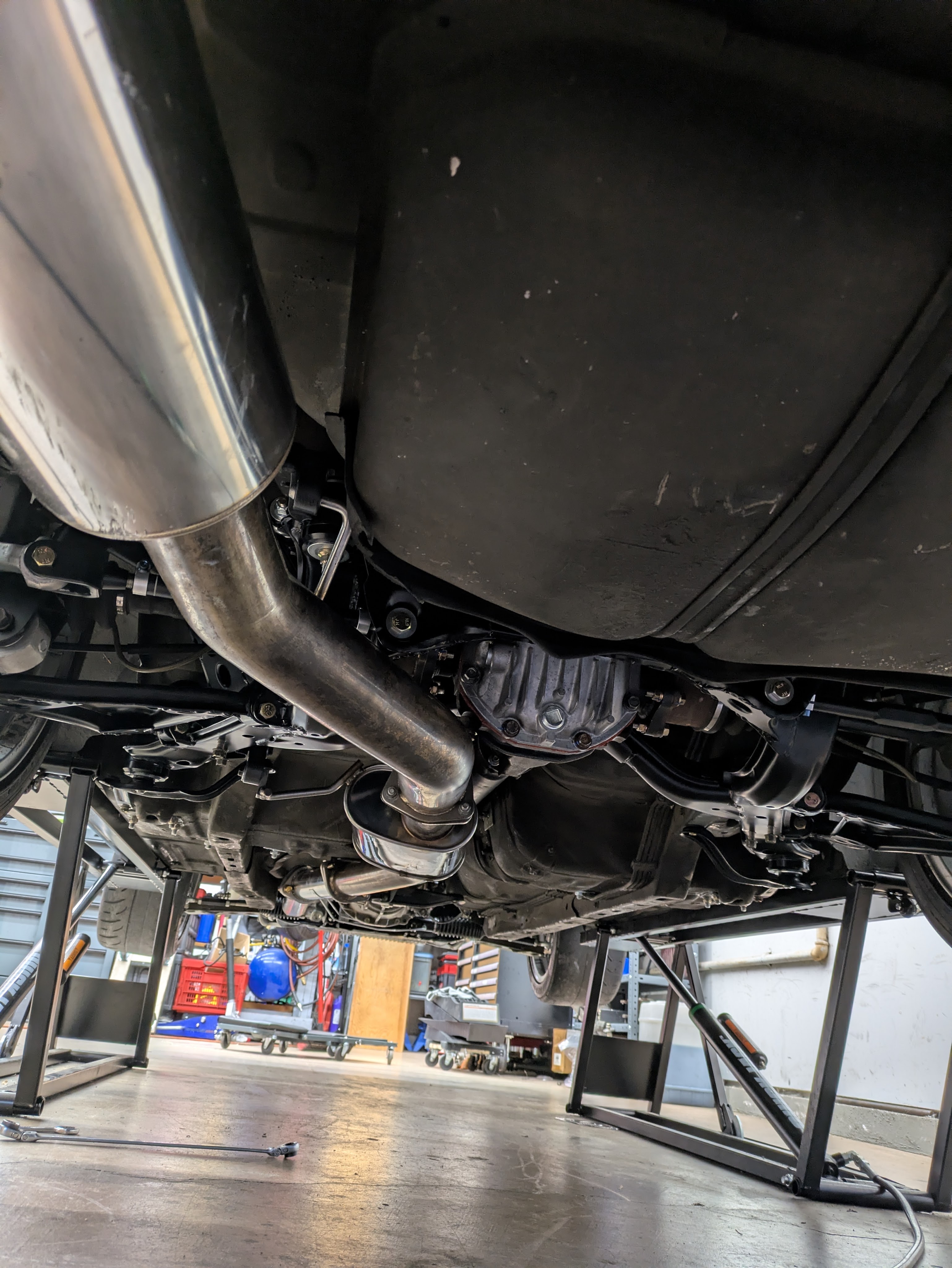
Surprise surprise: Apexi fitment was magical. Everything lined up perfectly, all the hanger locations were perfect. Dead easy exhaust install. Unfortunately, I had a confluence of factors that caused the test pipe to be quite unhappy. The 15mm rear subframe raise also raised the two exhaust pickup points on the catback, and with the rigidity of the poly hangers and the my desire to have it tucked as high as I could get away with, The test pipe flanges both leaked regardless of how hard I tightened them (spoiler, I knew they leaked when I started the car). I has already tightened the bolts past the point of comfort, and I am praying I didn’t warp the Apexi or PBM flanges doing so, so I threw in the towel and ordered materials to have a test pipe custom fabricated. I’ll take a custom test pipe if everything else fits great.
(Thomas from the future again: I did get a test pipe fabricated. The flange on the Apexi was bad, so that was replaced as well. Now the fitment is perfect and it has no leaks. Thanks again to Ethan for getting that knocked out.)
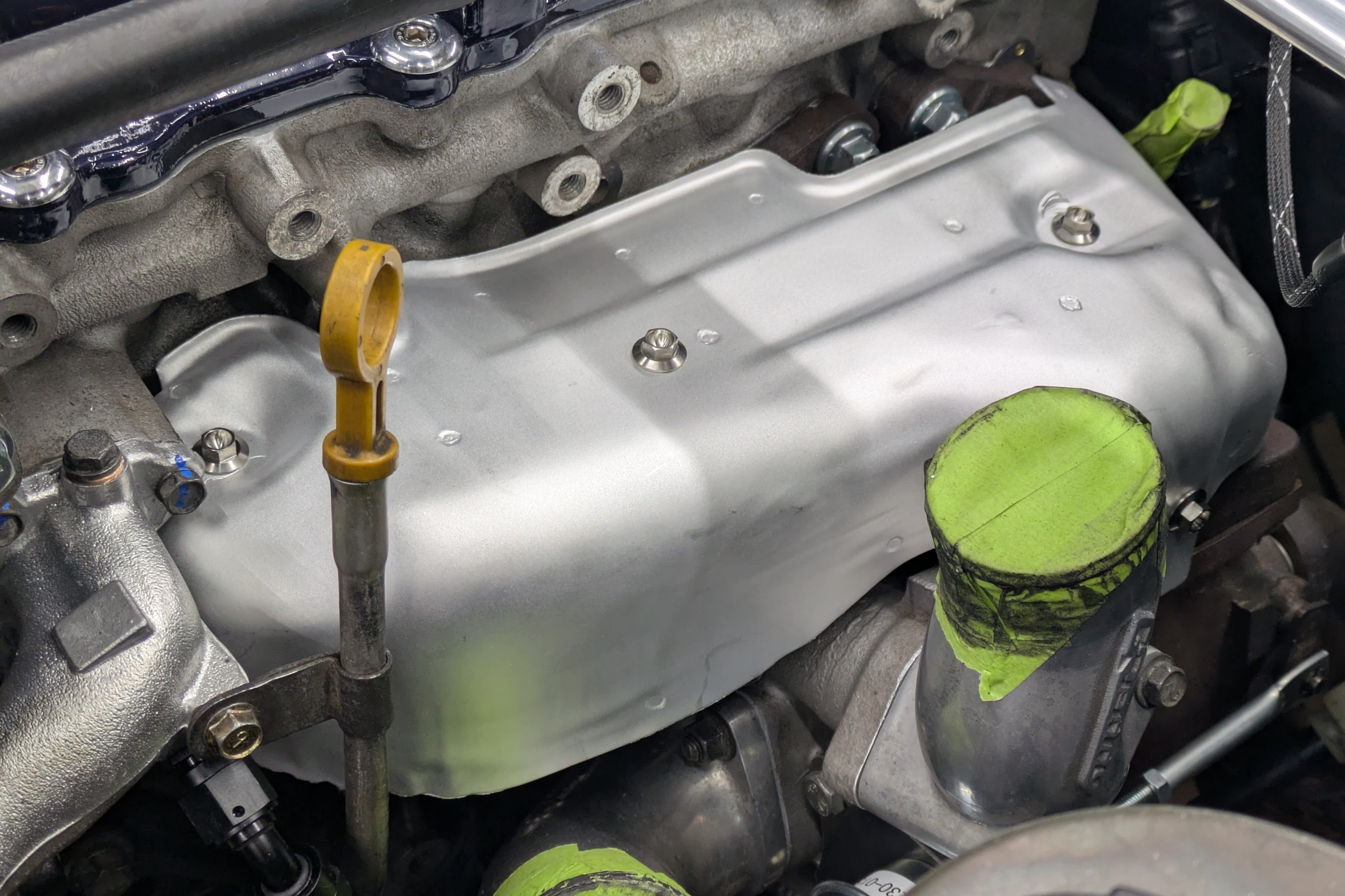
Once the exhaust was on, I was able to install all of the heat shields and PCV system for the final time.
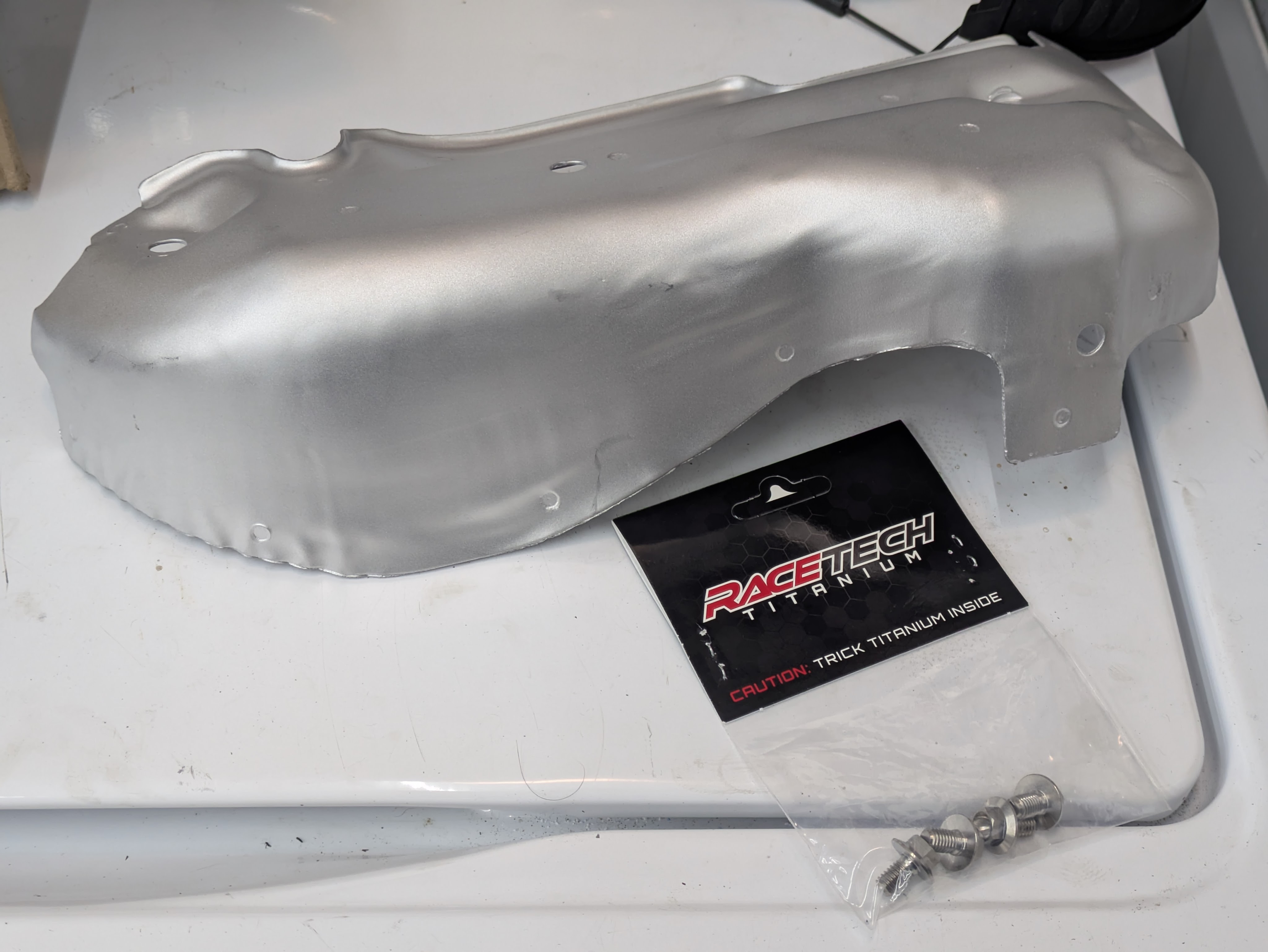
The heat shield itself is already very extra. I took a stock heat shield and sent it off for Jet Hot Coating to make it as effective as possible at keeping engine bay temps down. I have considered doing the manifold, turbo back housing, and downpipe, but we’ll see if that is worth the investment as the car gets tested. The heat shield was more of an aesthetic decision as it dominates so much of that side of the bay. I didn’t want high heat spray paint to just chip off, so this was the way to go.
To go along with my fancy heat shield, I was unsatisfied with the OEM zinc coated bolts to attach it, as they will immediately corrode when the zinc tarnishes from the heat of the exhaust. The only way to keep it nice was titanium, and so titanium it got. These came from Race-Spec, and although I am usually a Pro-Bolt guy, these had a much larger integrated flange was able to accommodate the damage that the heat shield bolt holes sustained from time and age.
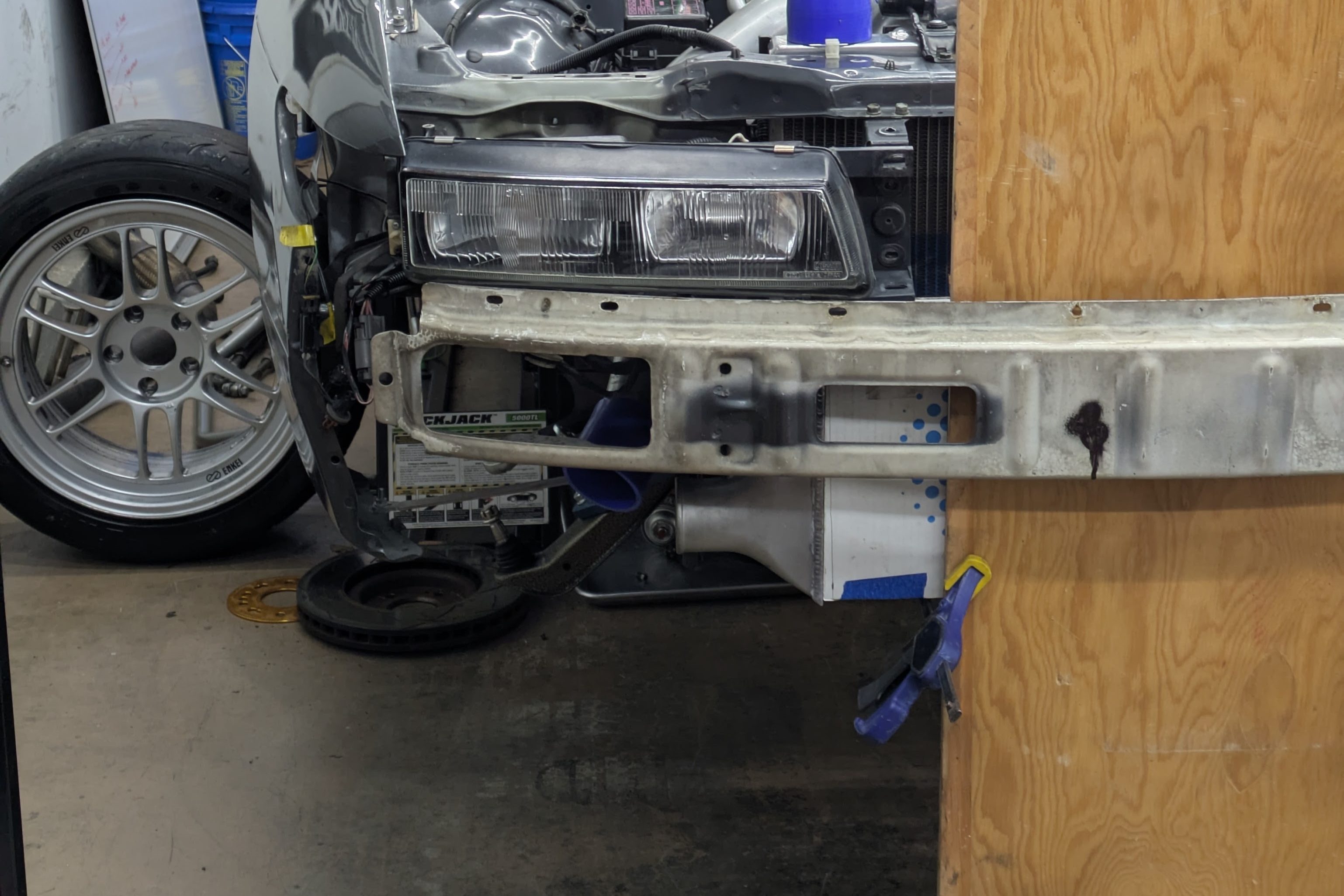
I stated earlier that the intercooler piping fit perfectly with the addition of new couplers and some slight tweaking. While true, there was a need to expand the drivers side apron hole as the new coupler was much larger in diameter than the old one. This was all made up for in wall thickness, which is a welcome addition, but the new coupler was a press fit in the old 2.5″ hole.
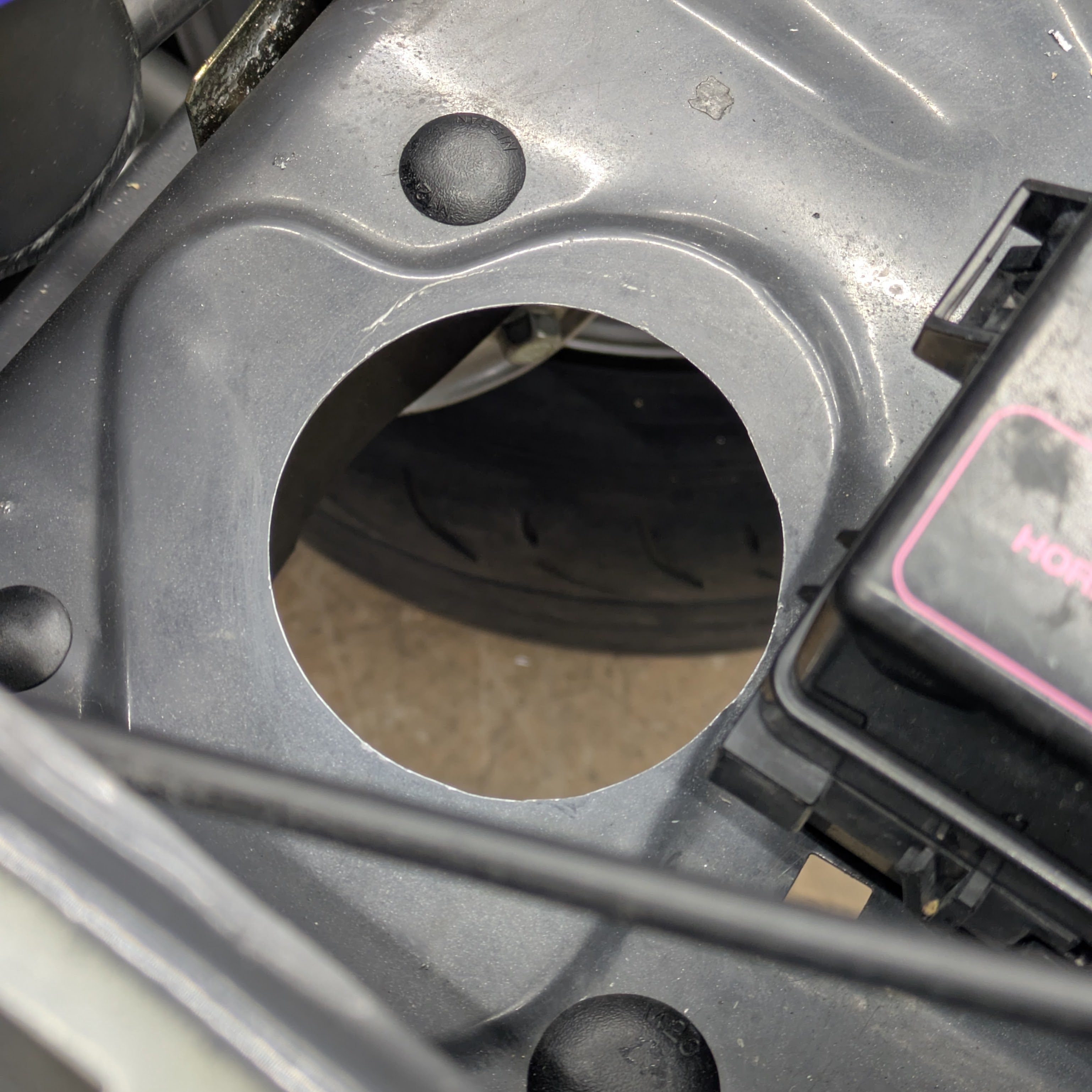
To rectify this, I wanted to step up to a 3″ hole, for which I had two options. I could either trace out the area that I wanted to expand, and use a combination of an airsaw and dremel to enlarge the hole, or figure out how to rig a holesaw in place to punch out the extra material.
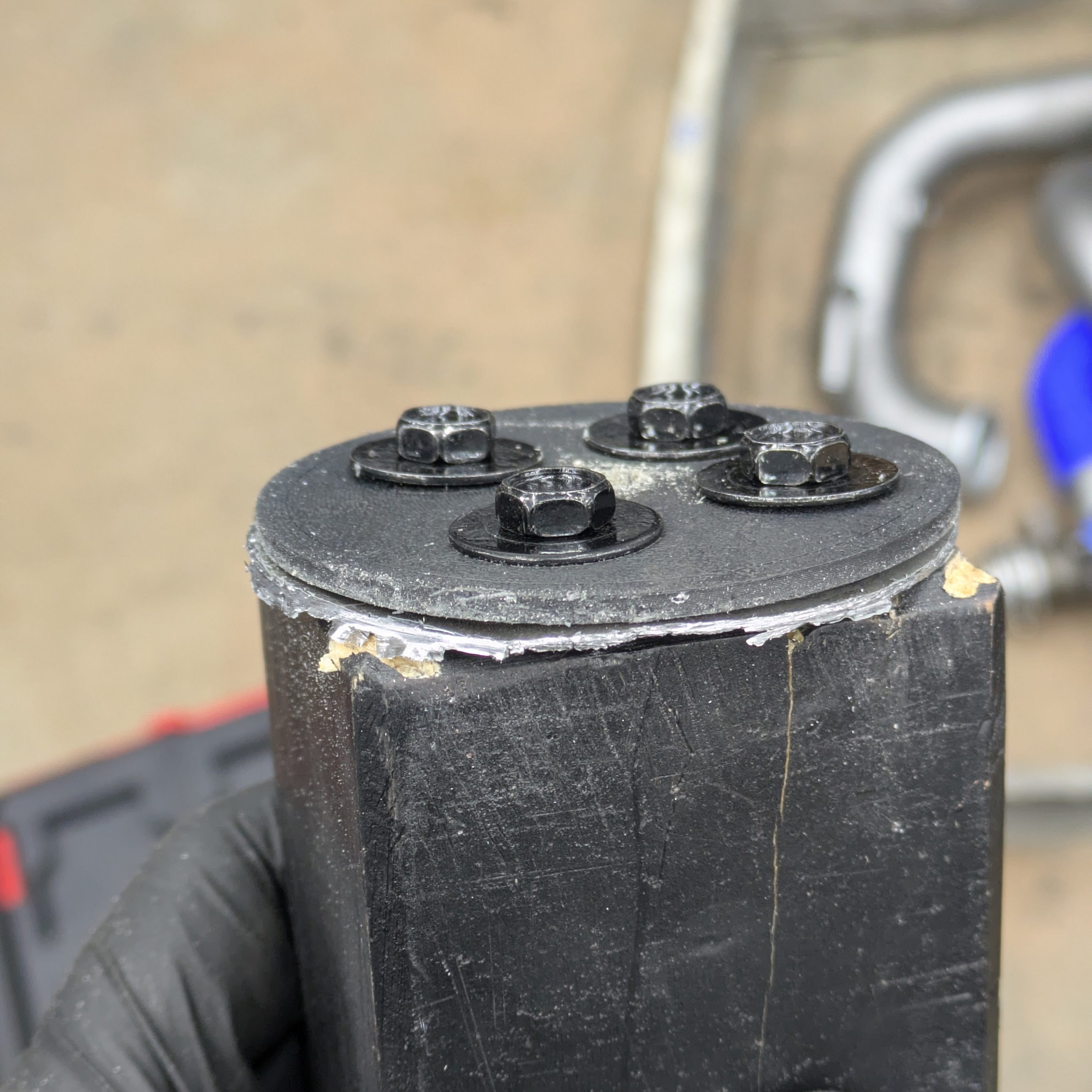
I ended up going with the holesaw option, but with some significant fixturing to make it work. Obviously there is nothing for the pilot drill to interact with, and I wanted to avoid attempting to visually center it as I knew that could only go poorly. I 3D printed a stepped disc that would drop into the hole and provide a centering template, which worked perfectly, however it didn’t rectify the support issue. I ended up screwing the template to a block of wood through the hole, then using a pre-drilled hole in the wood to maintain the alignment of the pilot. I cannot take credit for this support idea; that was all my father’s. It worked very well, and with some minor filing, paint, and edging to protect the coupler, it is now ready to accept the cleaned up intercooler pipe.
With the heat shield on and looking spectacular, I installed the air oil separator tank after it came back from powdercoating, as well as it’s accompanying return hose to the block. Brand new hose clamps and hose made it a dream, and the realignment of the metal drain pipe made it far easier to install.
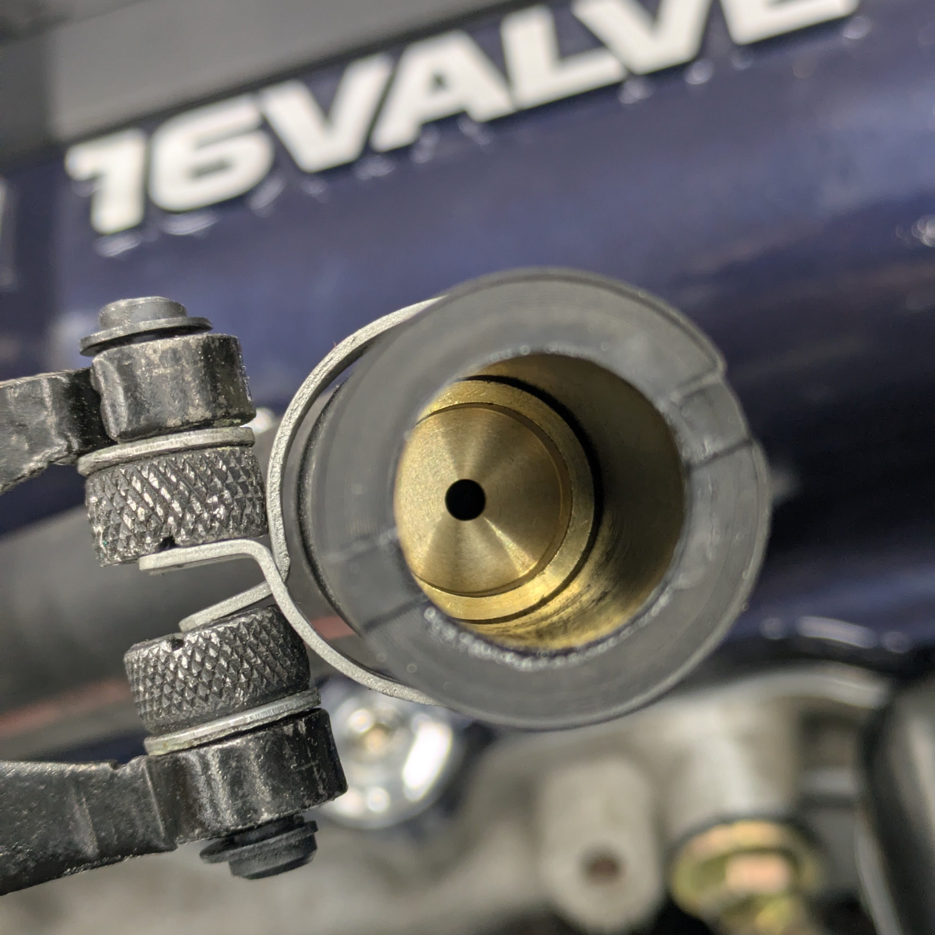
This is more of a PSA than anything: Everyone always talks about how crappy the T fitting is in the S13 valve cover, and while I do agree that the S14/15 covers are far better baffled, most people ruin their S13 setup by not running the right hose. Aftermarket manifolds mandate the removal of the AOS and thus the original hoses that run to the valve cover, and when changed, it also deletes the brass outlet restrictor that keeps the aerated crankcase oil from entering the T fitting all together. If that restrictor is retained, the heavy breathing from the crank case shouldn’t make it to the valve cover at all, or at least in a very minimal capacity. You can still purchase this hose new from Nissan with the restrictor, and I am hoping it’ll make all of the difference in actually keeping oil contained in the system.
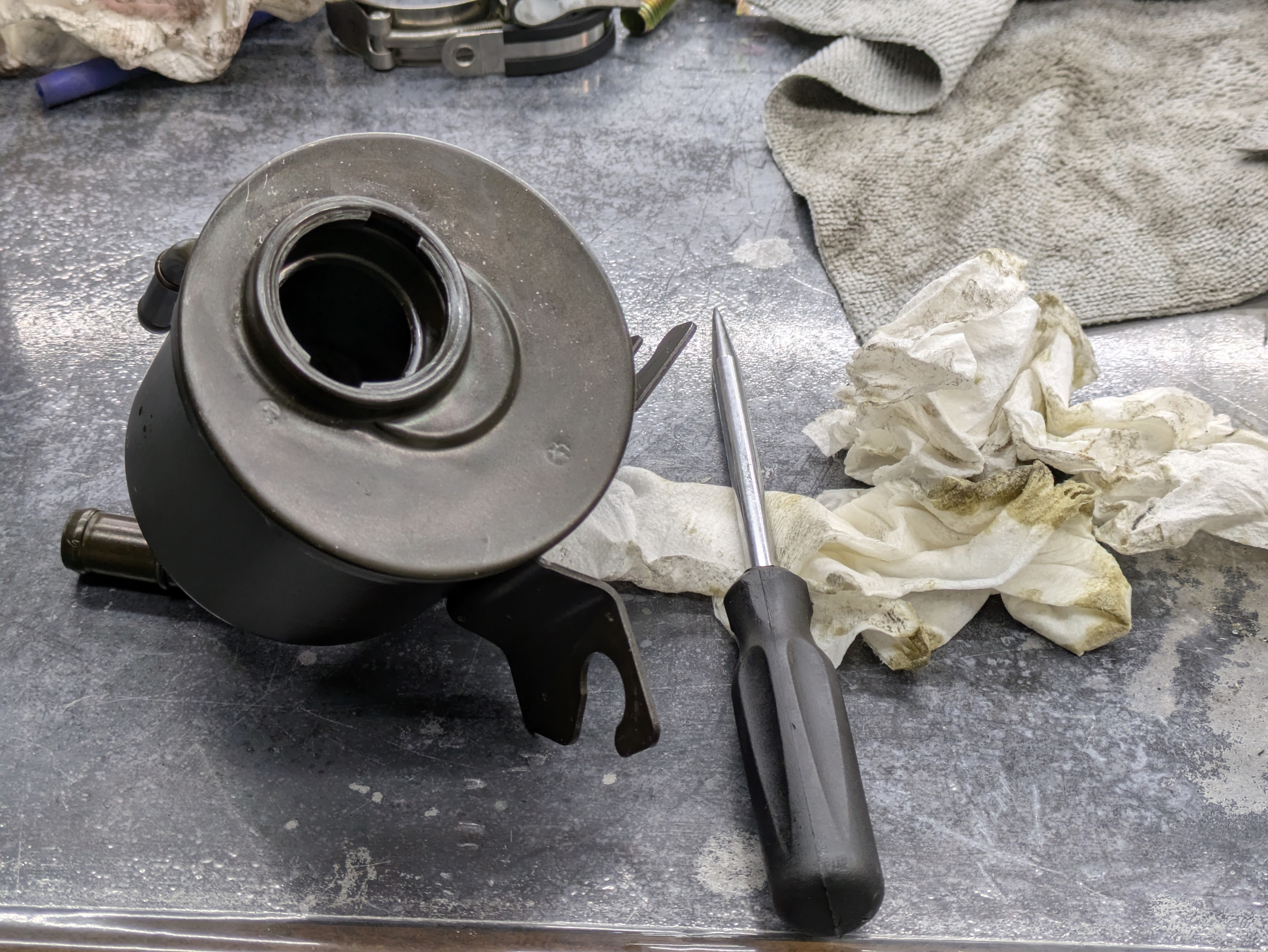
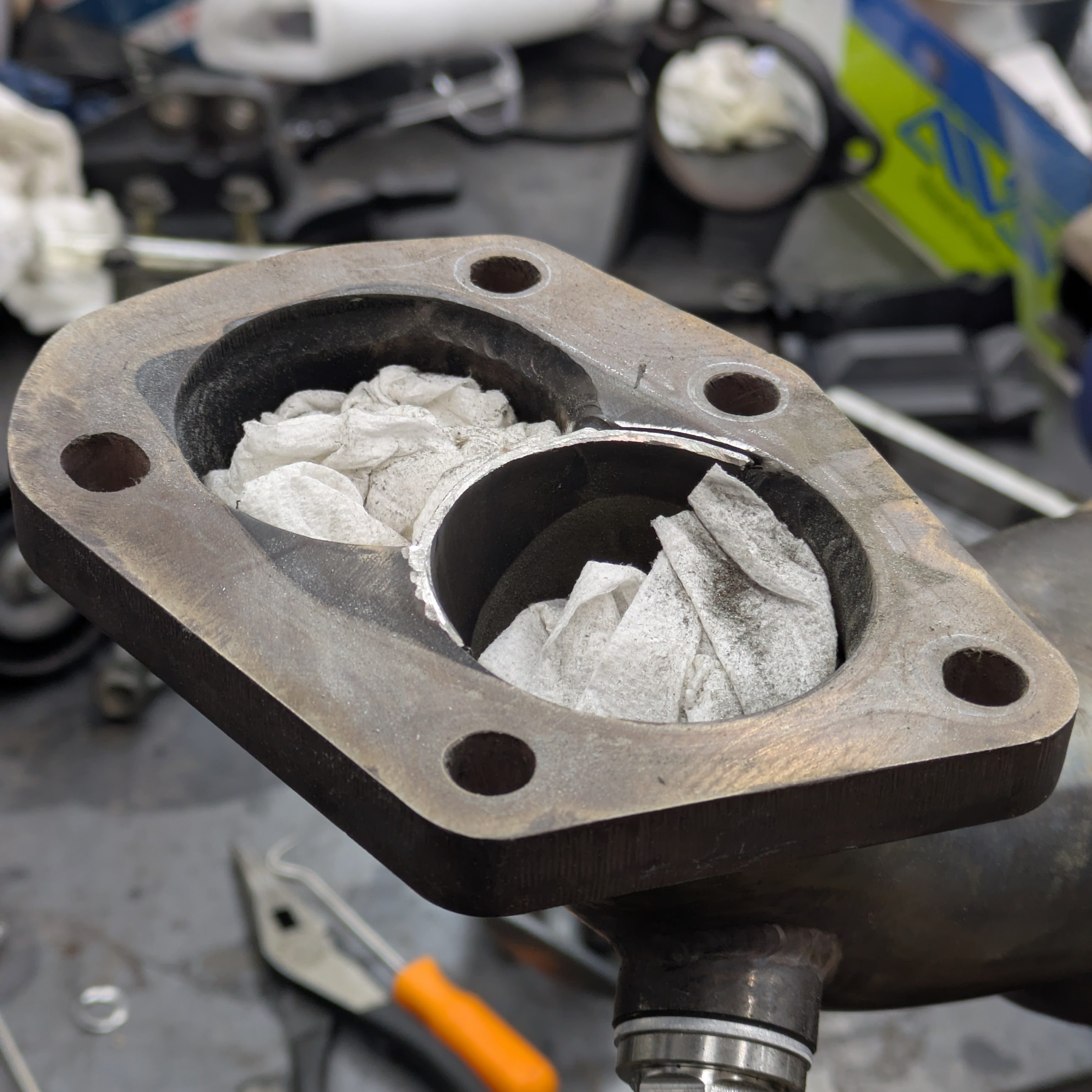
While I had filled every other fluid earlier, I didn’t have the required Dex-Mec ATF required for the power steering system. During the steering rack install, I learned that there was previously power steering fluid in this car, not ATF, which could explain some of the crossover reaction issues and maybe the leaks that the car was experiencing. Its all theory crafting at this point, but I knew I had to make it right. I flushed a ton of kerosene and brake clean through the reservoir to get it cleaned out, and resorted to shoving paper towels in and moving them around with picks and plyers to clean 100% of the internal surfaces. I didn’t end up removing the inlet filter inside the res (for fear of breaking it) but I was able to clean every screen on it.
With the reservoir cleaned up, I reinstalled it on the existing lines(one of the few things I was unable to replace due to parts being discontinued) and filled it with all of its fresh screens. It is very likely that this system will be changed again once the car running and tested for the Faction! power steering cooler kit, but that is a problem for later Thomas.
With all that being done, going to let the (pretty much) finished product speak for itself. Rapid fire comments for undiscussed stuff.
All of these small projects, now summarized in one place, was a monstrous amount of work. There were moments that I questioned my own tendencies, but those nights end, and after the annoyance diffuses, it’s all worth it. The effort was not unrewarded, as after some trigger setting changes, the car started and ran perfectly on the first try.
I am truly stoked with the way this engine bay came out, both aesthetically and functionally. It houses all of the early 2000s era parts and trends, with the ergonomic functionality and durability of a modern track car. My only complaint is that it could look busier, but that is only to appease the traditional Japanese style, and I have a hard time doing somewhat unnecessary/inefficient things just to fill space.
The largest hump with a new car for me is all of the unknowns. What’s lurking under the intake manifold? Where do those wires go? Is there a hose being pinched somewhere? Not knowing how things are configured is the reason why it takes a while to get comfortable really thrashing on a car. But now I don’t have to worry. I know it’s all done right, or as right as I can possibly do it.
Now all I have to do is finish the rest of the car and drive it. Really fucking hard.
A lot more coming soon.
Until next time.
