
This is a hodge podge of unglamorous, uninteresting, and unnoticiable improvement to the vast majority of people. It’s also out of sequence with articles as I already published the process of putting the motor in. But progress is progress, and these little details needed to get tackled so that the bigger parts could go back in. Think of it like prepping a canvas, or making pizza dough, or making the cake before frosting it…
I’m hungry. Anyways.
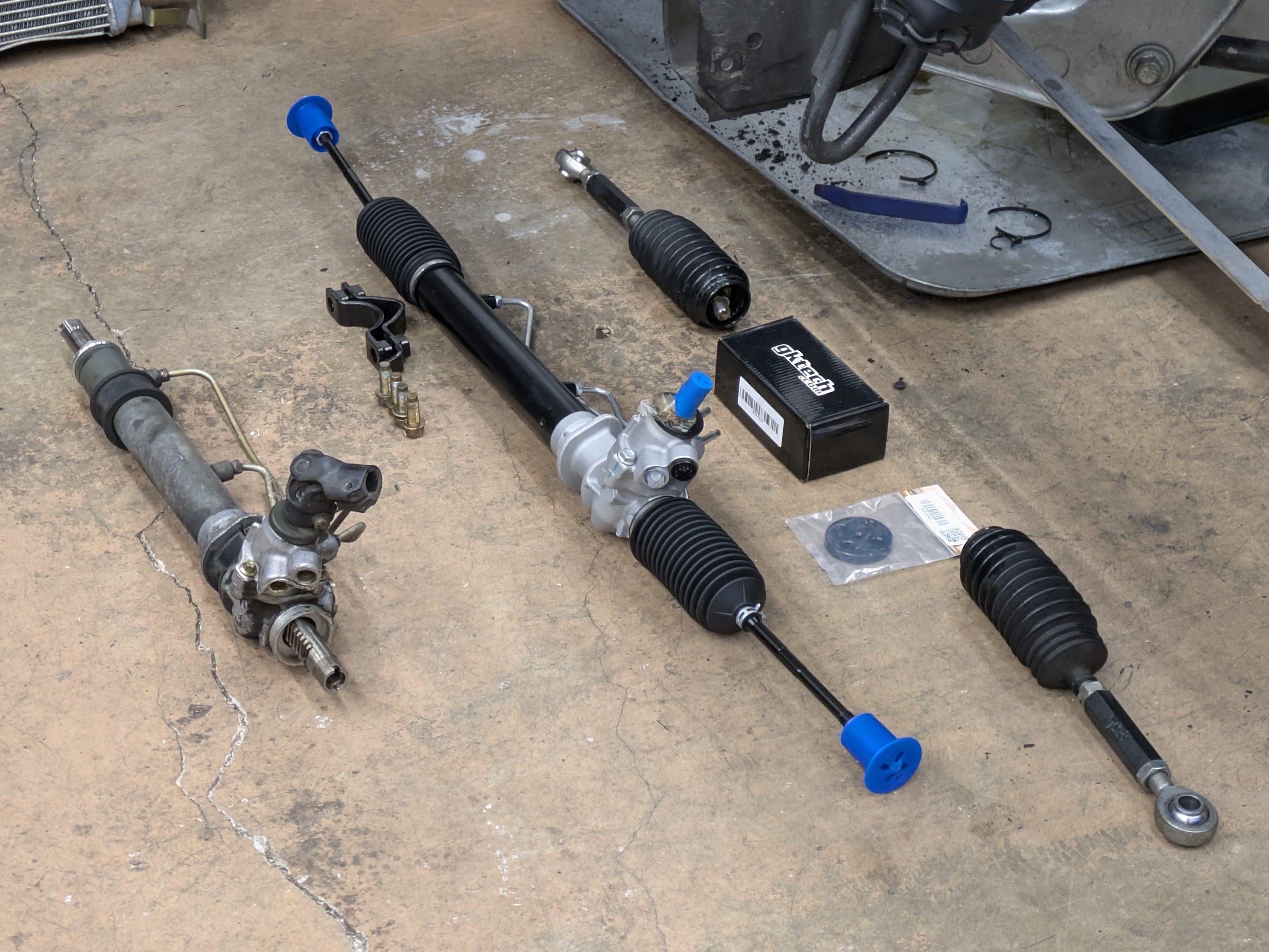
I will start by saying that this was probably unnecessary. I saw some slight weeping from both rack boots, which prompted me to immediately overreact and buy a brand new steering rack. While I probably owed the old rack some time to get reacclimated to a life of hard driving before I judged it’s sealing abilities, I knew a rack swap would be far easier with the motor out. I ended up with the K-Fab rack, mostly because I was already ordering from Faction! and it was the easy button. They all seem the same minus the T^3 rack being double the price.
Upon removal of the old rack, I was greeted with hidden grease and grime that was previously inaccessible while cleaning the engine bay. It was promptly cleaned and made ready for the new rack.
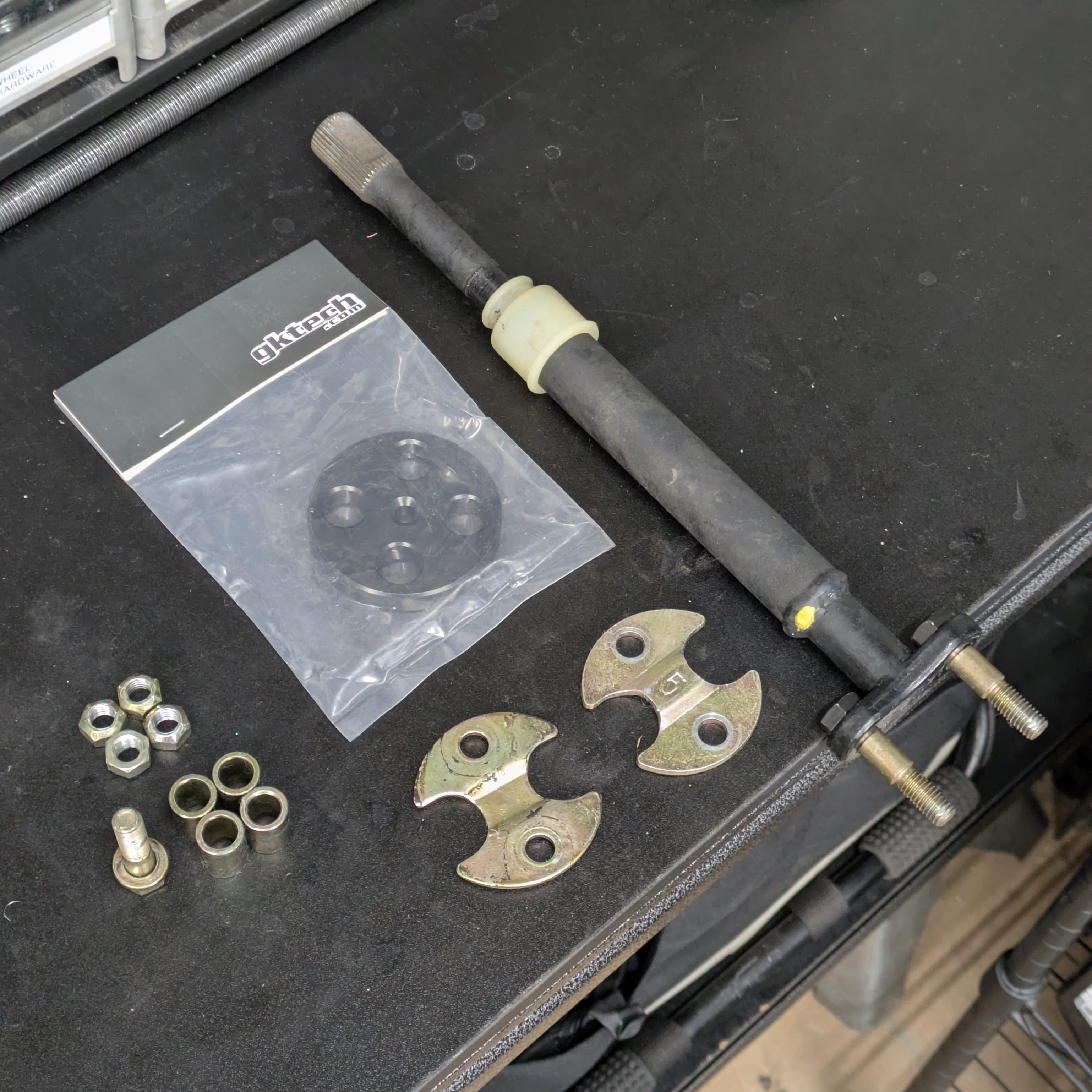
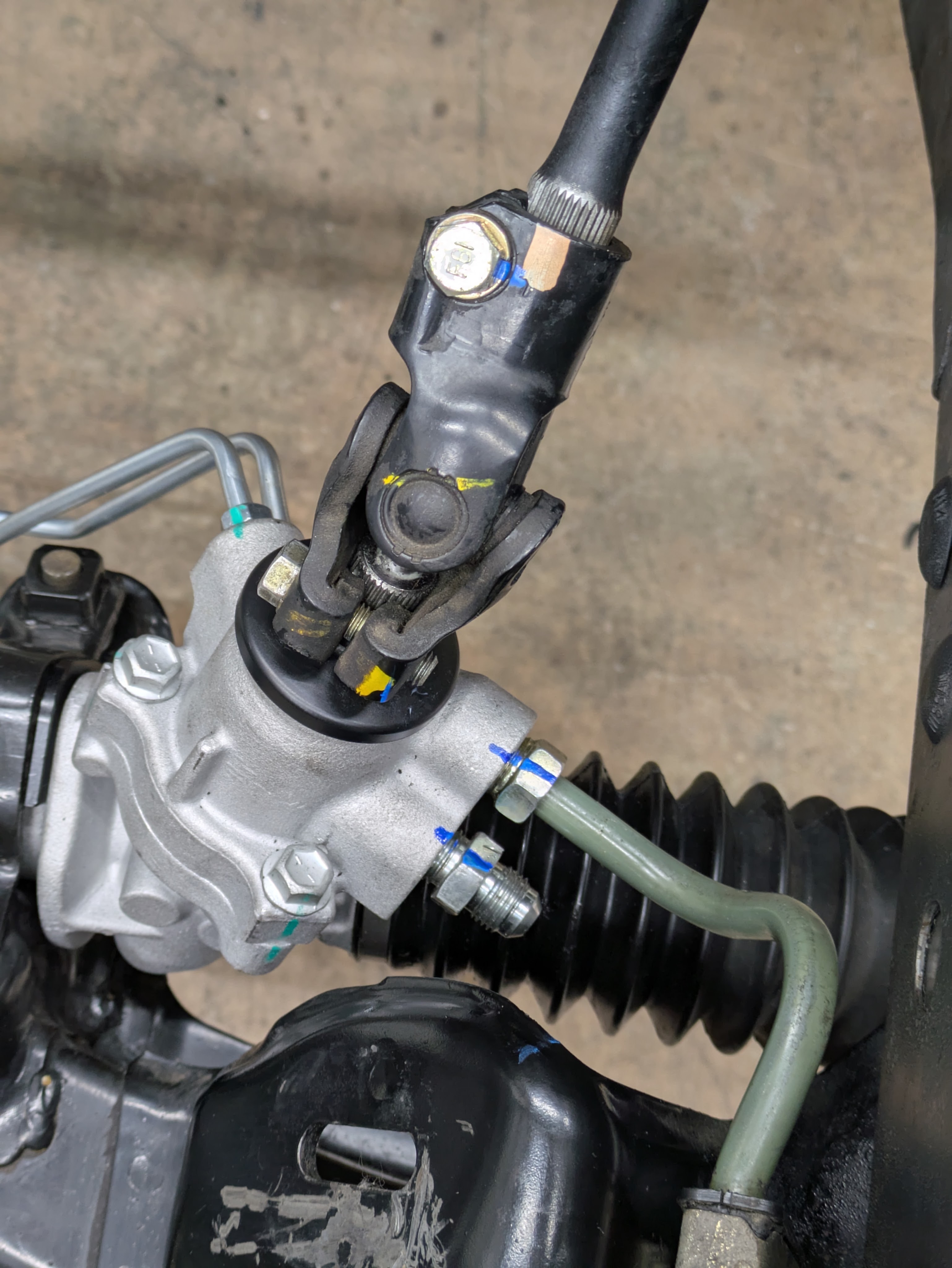
While the rack was out, it was time for some updates, namely to the 30 year old rubber steering shaft bushing that isolates the steering shaft near the firewall. While mine was in good shape for it’s age, it was the best time to do it.
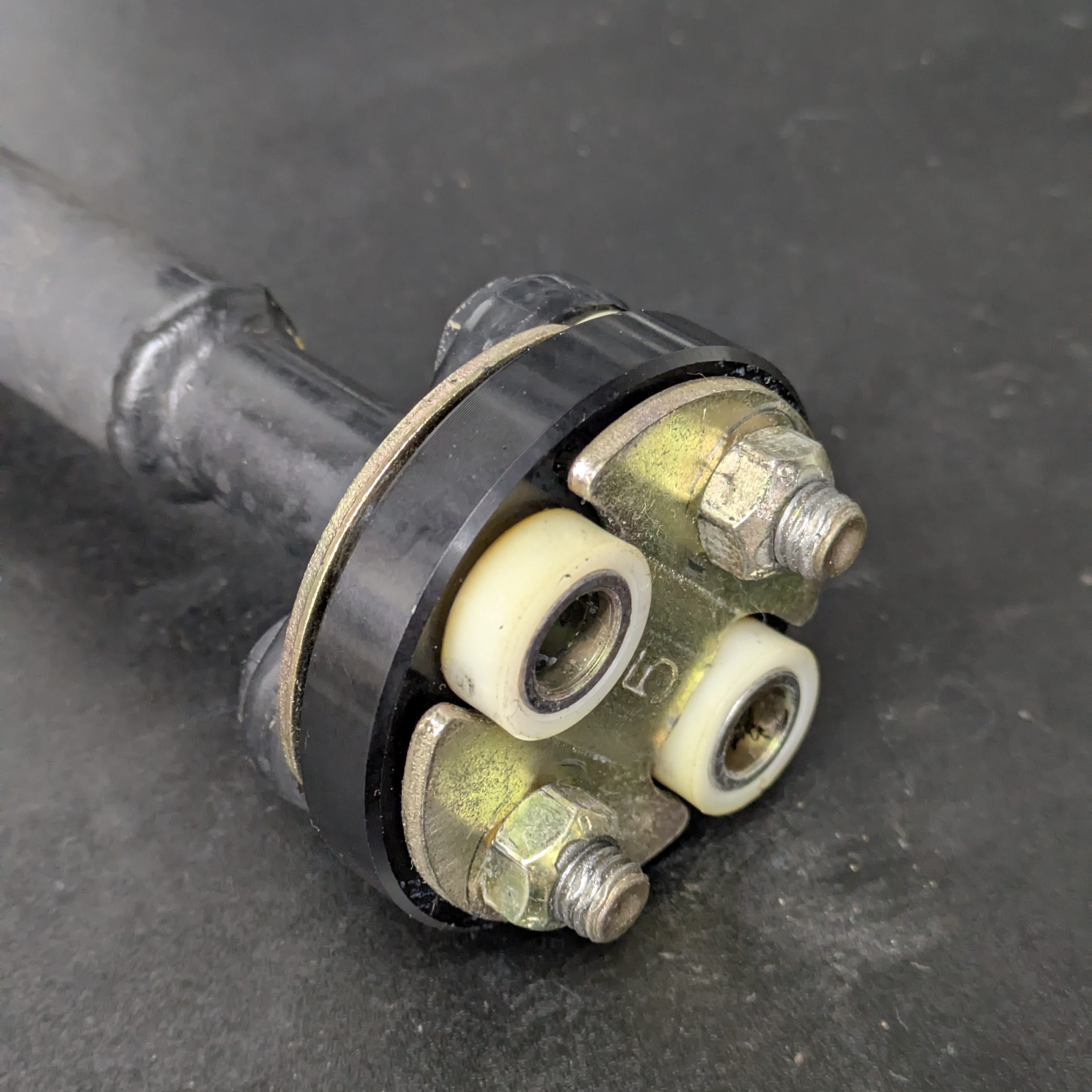
Not going to lie, the GKTech solid replacement kind of fit like shit. The factory press fit sleeves ended up taking massive chips out of the bore which was not the most fun thing to install. Rather disappointing, and I would recommend other products on the market as a result. This was lumped in with the big Black Friday purchase, which is why it was ordered in the first place.
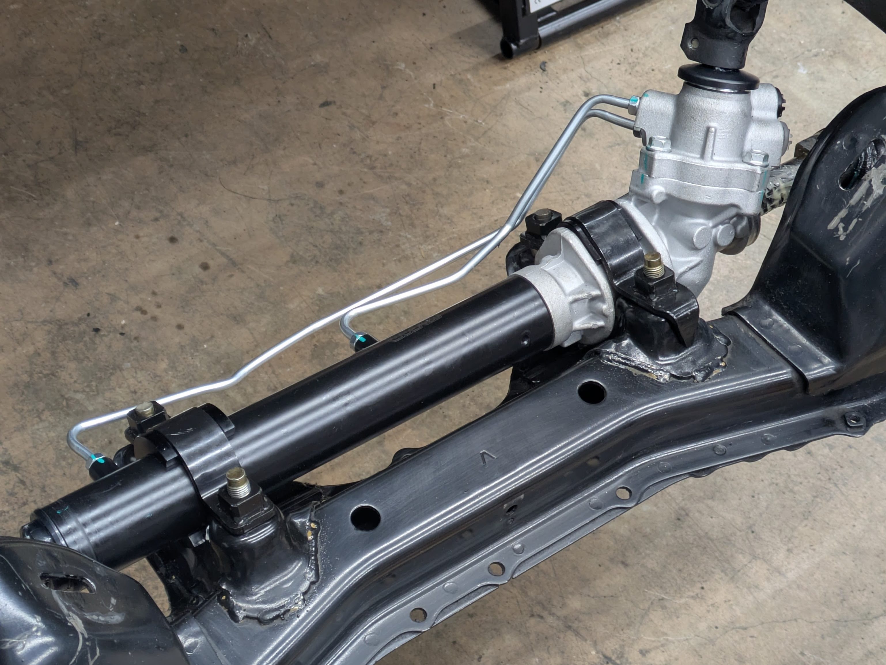
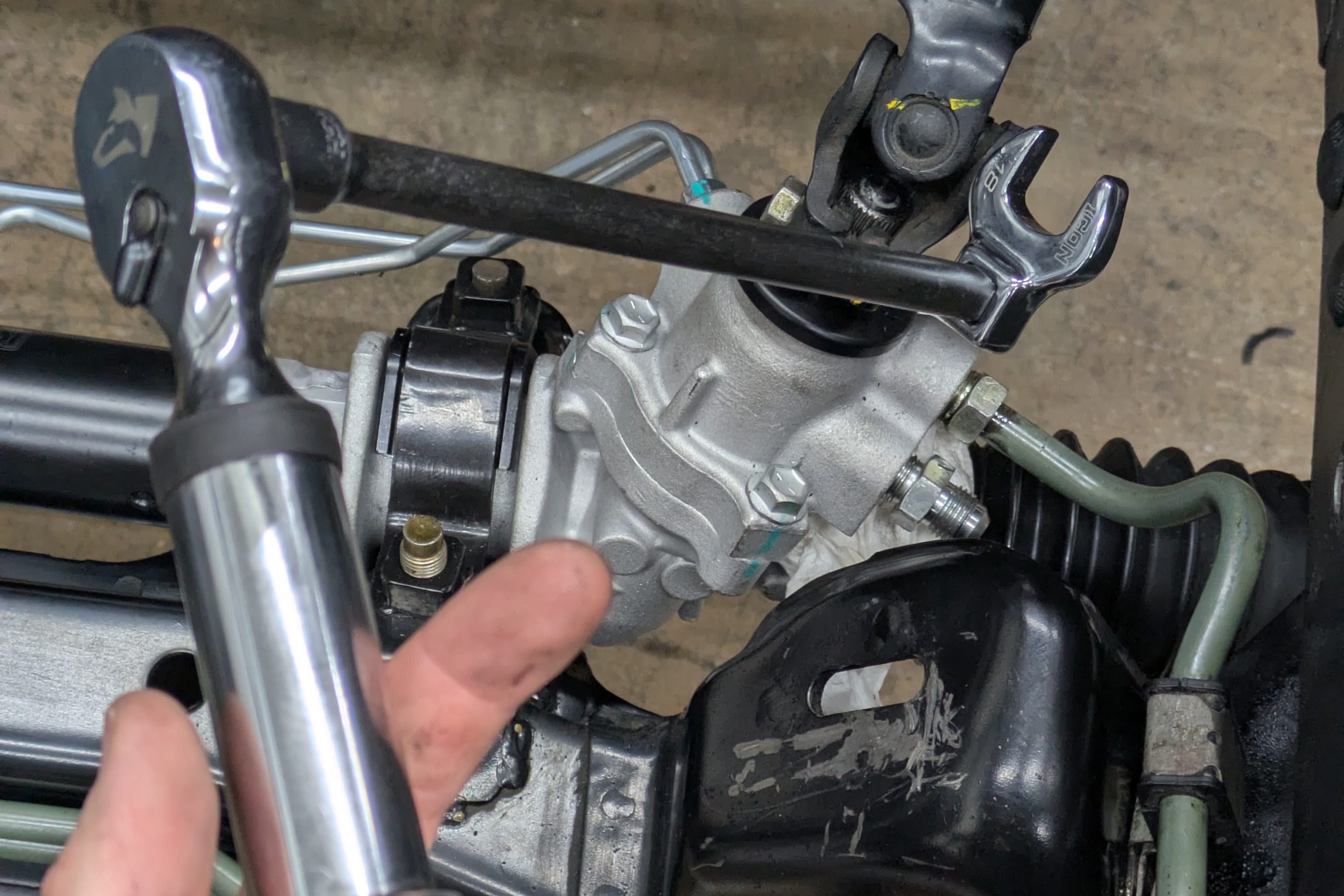
With the refresh of the steering shaft and cleaning of the subframe complete, I threw the new rack in. It fit great, and with the inclusion of the GKTech solid rack bushings that move the rack up and forward for better geometry, it was pretty much as good as you could ask for.
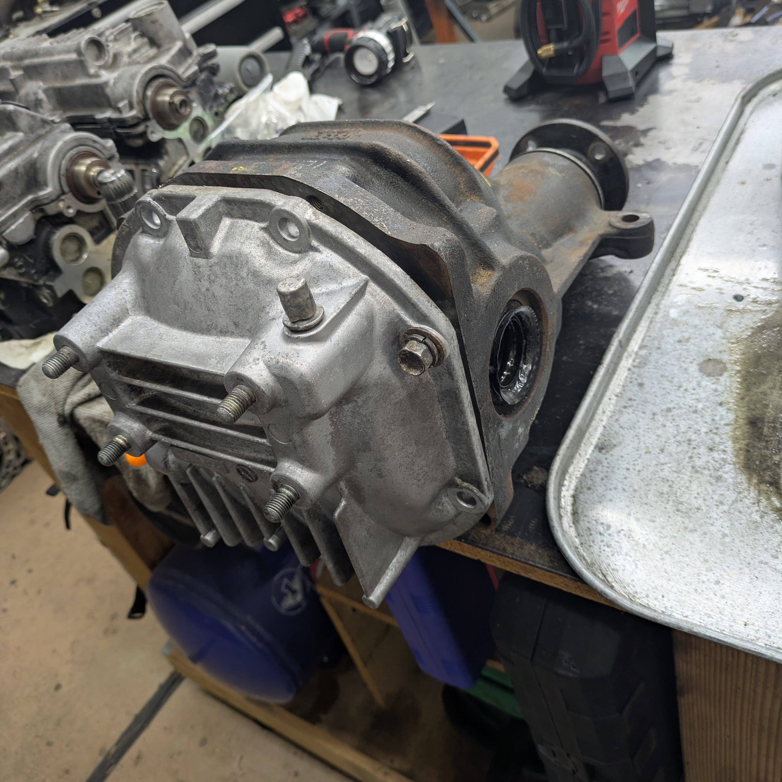
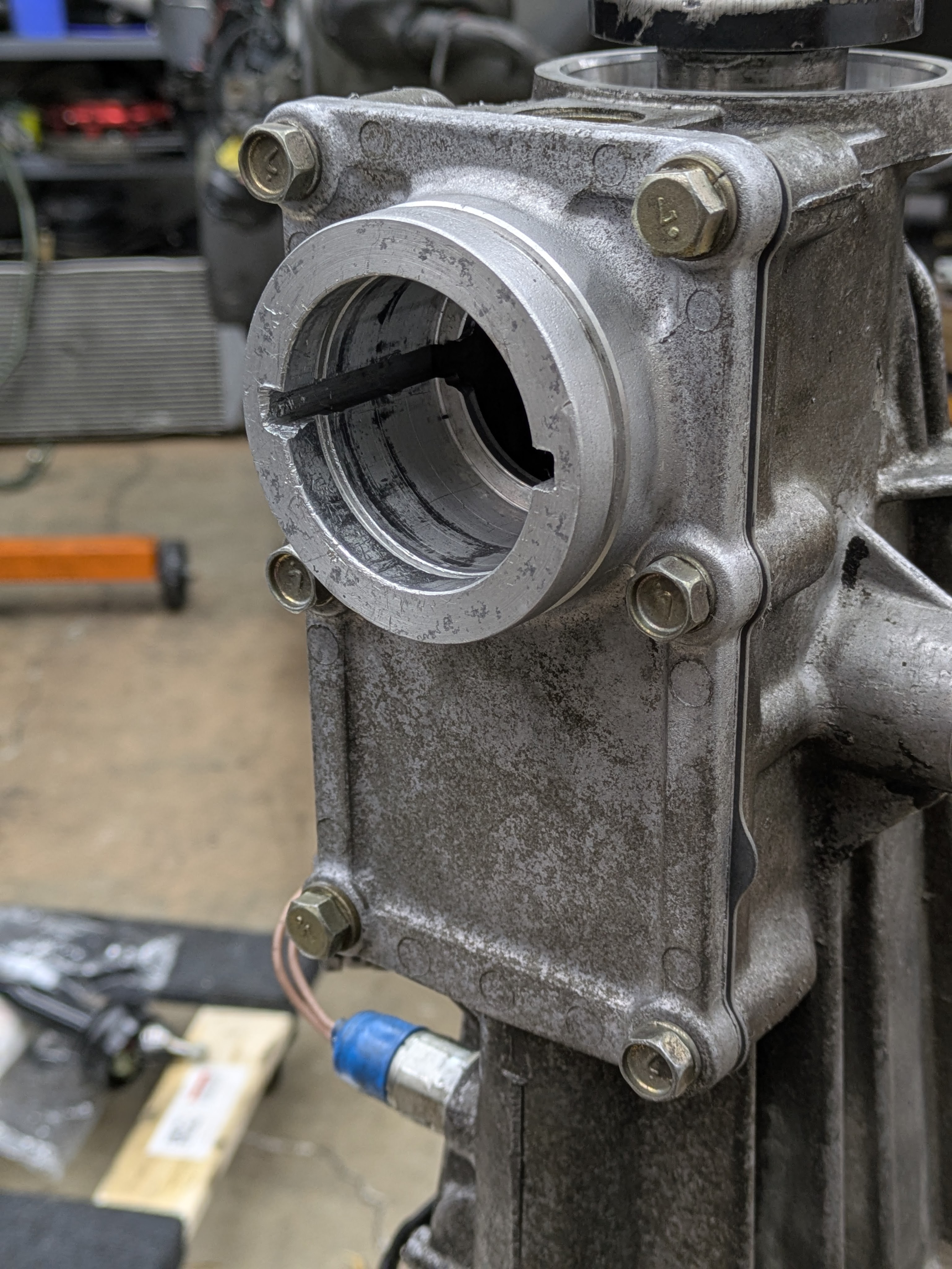
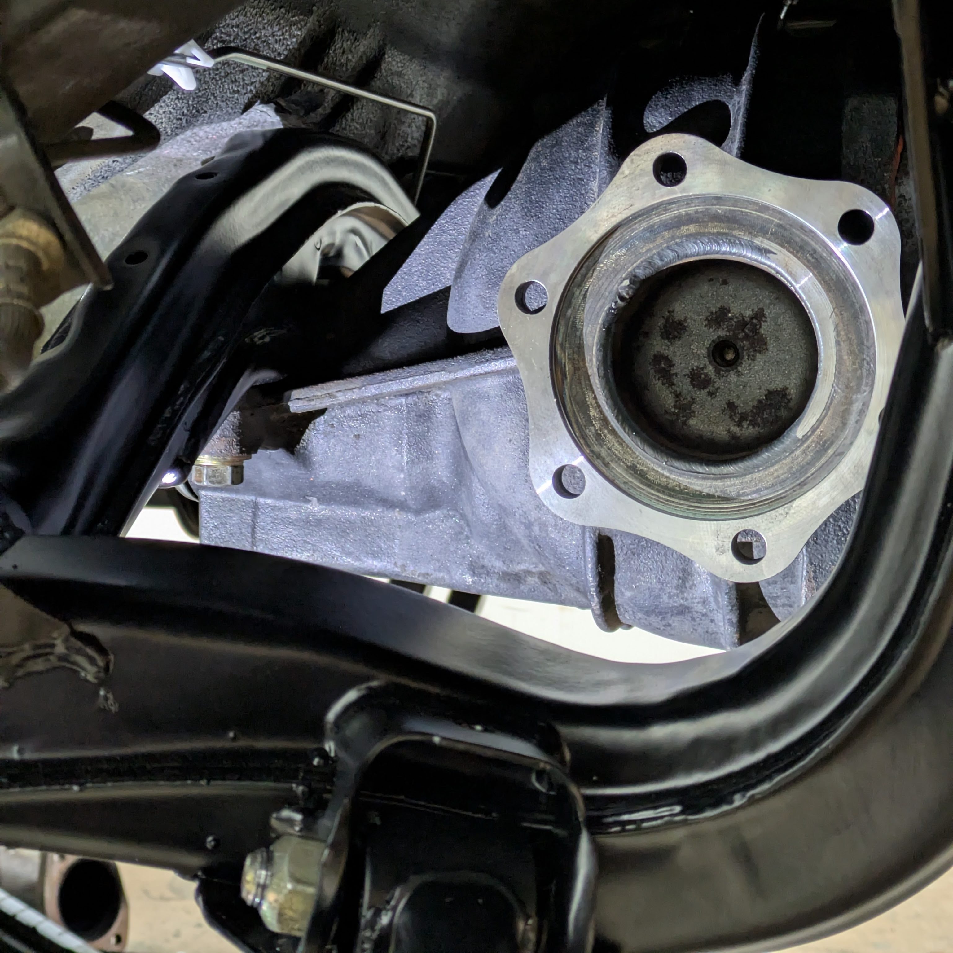
Circling back around to the diff – I had previously taken it apart and cleaned it when I pulled the car apart, but it lied dormant as I didn’t know how to address it’s issues. The reseal that was required was straightforward, however the stub shafts were another story.
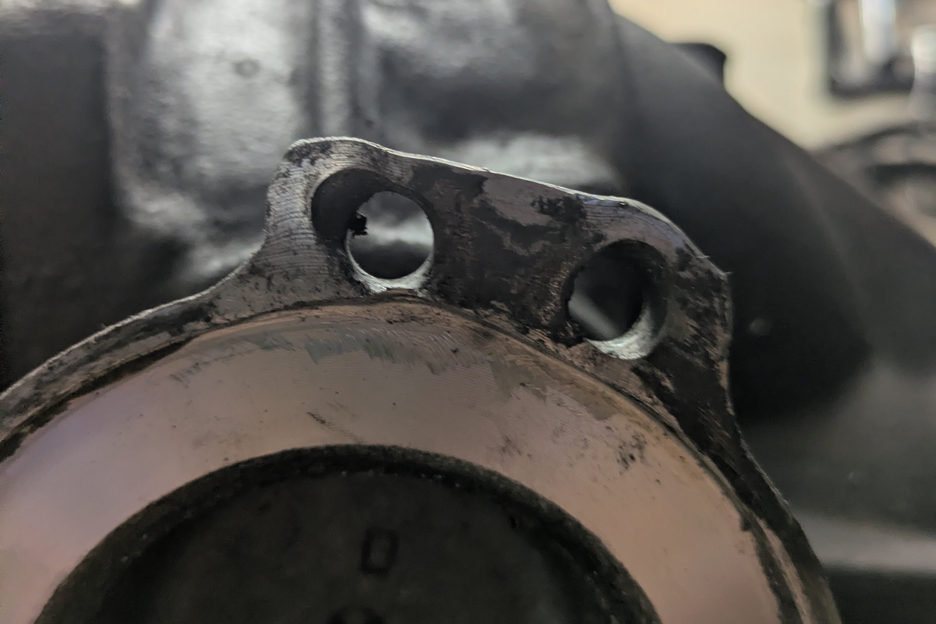
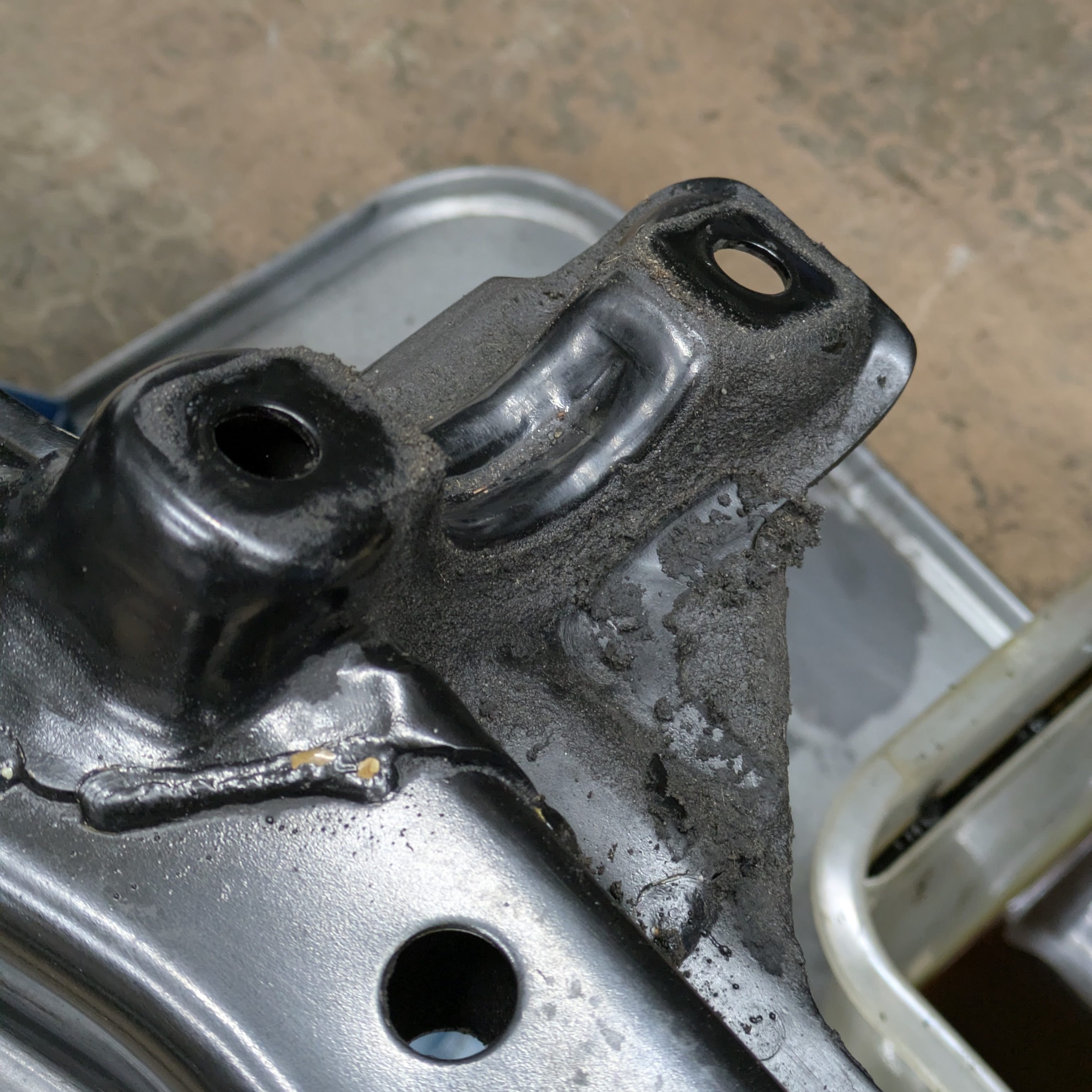
The stubs, from a previous incident before my ownership, were severely damaged by what appears to be a bolt coming loose. This both elongated the hole and bent the flange to where a factory axle with factory hardware no longer felt kosher; The stub shafts needed to be replaced.
After a night on the phone with the knower-of-S13 Alex, we determined that I had S15 helical stub shafts, which aligns with the era in which this Nismo Mechanical 2 way diff was released. Unfortunately, this put the stub shaft rarity at an all time high. Fortunately both Japanese sellers that I messaged requested measurements, since there are so many different stub shafts for these cars, and we were able to determine that none of them were compatible before money was exchanged. I’m grateful that they did honest business, but annoyed that no one had what I needed. I didn’t want to scrap this perfectly good diff over externalities.
The solution to this problem was concocted by Alex, full credit to him. I didn’t even remember it existed until he mentioned it.
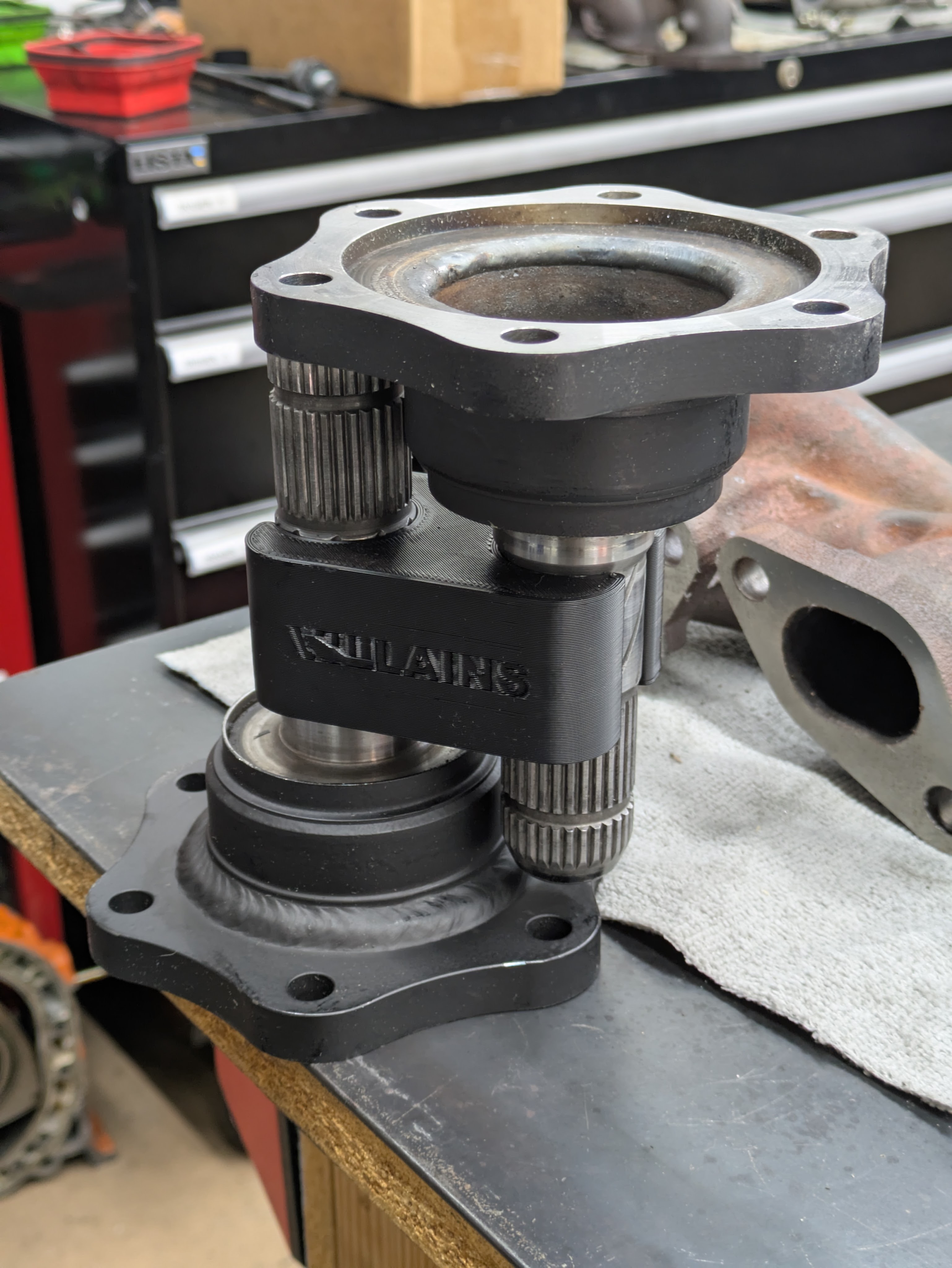
The most logical next step to save the diff and use the good parts of the buffalo was to convert the car to Z33 axles. Since the rest of the stub shafts were in great shape (sealing surfaces, splines, etc), you can send the stubs out to be cut and welded to a beefy flange that accepts the more modern, stronger 350Z axle. I chose Villians for this service as they have been doing it the longest to my knowledge, and they are locally owned and operated in Washington.
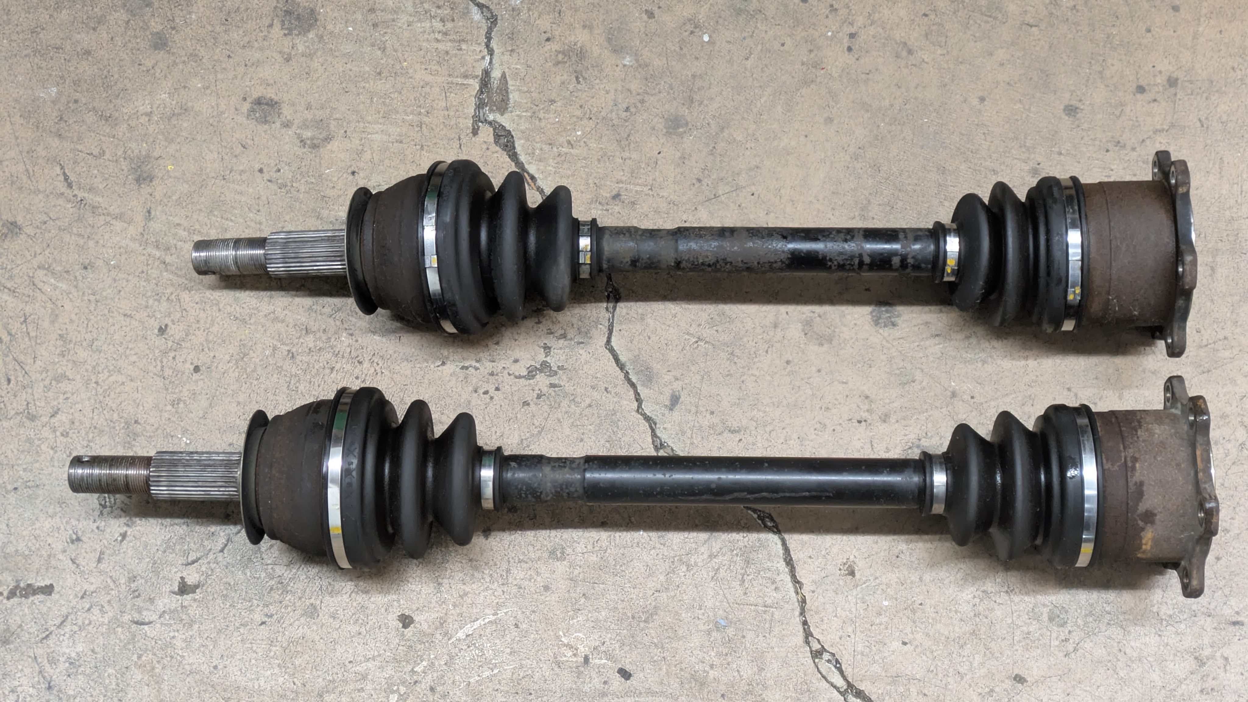
While the primary attraction of this conversion for me was the retaining of the differential, the side benefit is stronger axles with better boots that are easier to get. Most every autoparts store has 350Z axles, and any drift event should have a few floating around. While I don’t make enough power to hurt even the stock axles, it’s a good modernization with an improved boot design and the update from tripod to Rzeppa CV joint. I’ll still retain my stockpile of OEM tripod S13 axles for if I build an OS Giken in a new housing for this car (I almost certainly will).
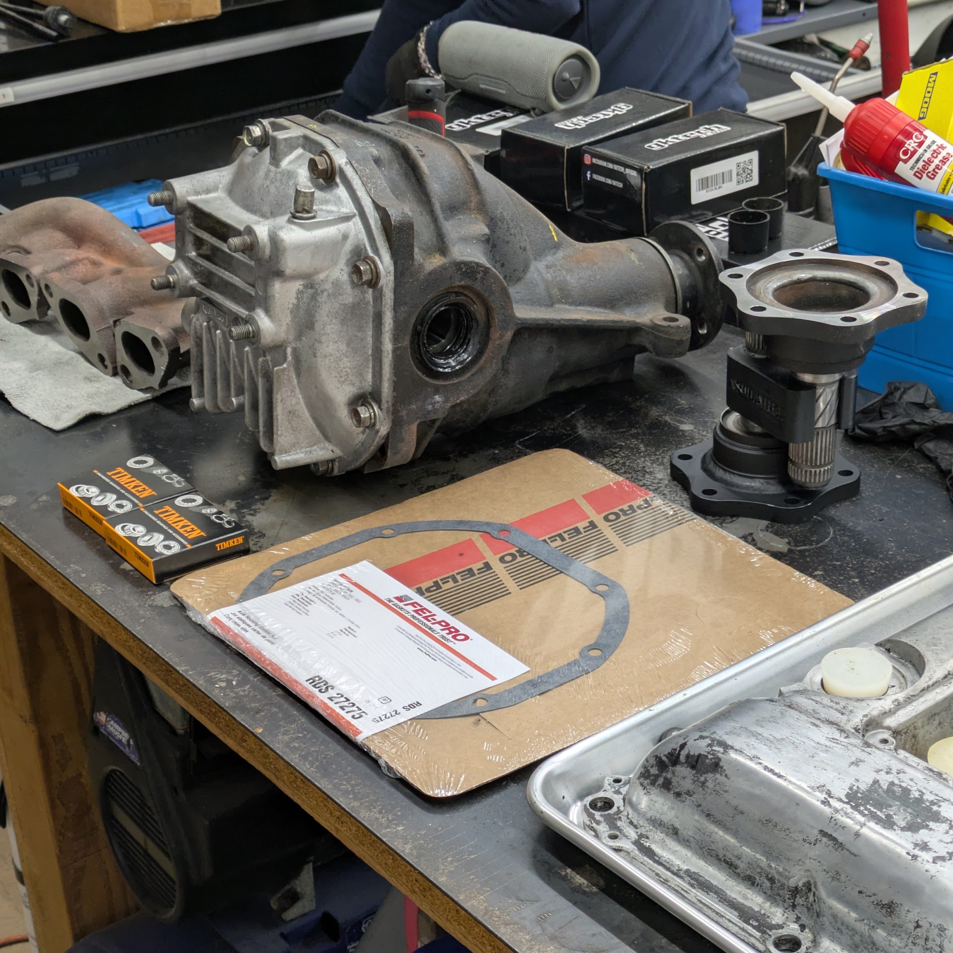
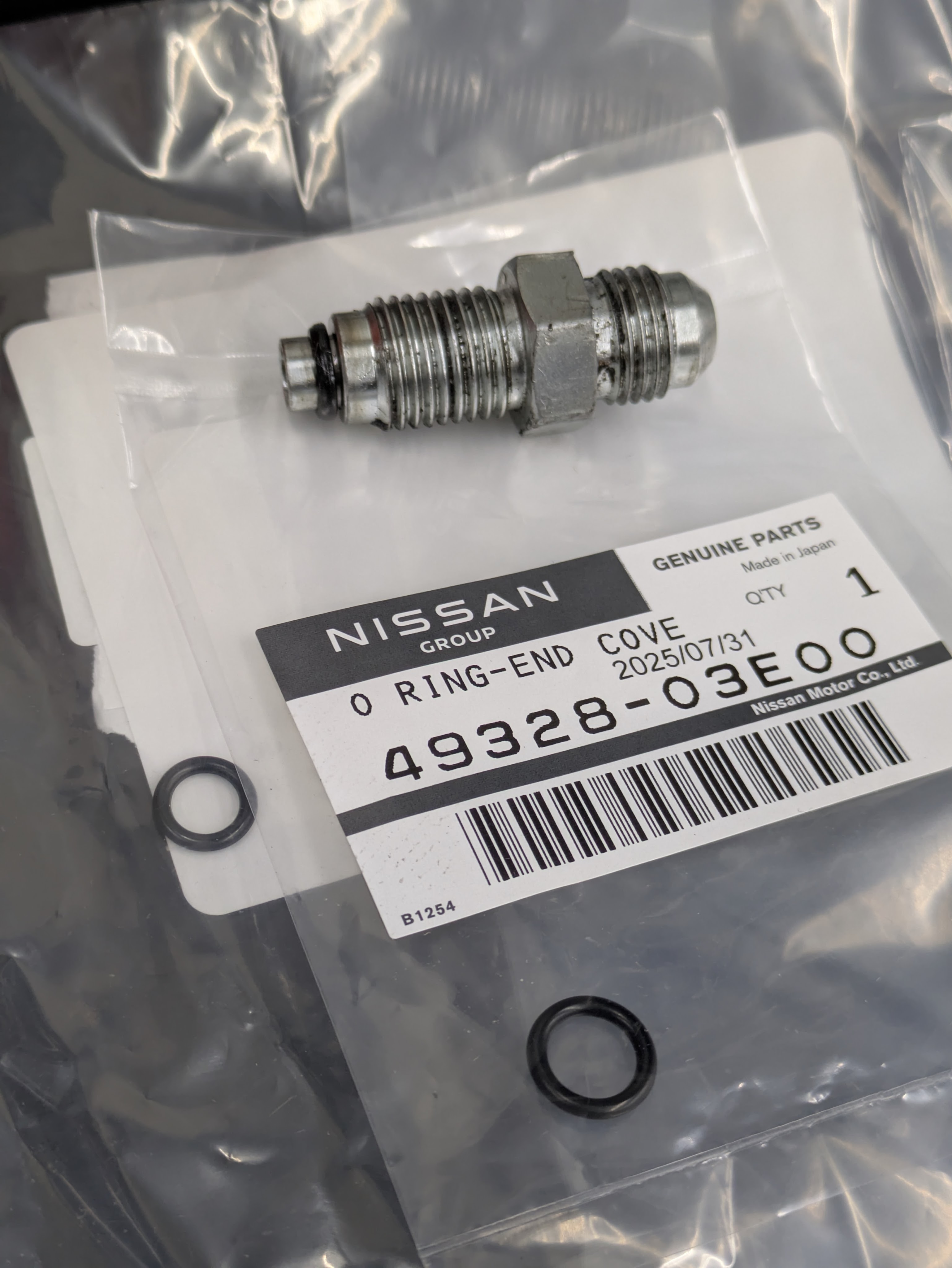
With the big hurdle out of the way, I threw the diff back together with new axle seals, a new diff cover gasket, and my new stub shafts.
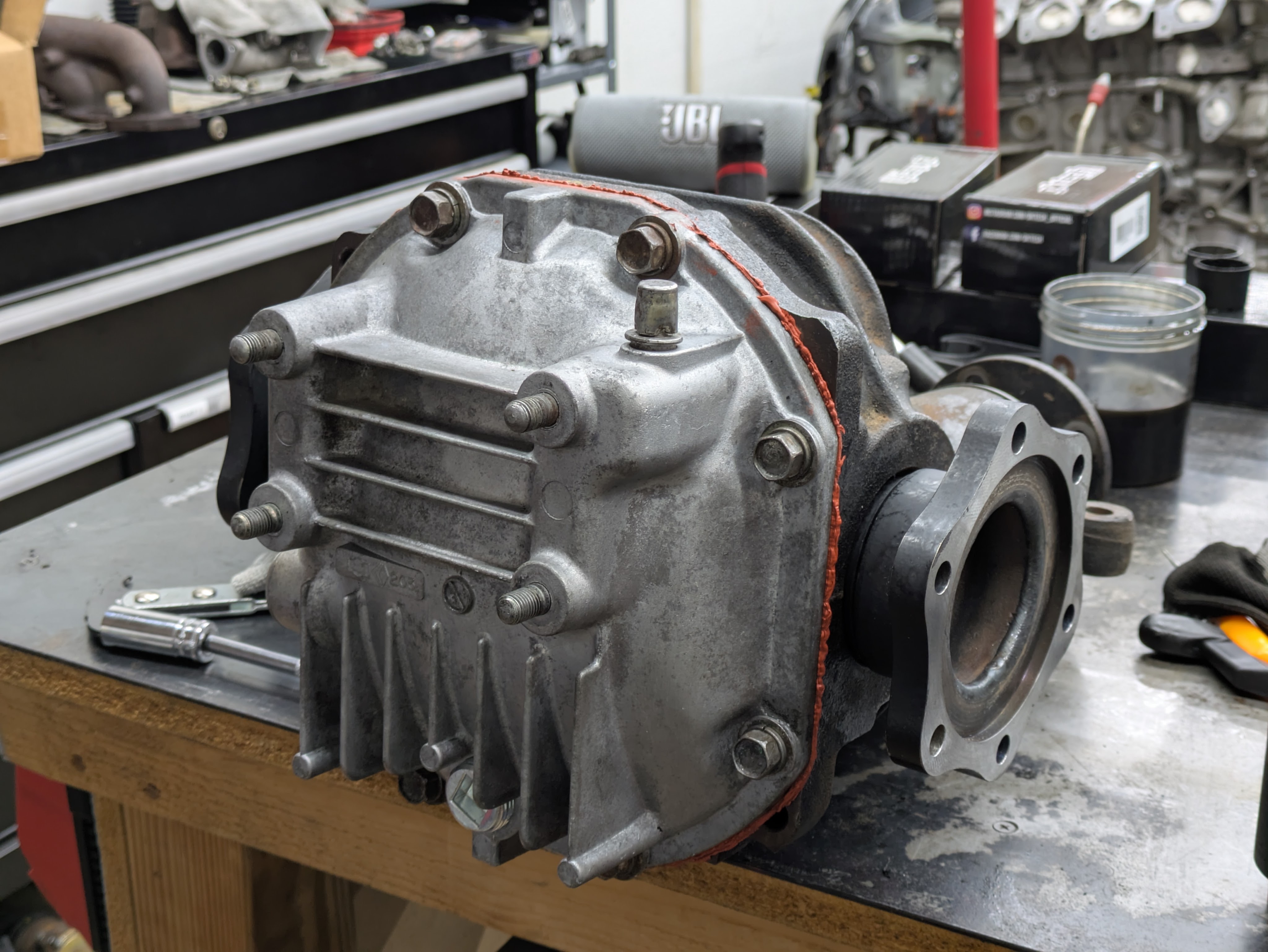
I opted for the heinously colored yet effective Nissan OEM RTV for a light skim coat on the gasket to take up imperfections. No one else will see it, so I can live with it.
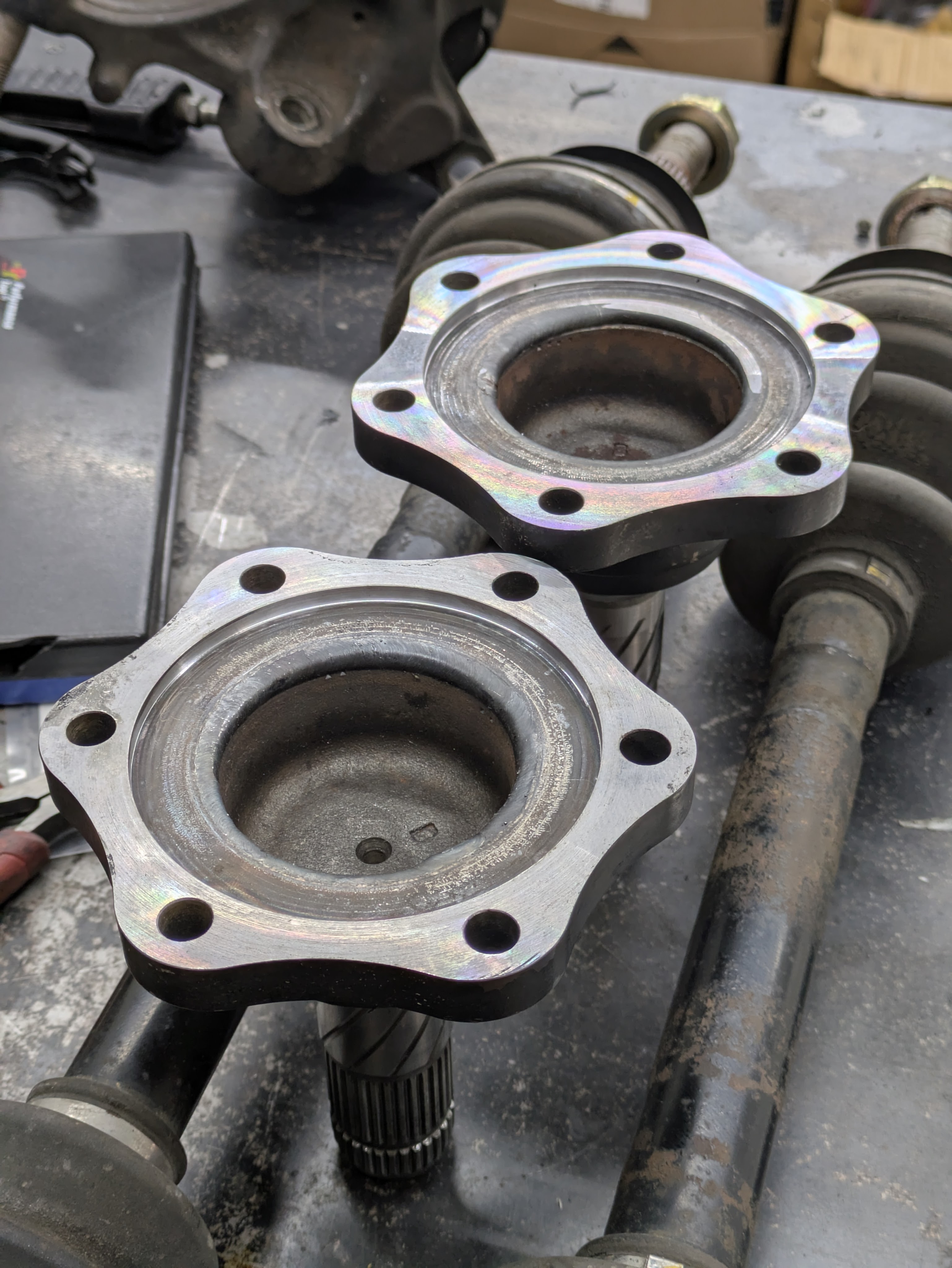
There was only one problem: during a dry mockup, I discovered that my stub shafts didn’t actually interface with my axles properly. I measured it all and found that the stubs were about 0.007″ undersize, causing the rear cap of the axle to not sit within the counterbore. I shipped them back to Nate and he made it right immediately, so props to him. Once the second machine pass was complete, they dropped right in like factory.
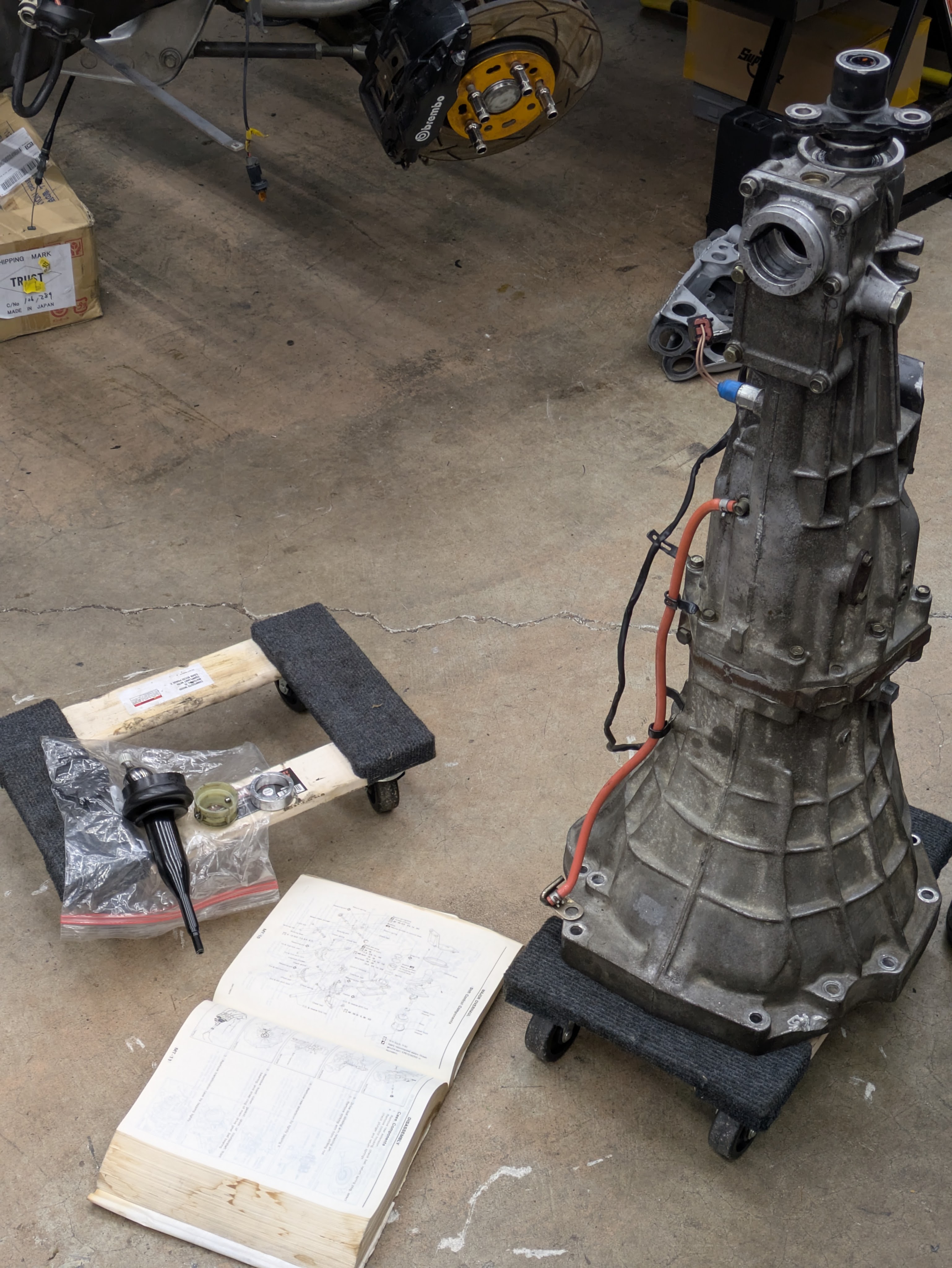
In a similar vain to the differential, I wanted to do a once over on the transmission. While not experiencing blunt force trauma that needed significant resolution, I had a few bits to add to it. I had already addressed the seals and exterior surfaces when the transmission came off to do a clutch last summer, so this was smaller details.
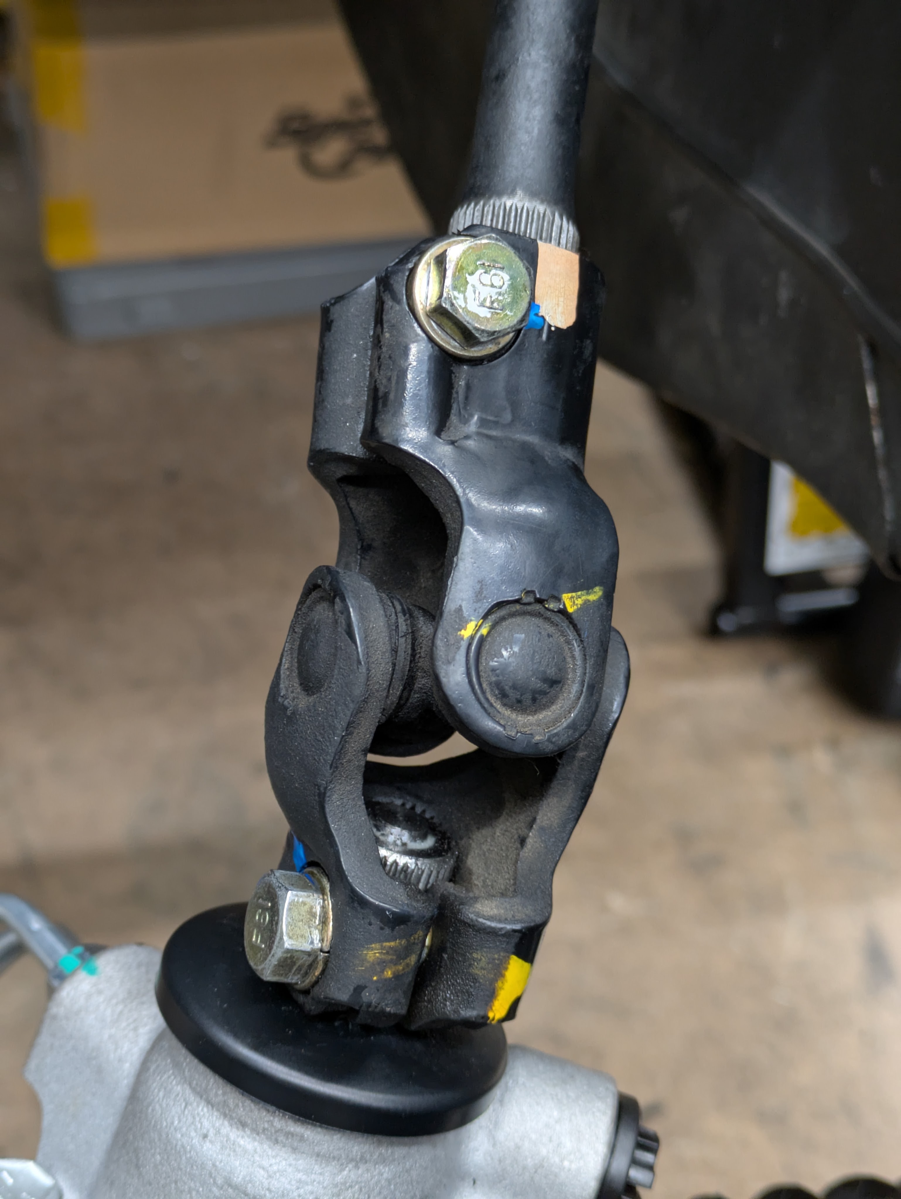
The shift lever pictured is a Nismo Solid shifter I purchased with my engine. I was missing a few of the components, namely the snap ring and wave washer. After digging through my FSM, those parts were on order, so I threw on a shifter gasket as I believe it was weeping. I was chasing a leak that I thought was the output shaft seal, but it was clear that it was coming down from above it.
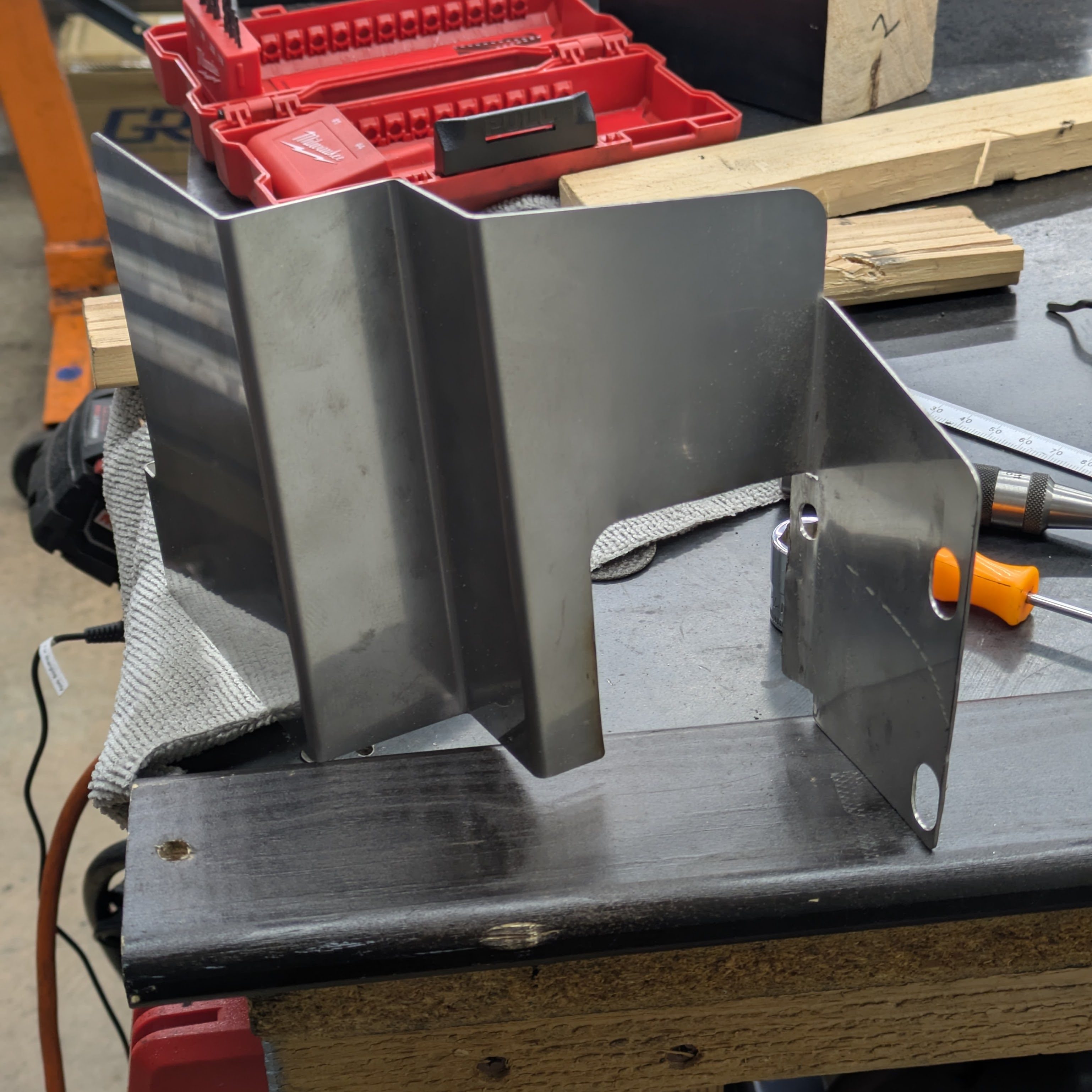
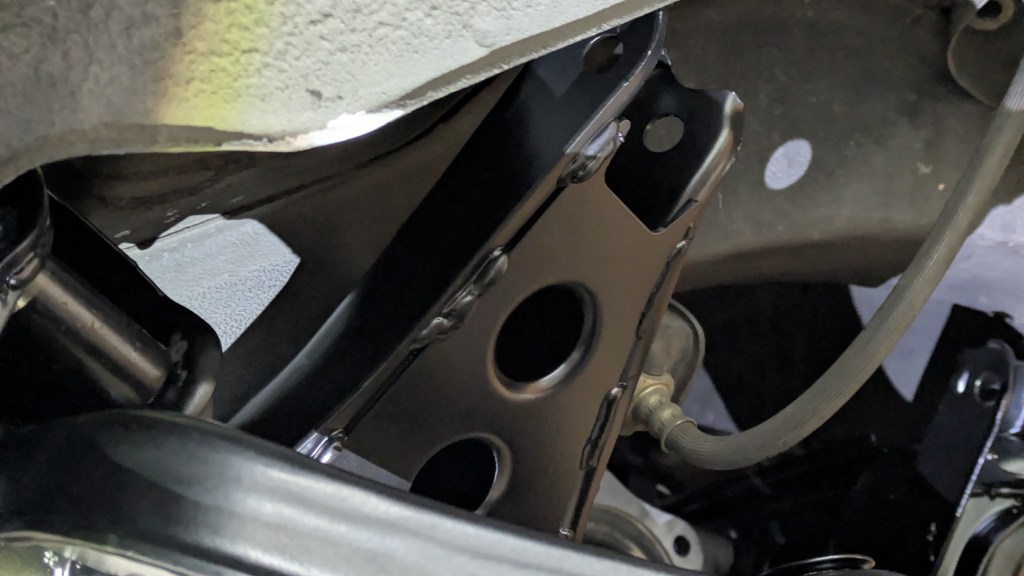
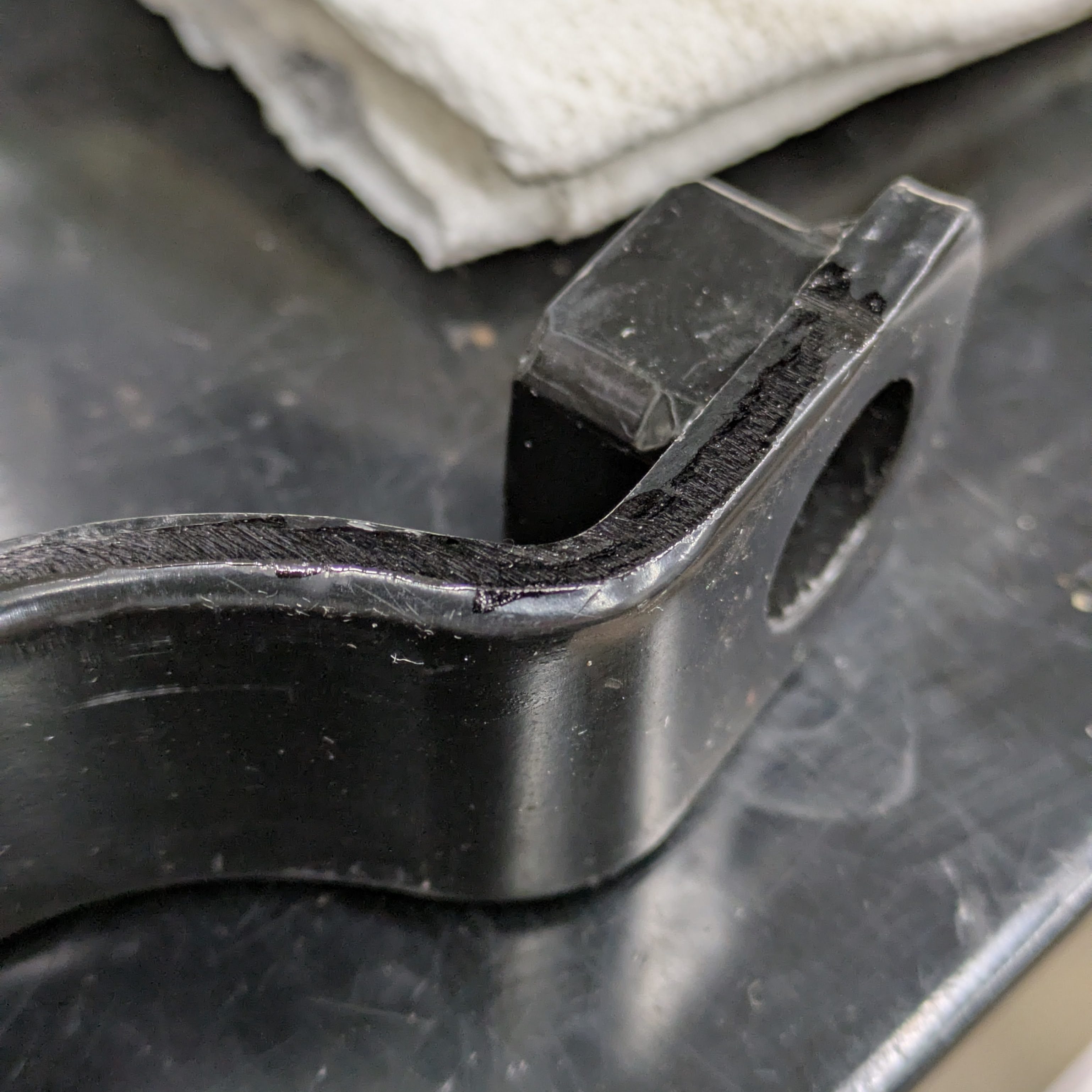
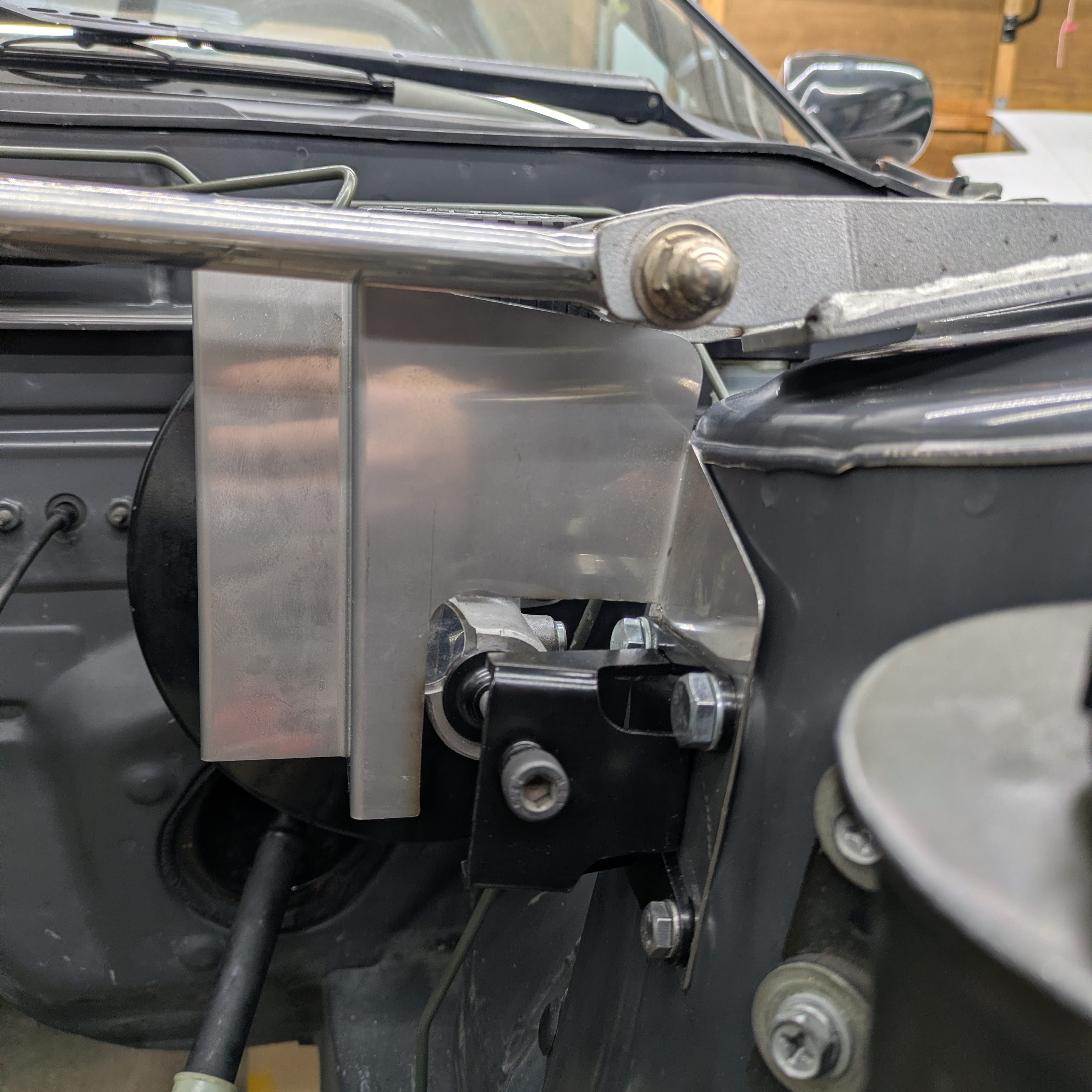
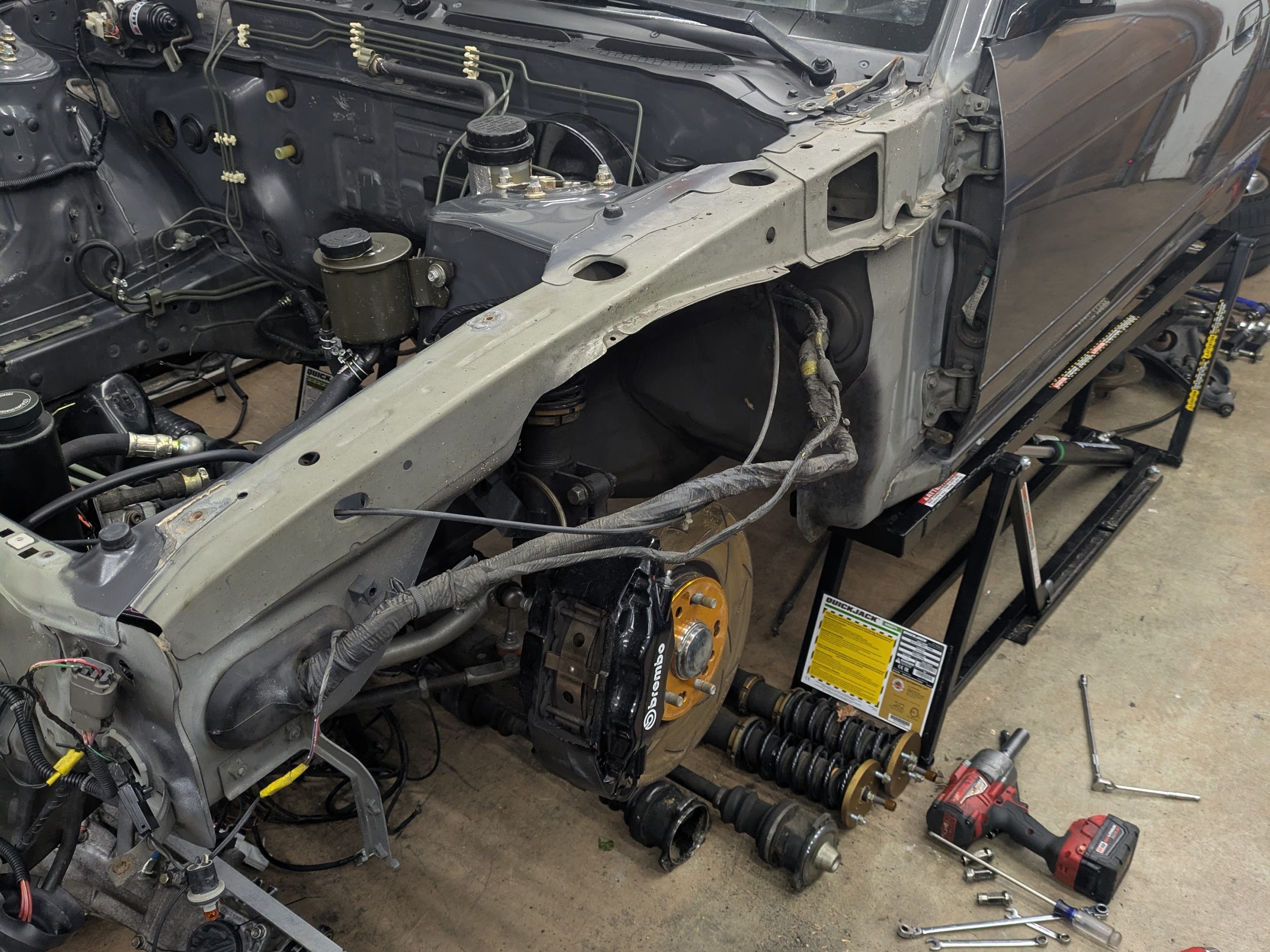
Moving on, and this is where we get into the weeds. I needed to add a brake master cylinder heat shield as they are known for transforming into a pile of plastic when exposed to a warm breeze. Even with my OEM manifold and heat shield, arriving at the end of a straightaway with nothing to slow you down isn’t an experience I desire to have. I purchased the Circuitsports heat shield as it is the go-to for protection and fitment. I tried the EnglishTuned one and it didn’t clear my brake lines and Z32 master cylinder. The Circuitsports did without modification, which was nice.
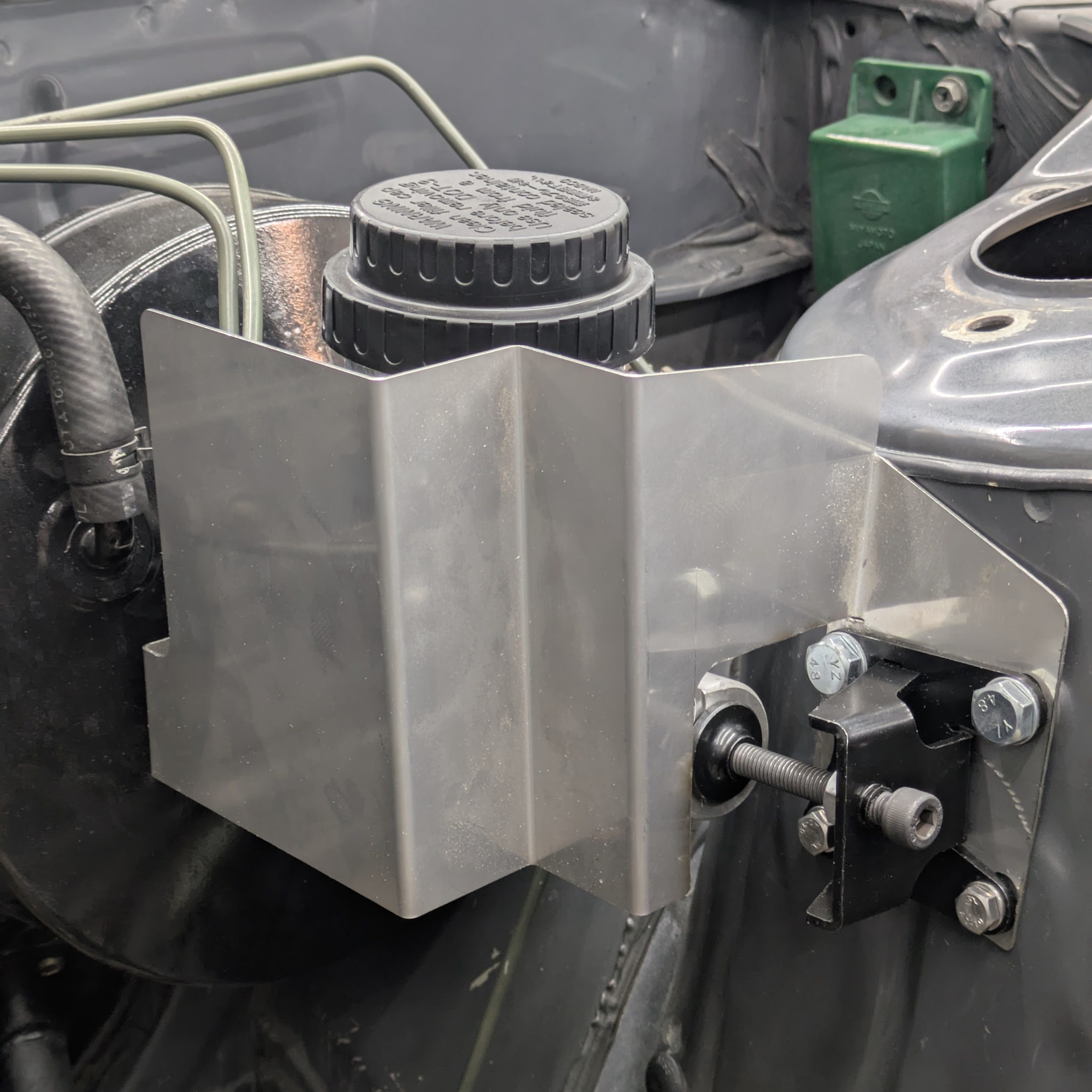
It may have cleared the factory components, but it didn’t clear the aftermarket components that I wanted to add. Once again, GKTech to the front of the class for the brake master cylinder stopper. I had one on my Miata, and I am fully supportive of them on 90s cars with a ton of firewall flex, especially with upgraded brakes that tend to be more sensitive. The consistency improvement is noticeable.
I ended up cutting a slot in the heat shield and bending it down flat as seen in the first photo. This allowed me to sandwich it completely between the brake master cylinder stopper and the strut tower so it is all very secure. I experimented with several different hole shapes and sizes, slowly trimming it throughout the course of the day, but I settled on the most serviceable and visually cleanest cut (to me). I’m not worried about heat intrusion from this angle, so it should be just fine.
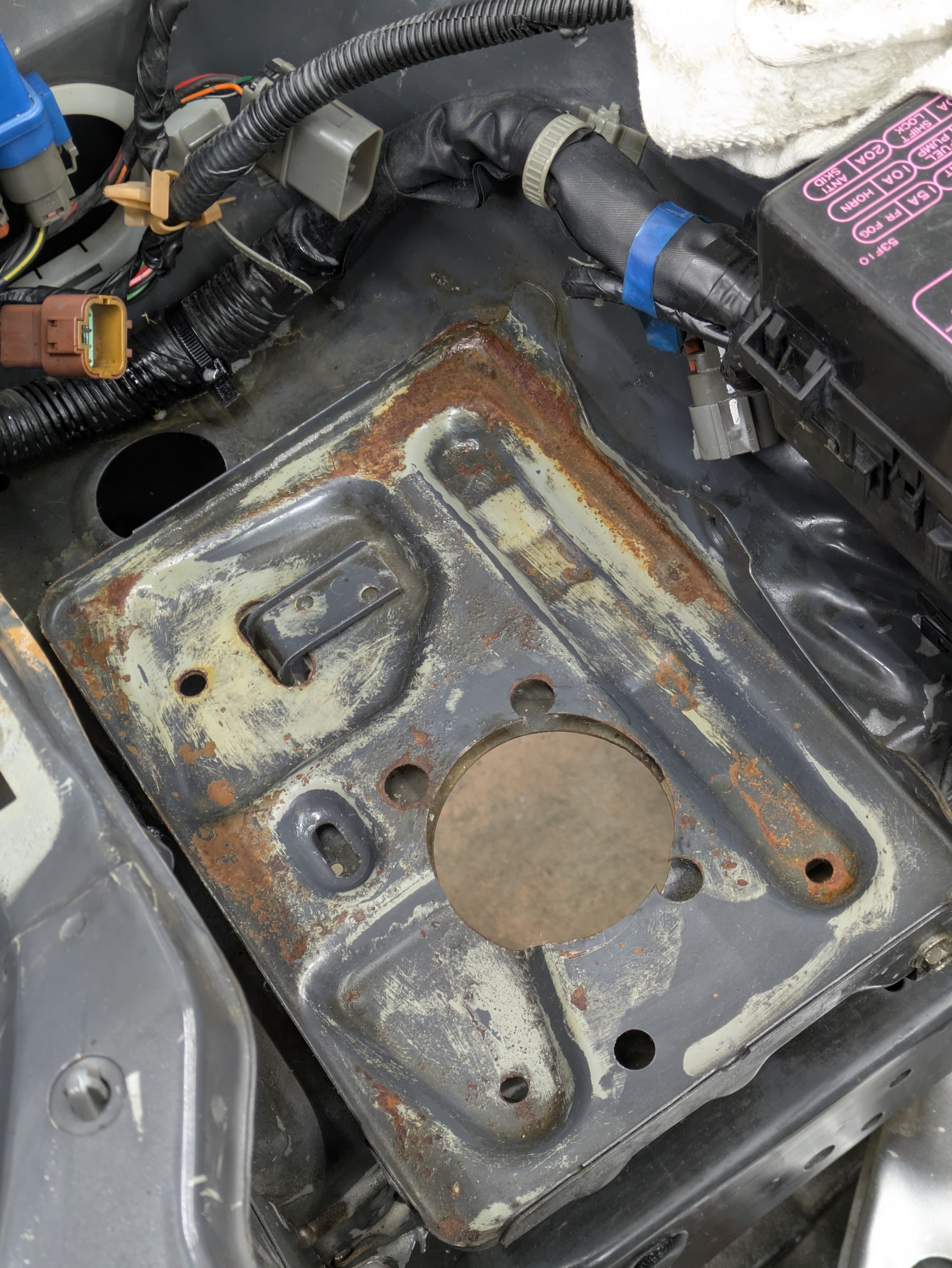
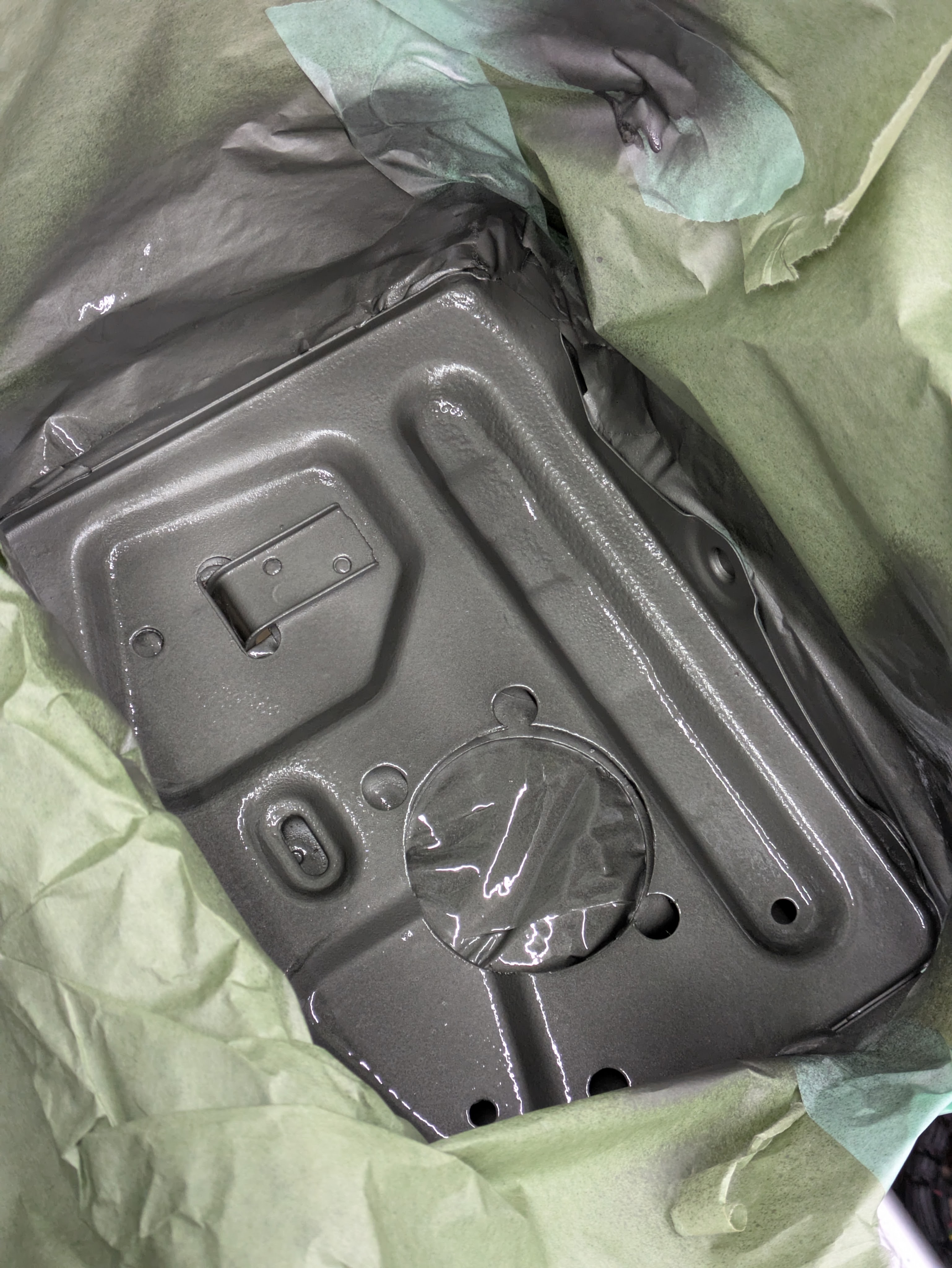
Another “it’s nice while the engine is out” task. East Coasters can stay mad that this is what my battery tray looks like. This was the most corrosion on the whole car.
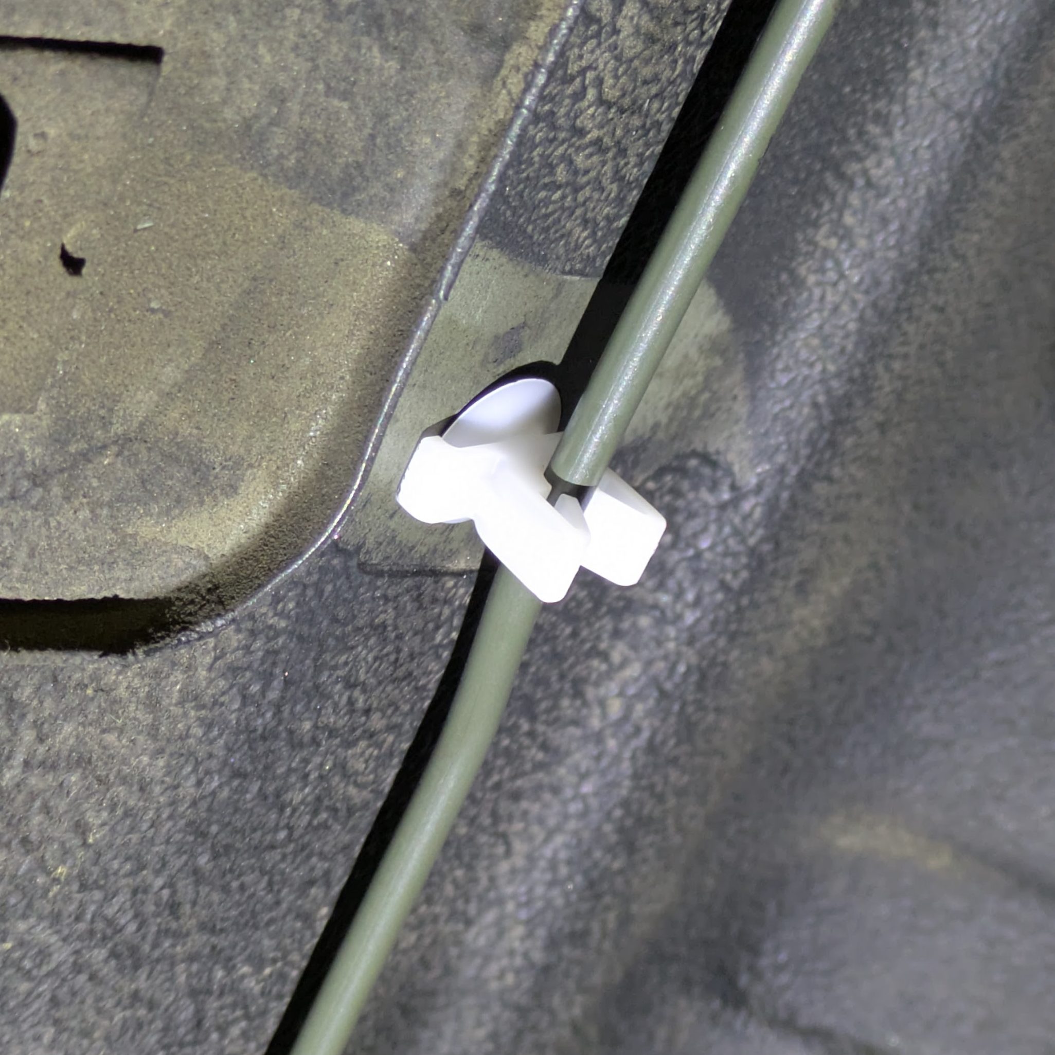
In an earlier post, I had noted how my chassis harness was still rubbing on the tire even after re-tucking it. I was able to exploit more length out of it by cutting the tape near the engine bay boot and pulling the whole harness back into the fender a few centimeters. With that extension, plus a new notch, I was able to get the harness out of harm’s way.

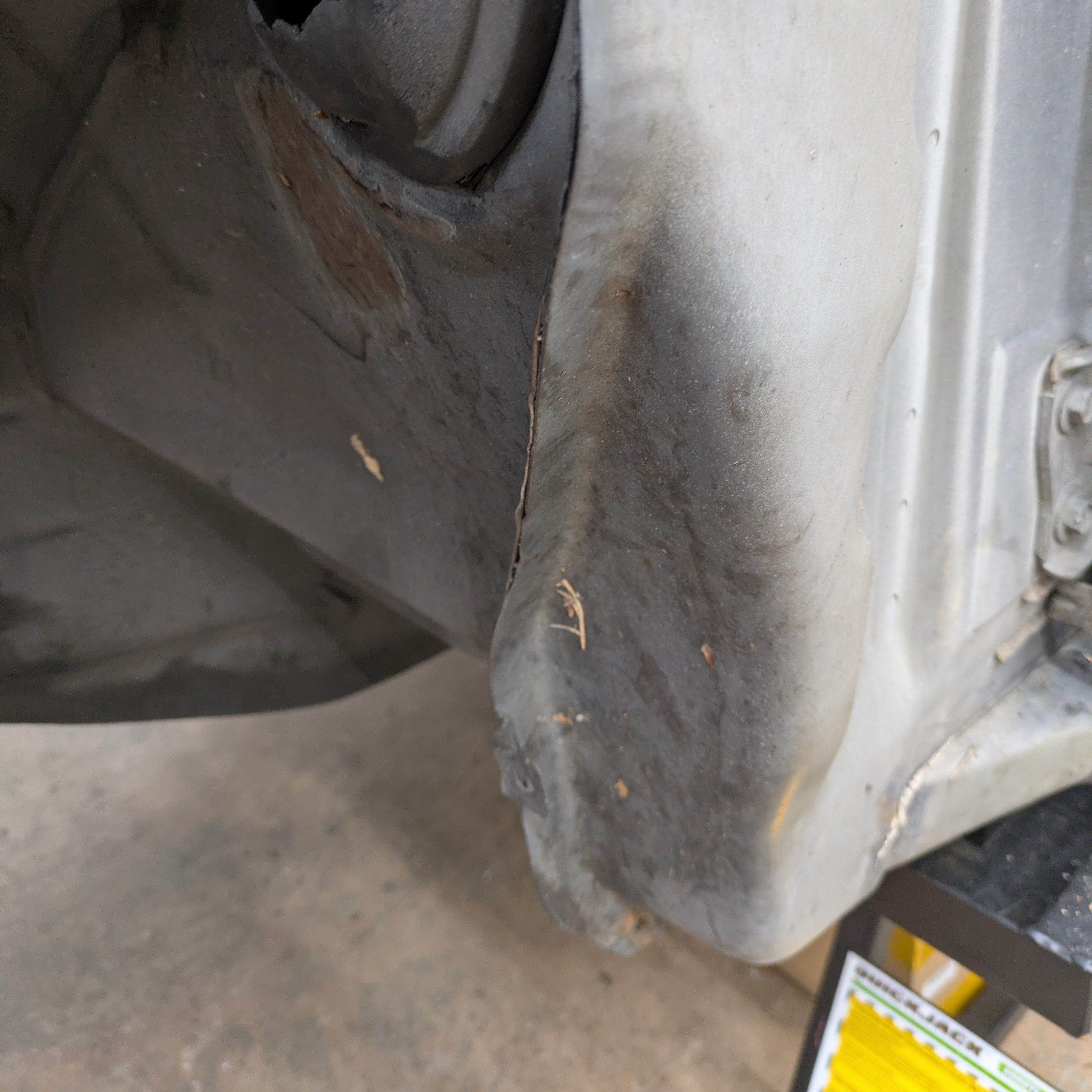
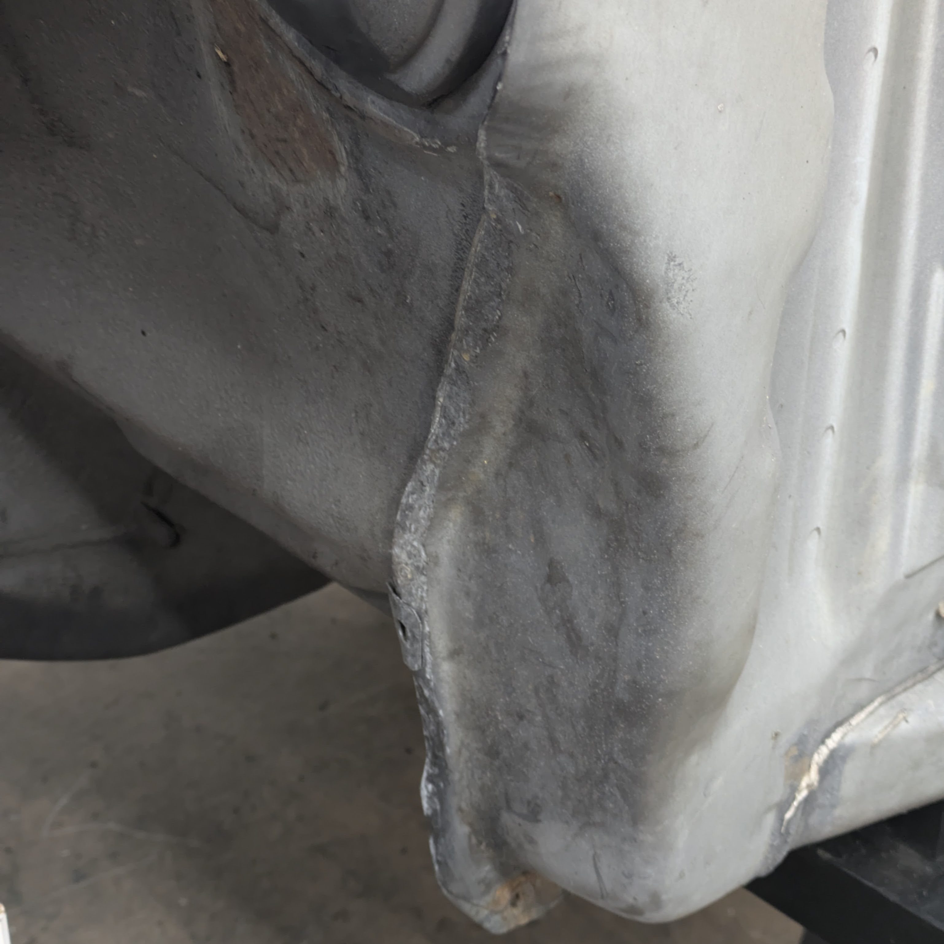
In a similar clearance conundrum, the seam that transitions from the upper rail to the pinch weld was still protruding on the driver’s side. This is an area where the tire can contact the body if left unattended, and it had only been addressed on the passenger side. I took the BFH to it, and after not a lot of effort, the problem was dealt with.
I intend to make carbon/kevlar/plastic fender liners for this car at some point to keep rocks out of the door seam and protect the intercooler plumbing, but that will have to wait for a later time.
Moving to the back of the car, and after all of the extensive subframe work that had been done in the last post, I knew it would be a crime to install a freshly powdercoated subframe next to 30 years of grease and grime.
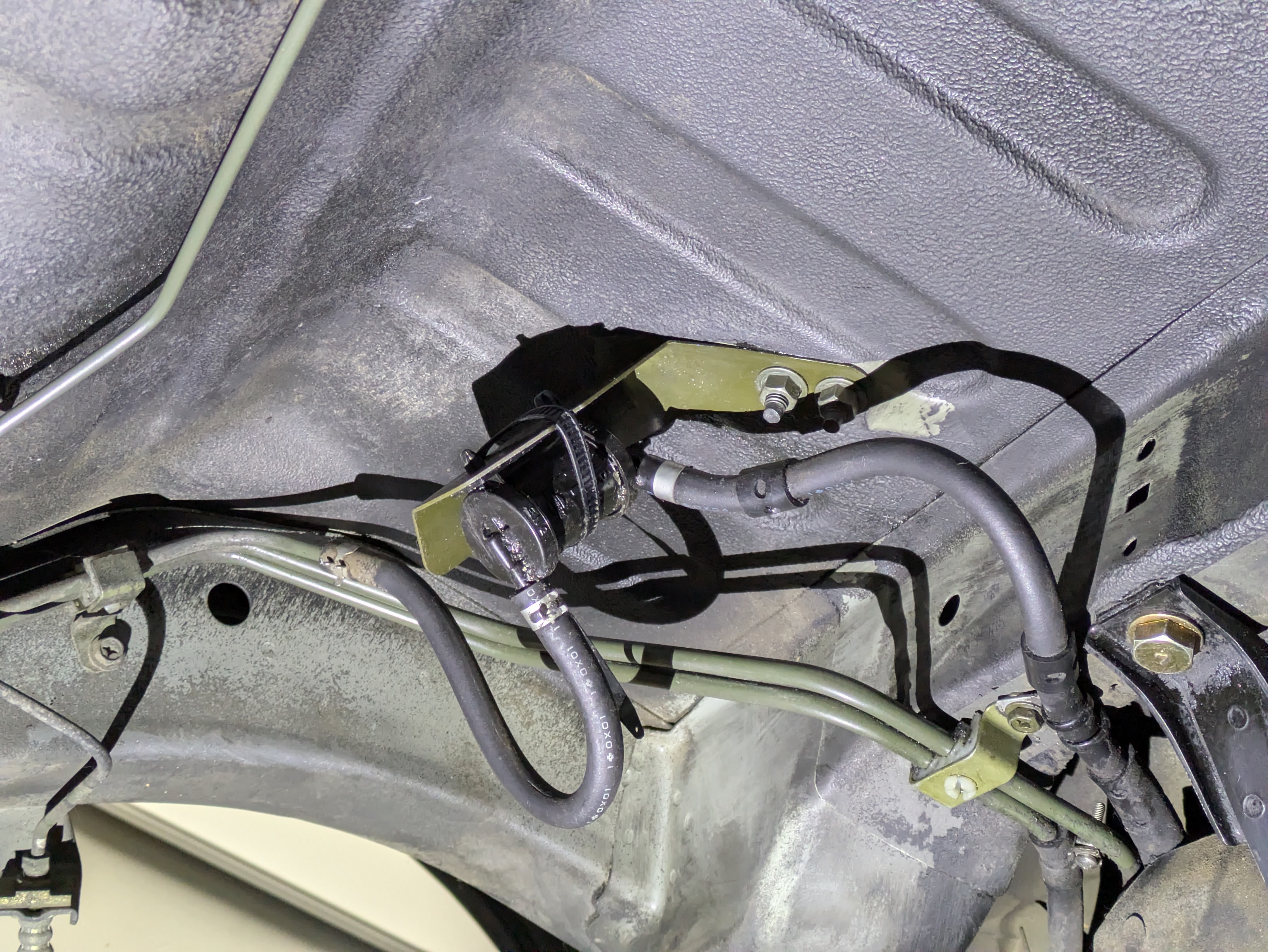
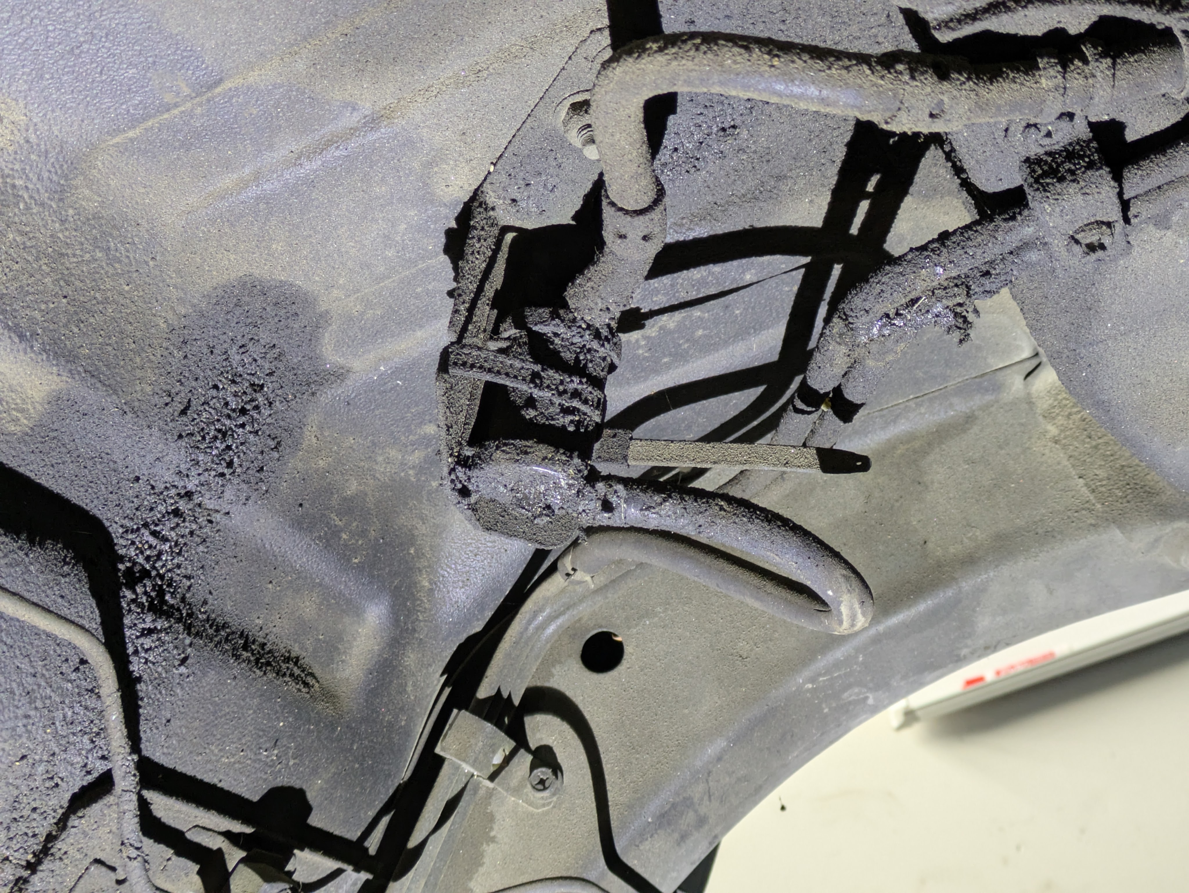
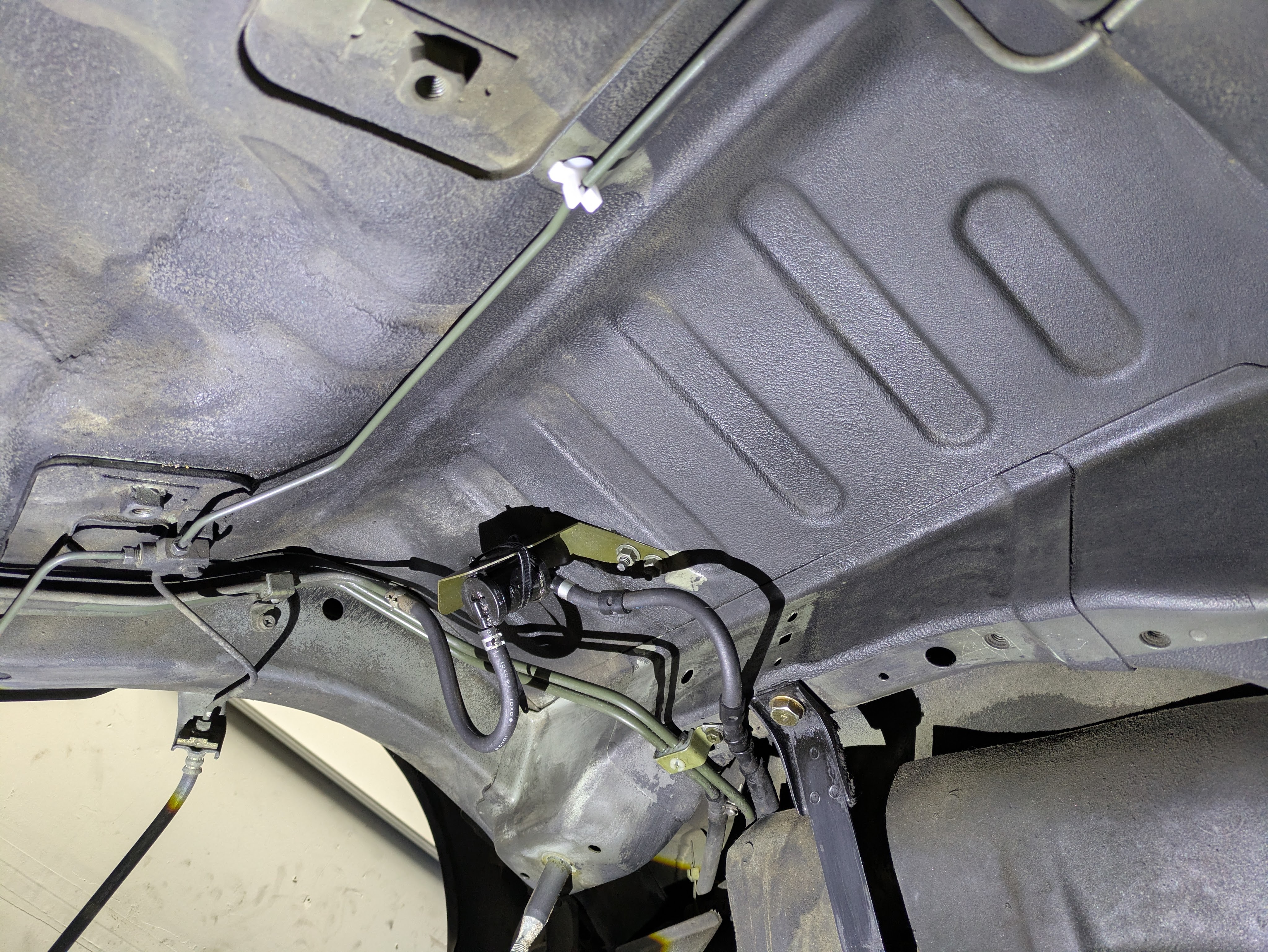
After huffing fumes and taking a bath in kerosene, you can now actually see the evap components that reside above the subframe. I wasn’t going for perfection, but this is a vast improvement.
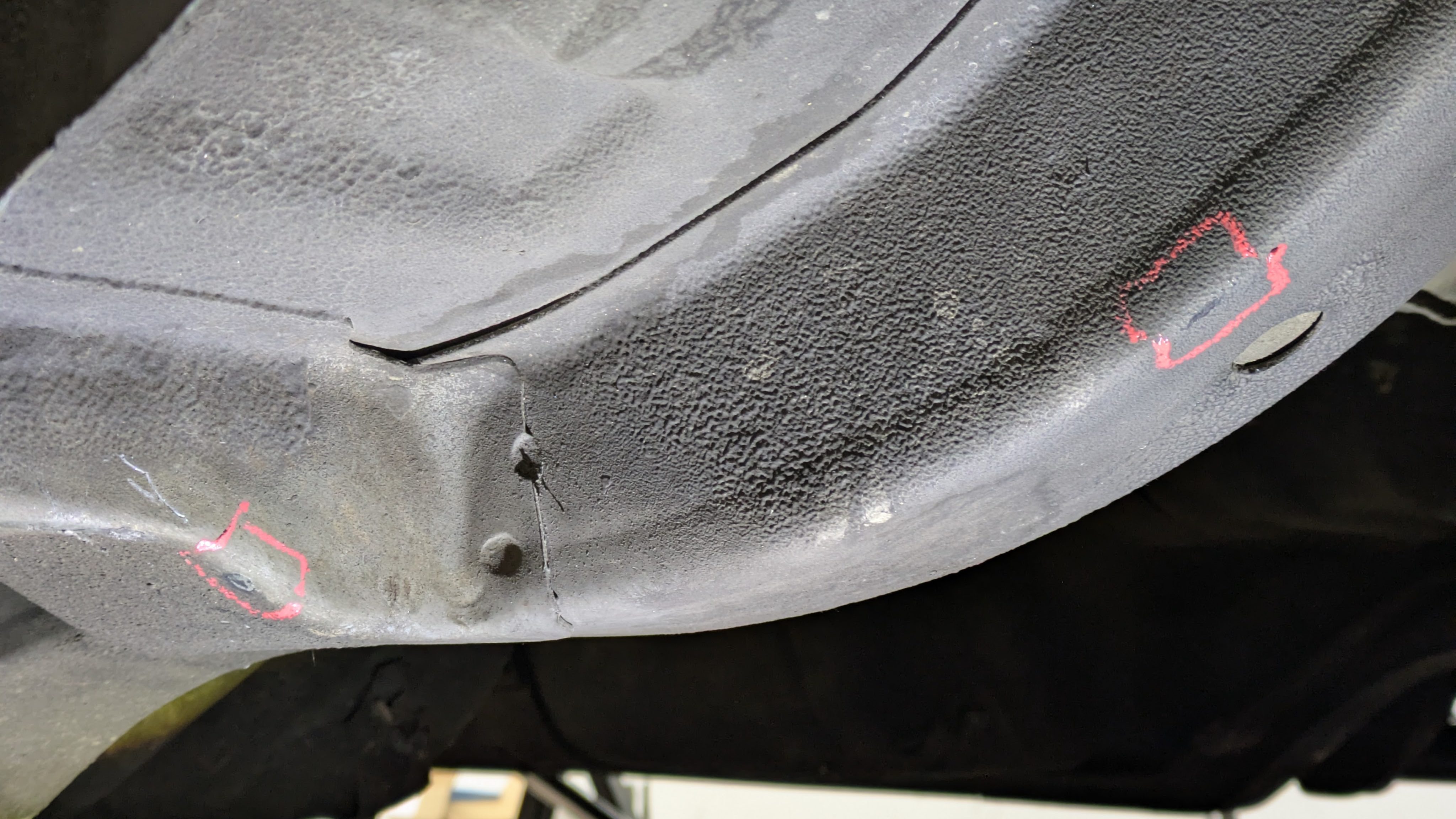
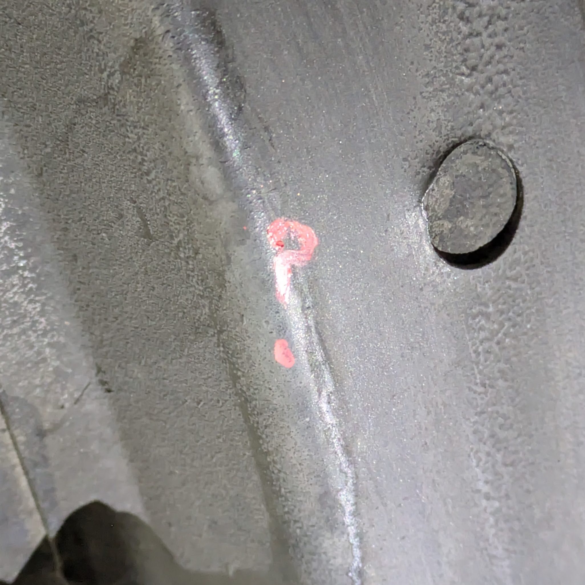
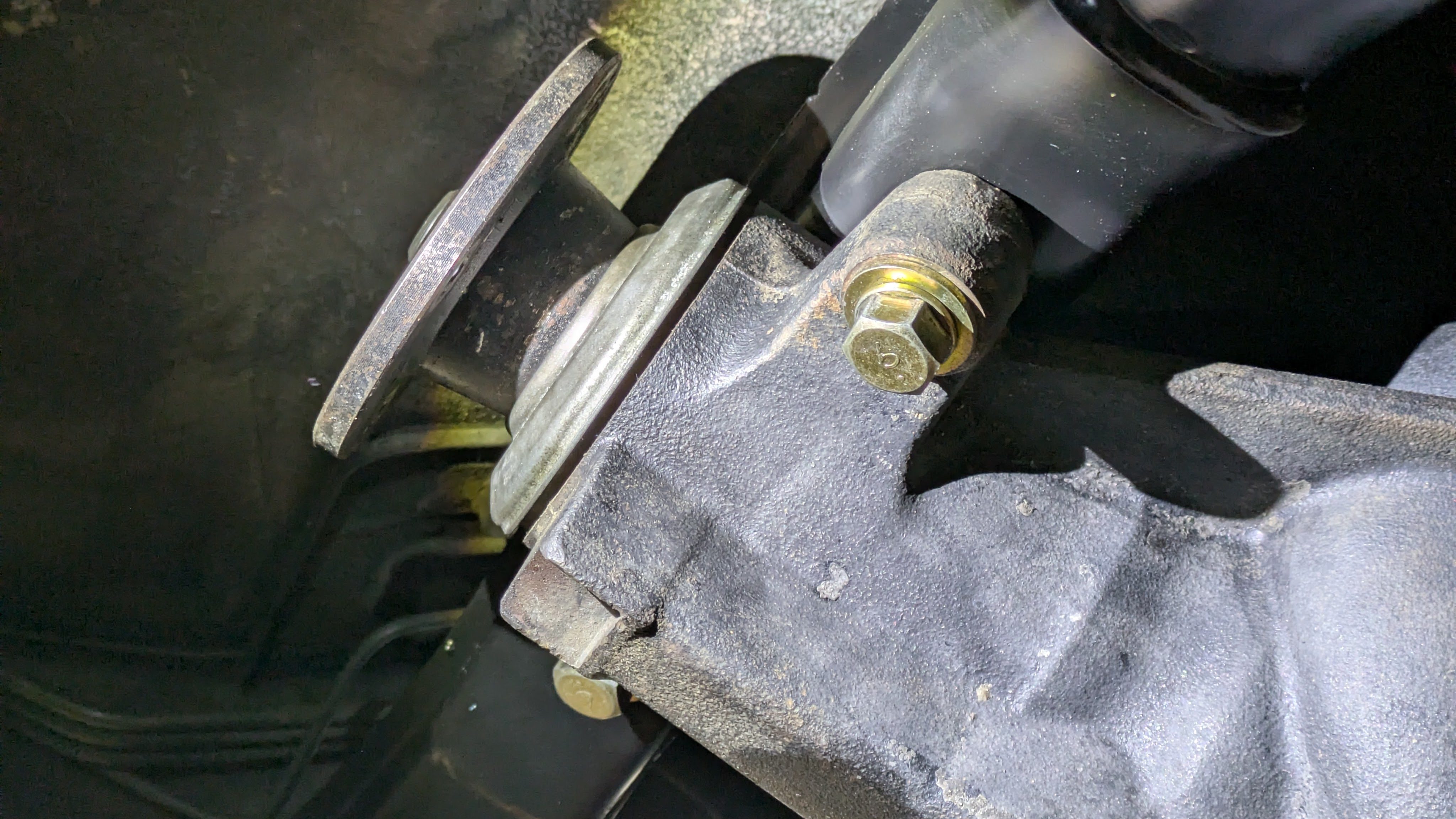
After prepping the area for the subframe install, I noticed some areas where the subframe was contacting the body. This is due to the 15mm overall height increase from the subframe bushings which place the subframe directly against the body. I began marking out the areas that needed clearance, and as I was doing so,
I had another one of those “this is yours now, you’ve ruined it” moments during this and the seam clearance in the front, similar to blasting holes in the floor for the harnesses. I usually shy away from irreversible mods, especially like clearance of structural members, but I want it to be right, and it’s not like it didn’t come to me with dents and holes in it. This is a car that’s built to be enjoyed, and sometimes you have to some irreversible stuff to make that happen. One of those strange internal struggles I have I guess.
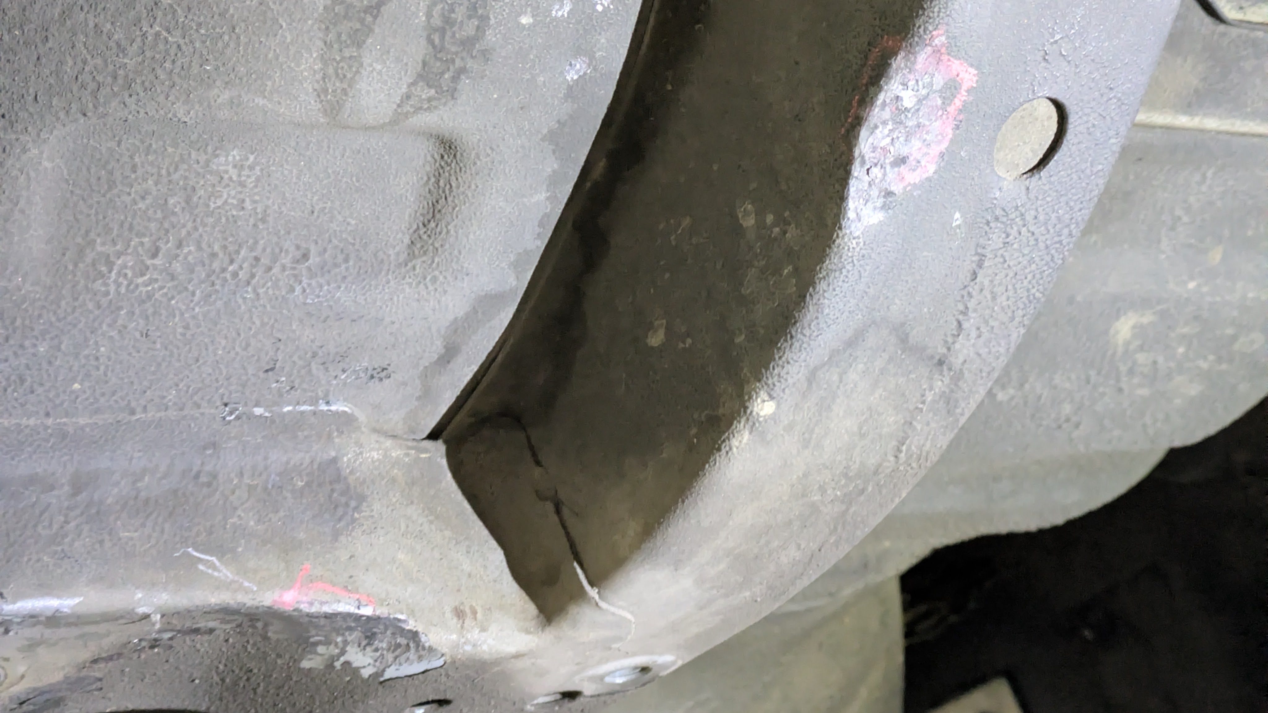
So anyway I got over that pretty quickly and started wailing on it with a BFH.
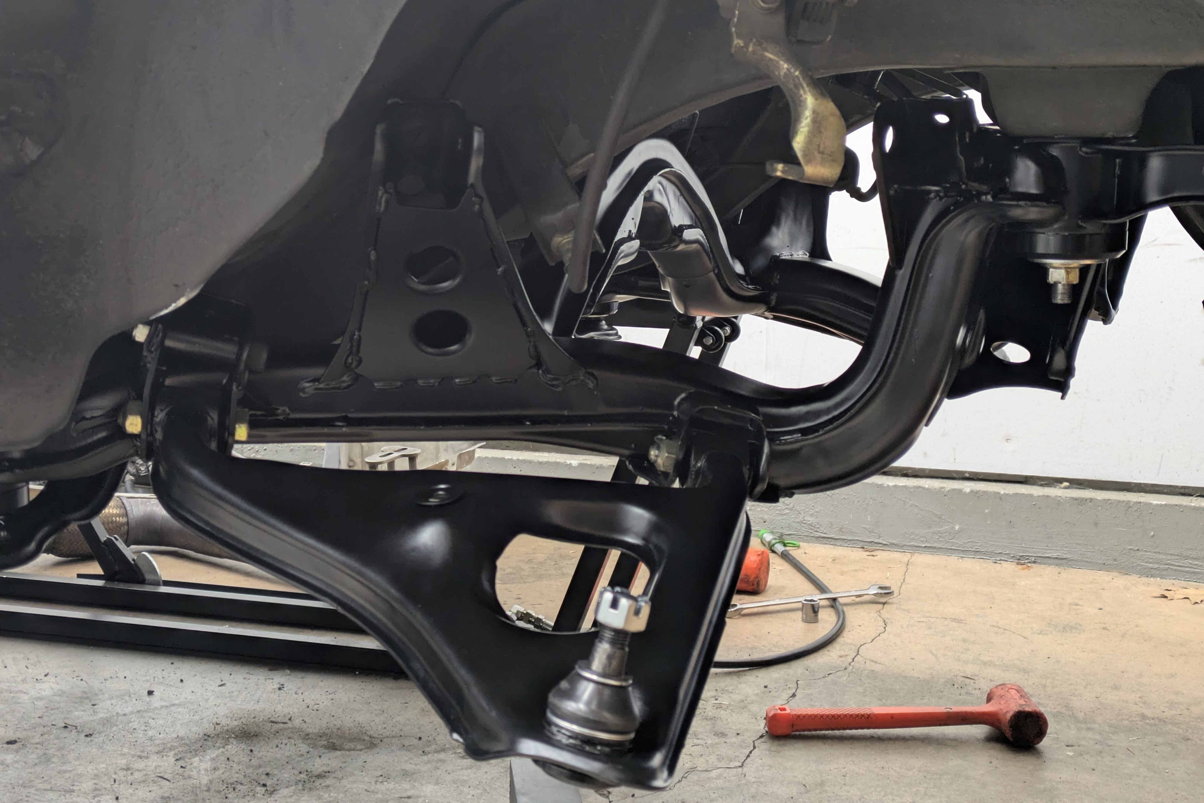
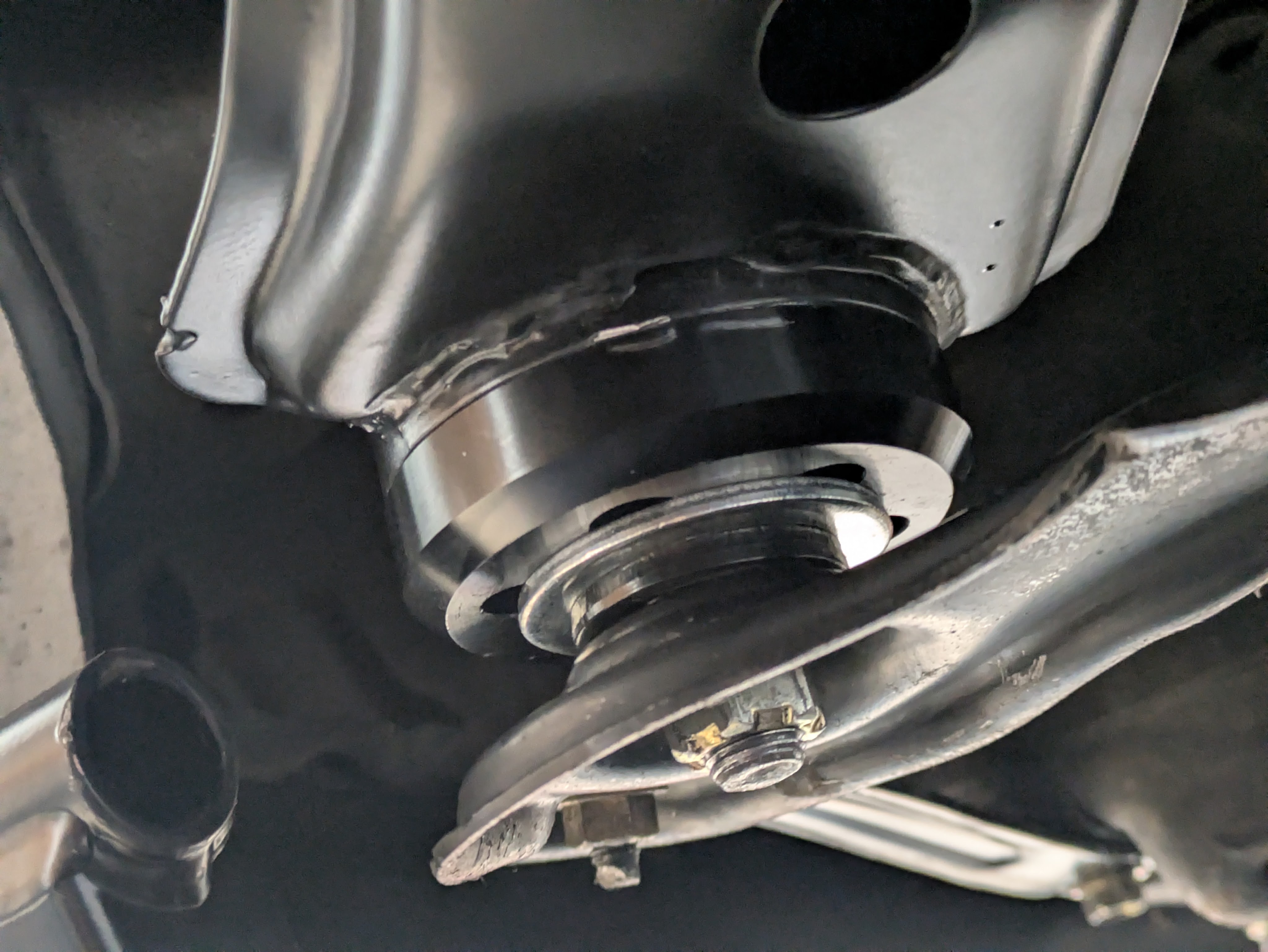
With the power of editing, the subframe is now installed. This was greatly abbreviated, as it took 4 installs and removals to get it all right. I even had to clearance the trans tunnel under the rear seats where the front diff mounts are. While no easy task, Lucas and I got really good at smacking this subframe into place. I guess it is now one large chassis brace to square the whole back end of the car up.
I also installed the RLCAs, which was primarily an exercise in how many times I can hit my hand with a hammer before I give up for the day. The sphericals were no easy thing to align, however after all the other work I did before powedercoat, it went significantly easier as the arms were already the right width. It was definitely a relief when all the arm bolts were in and torqued, including the upper bolts in what would be the original arm mount location to act as reinforcement. I was even able to wrestle the retaining rings back on to the ball joint boots, which was a nice small win.
And with that, I had a canvas to start consolidating the gigantic pile of parts that lay about my garage and house. This plus the motor install were the inflection point in the “parts going back on instead of coming off” part of the build.
Clean parts are a lot more motivating than dirty ones, and with the temperature average increasing by the week, it’s time to hammer down so I can drive this thing this summer. It’s been difficult to take a break from working on the car to write about it because the progress has been extremely motivating. I will make the time though. I have a lot of cool things to share.
Until next time.
