
Forward: There is a lot of bouncing between projects in this post, mainly because 10 different things were occurring at once, and this is just how they shook out. So fair warning, its a bit all over the place, but the end result is worth it.
If I could have my cake and eat it too, the engine in my track car would be simple, durable, and reliable, all overlapping to form the Venn diagram of being effortless to both use and maintain. OEM engines in OEM trim (for the most part) do a spectacular job of this, and while I would like to think that I can do a few things better than the OEM given the evolution of technology and materials, the vast majority of strategies and solutions will be delegated to those with millions of dollars of funding and thousands of years of collective experience.
When distilled to it’s essence, every single challenge in motorsport has to with heat management and mitigation. With a turbo car on a road course, this becomes even more vital, and it is why I generally advise against forced induction on track at all. I’ve obviously chosen the hard path, but what else is new?
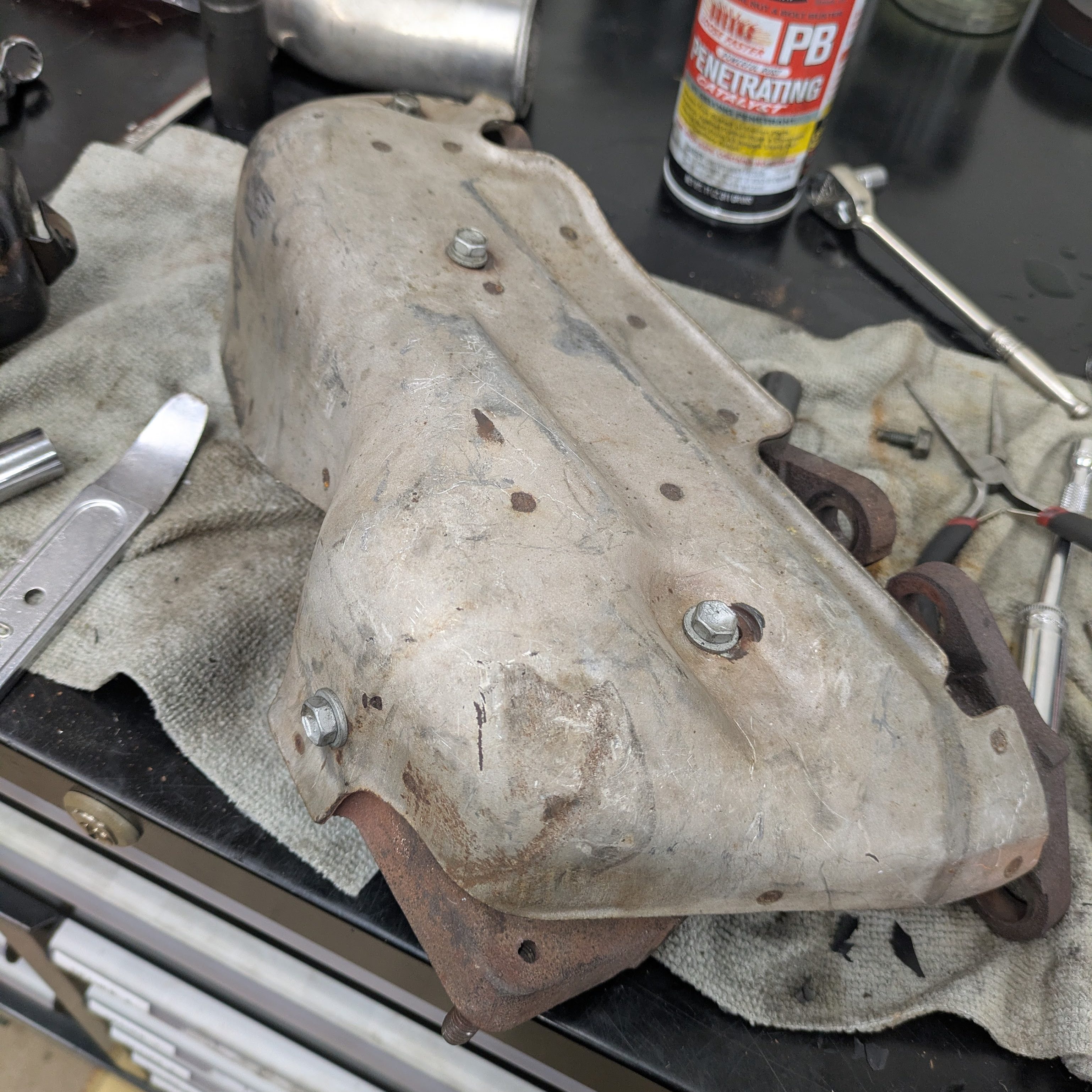
The reason for my return to an OEM exhaust manifold on this car was so that I could run an OEM heat shield to attempt to keep everything surrounding it alive, while retaining the factory air/oil separator tank often discarded when a bundle of snakes find their way on to SR20s.
I was able to pick up an OEM S13 heatshield in great shape minus one wallered out hole, and as predicted, the fit was perfect. I then sent the heatshield out for Jet Hot Coating for both aesthetics and to be a more effective heat barrier. I debated the entire manifold, but this was on an evaluation basis due to the cost. If it needs it, it’ll get it, but the heat shield is doing the heavy lifting.
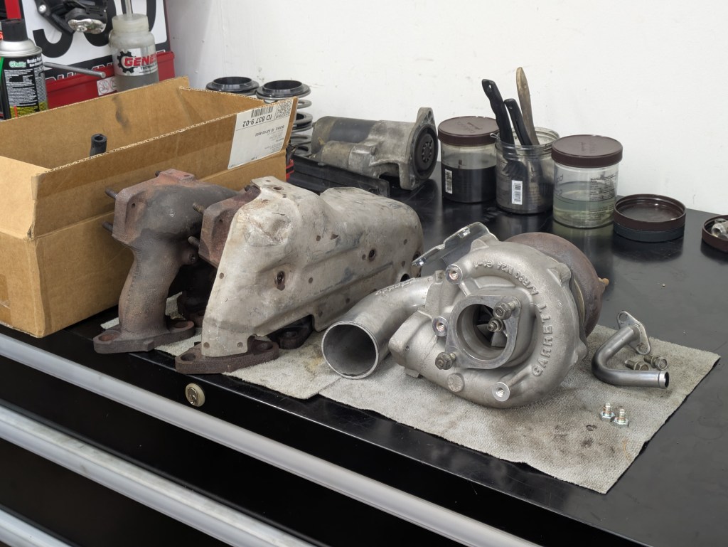
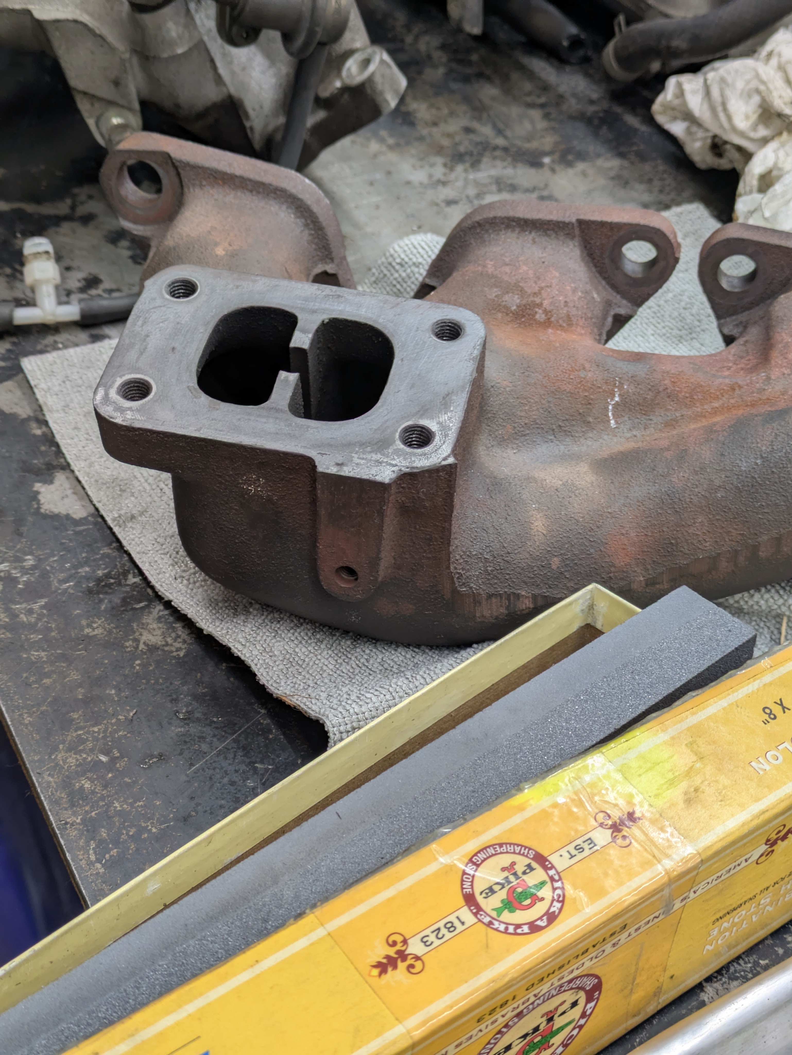
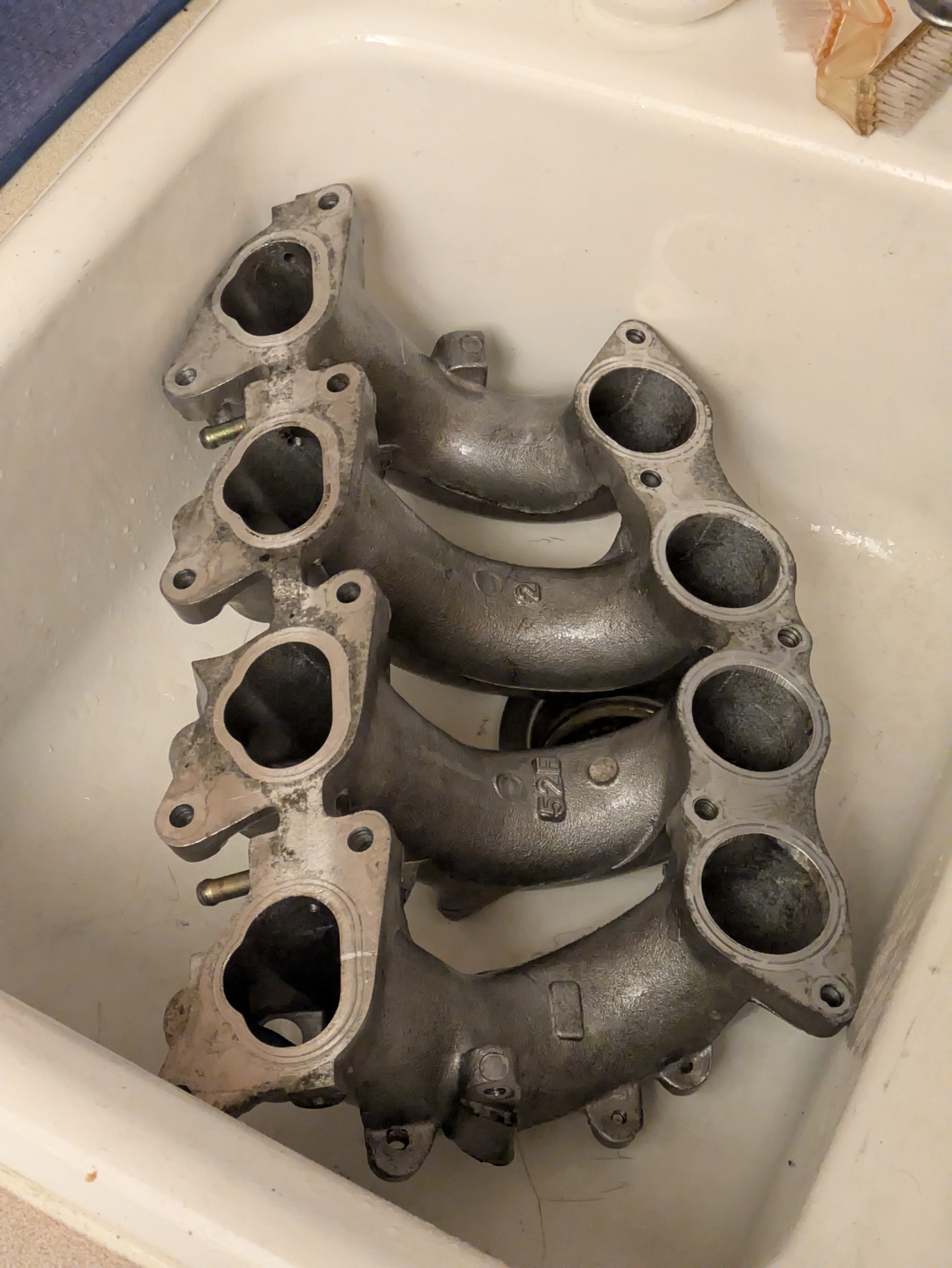
I had two options when it came to OEM manifolds: the manifold that came off of Luis’s motor, and the manifold that was included with my car when I purchased it. The manifold from my car had very few miles on it compared to Luis’s, so for crack potential mitigation, I selected the one original to my old motor.
Quick aside to discuss the turbo: early on, far before the built motor came into play, I made the very intentional decision that this car was going to remain OEM S15 T28 for the foreseeable future. While it is not a powerhouse of a turbo, and the motor can handle far more, the fitment, integration, and ever-long durability of these turbos is not to be discounted. While I will be sacrificing some top end power on track, I make up for it in mid range torque and the ability to actually spool the turbo at autoX and out of slower corners. Maybe at some point in the future, a GT28XX frame Garrett may find it’s way onto this manifold, but I want to drive and experience a T28 for a good long while before I stray from what the factory intended.
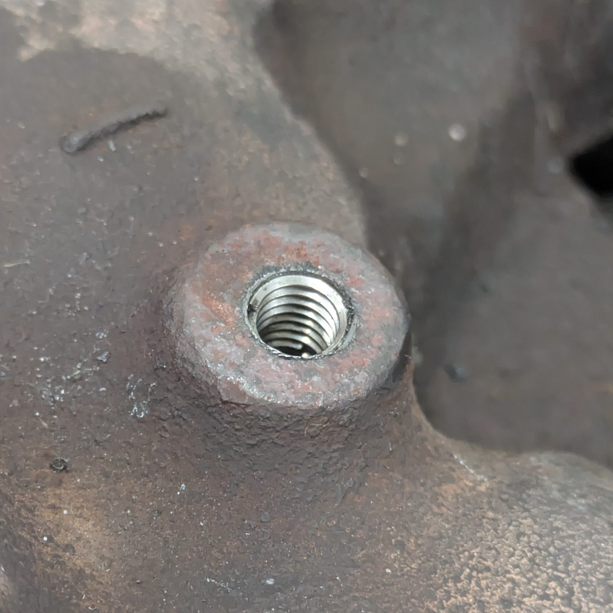
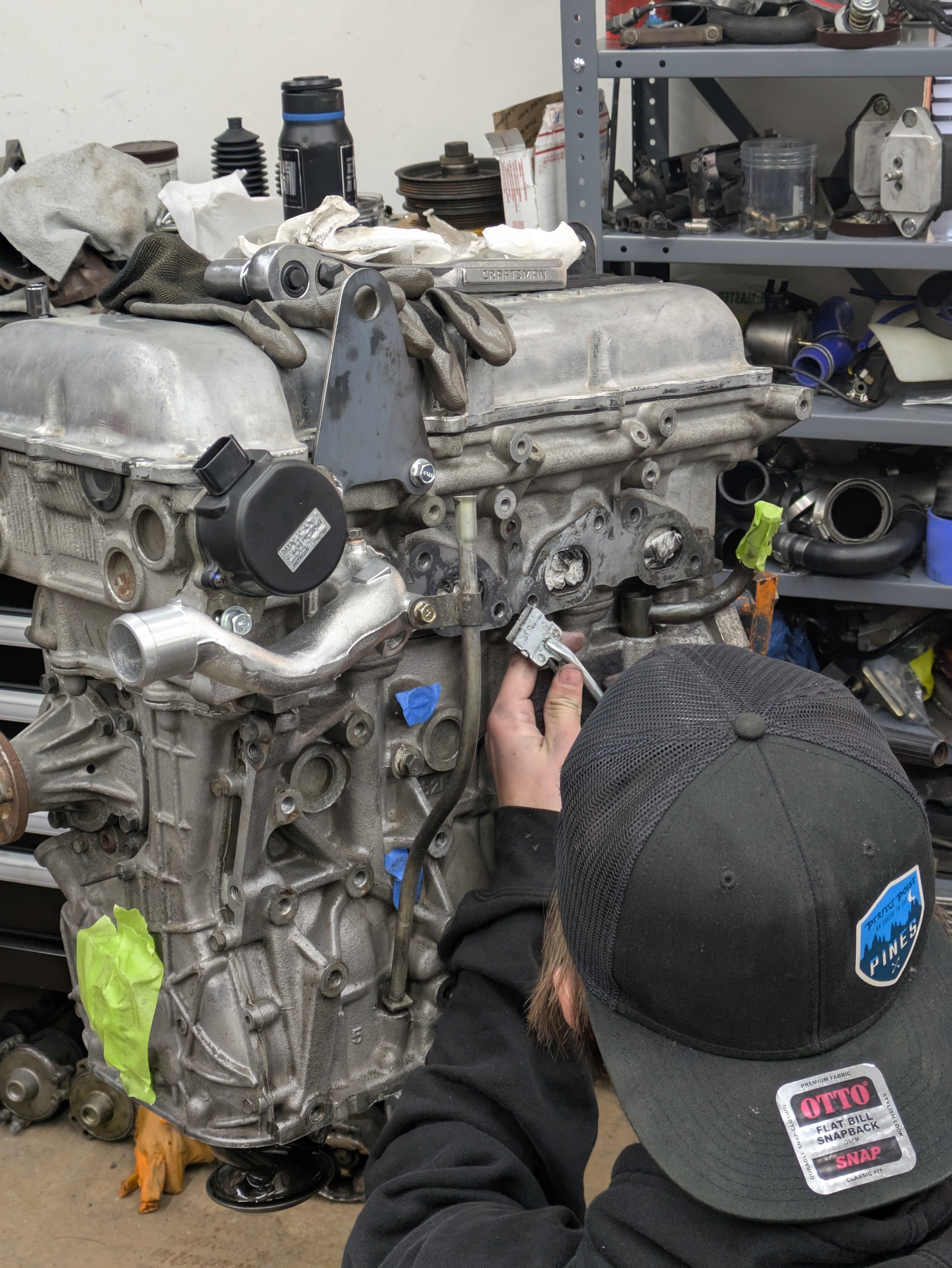
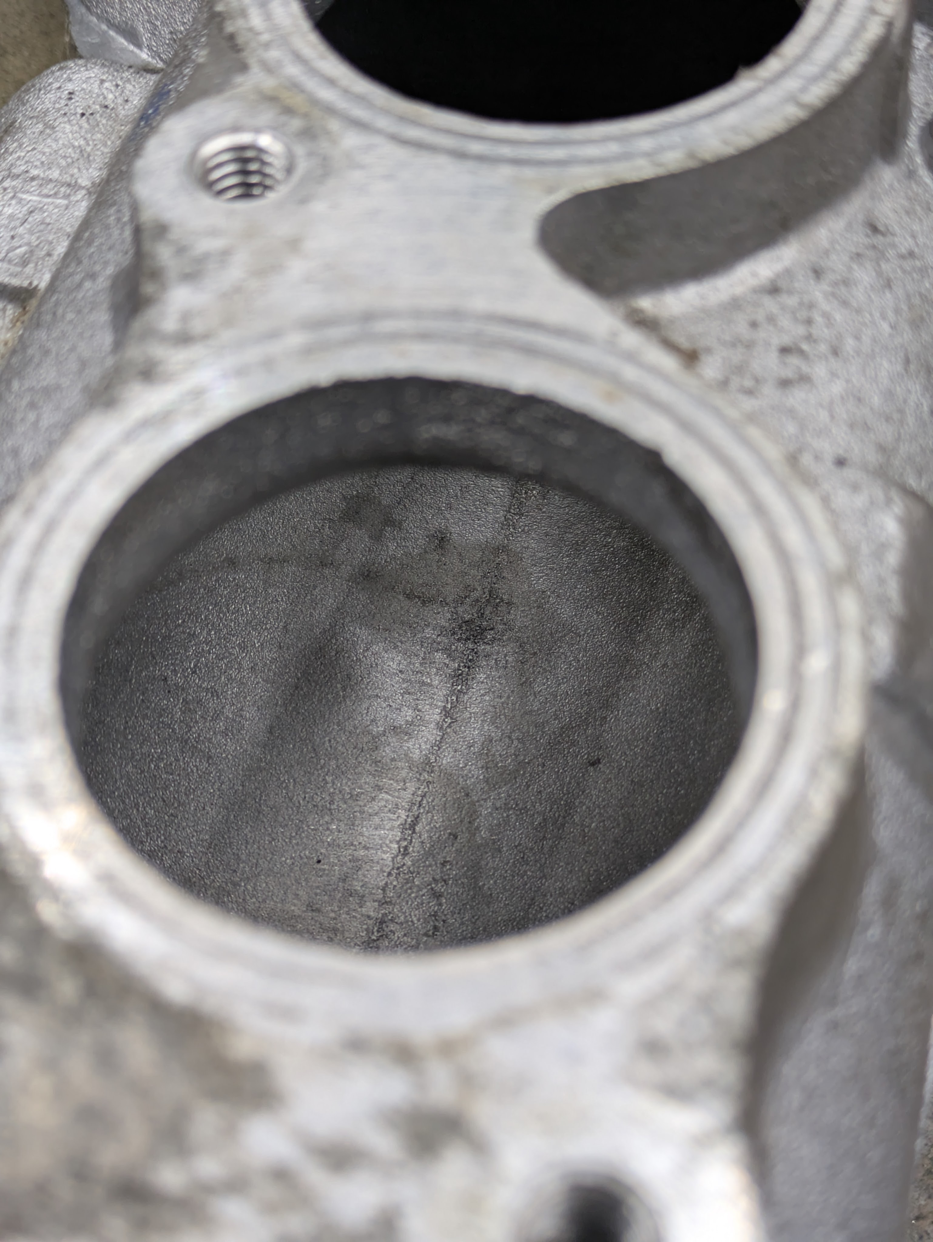
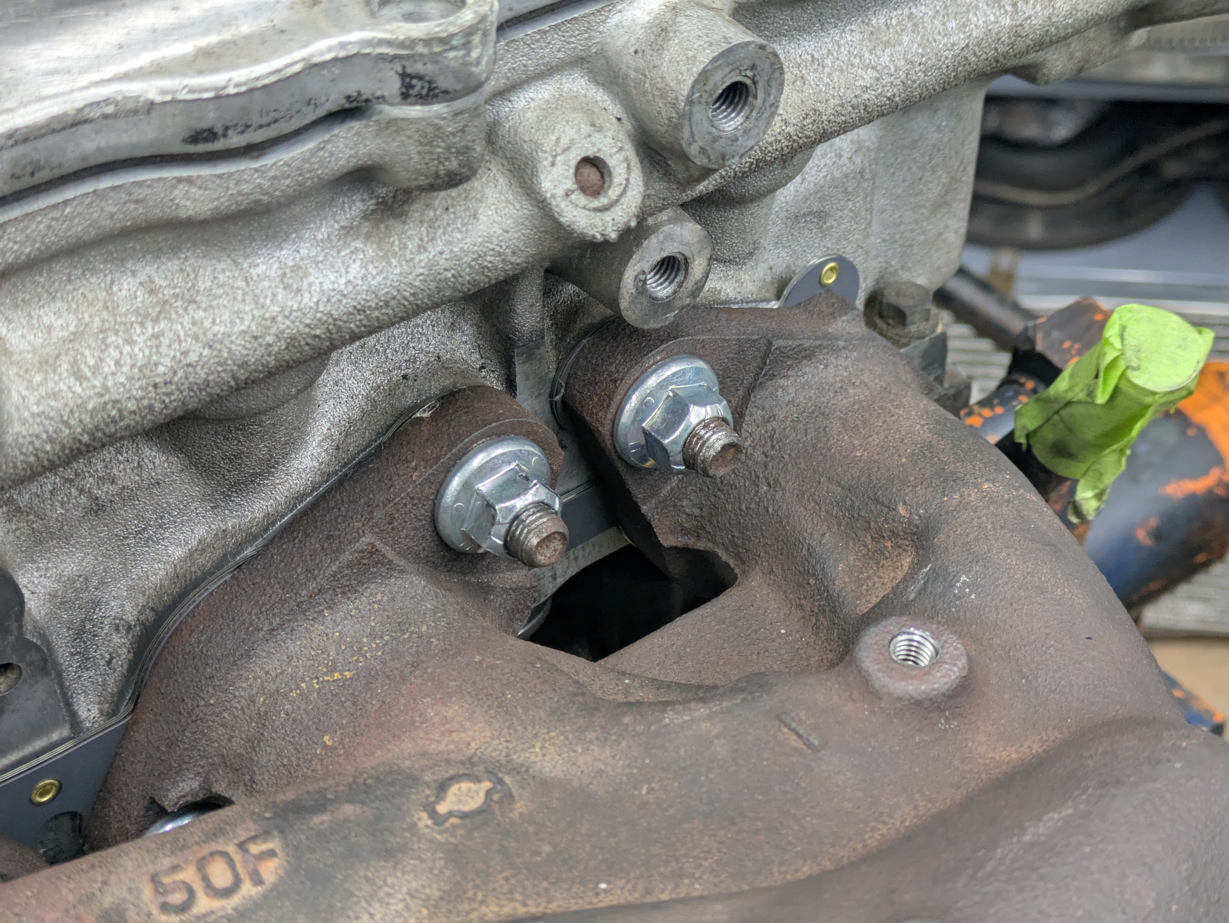
Circling back around, unfortunately my manifold came with a treat in the form of a broken off bolt. While I would have loved to Time-sert this, a helicoil will do the job fine, is cheaper, and what I had on hand.
Both manifolds also had significant pitting from corrosion on the main mating flange between the manifold in the cylinder head, so after fixing and test fitting the manifold, I dropped it off at a local automotive machine shop to have it resurfaced. This was better fenced to professionals that actually have the fixturing to perform this job rather than me fumbling around with it on one of our mils. They ended up taking 0.020″ off to return it back to factory spec. It was money well spent, and I made some friends along the way., so no complaints from me.
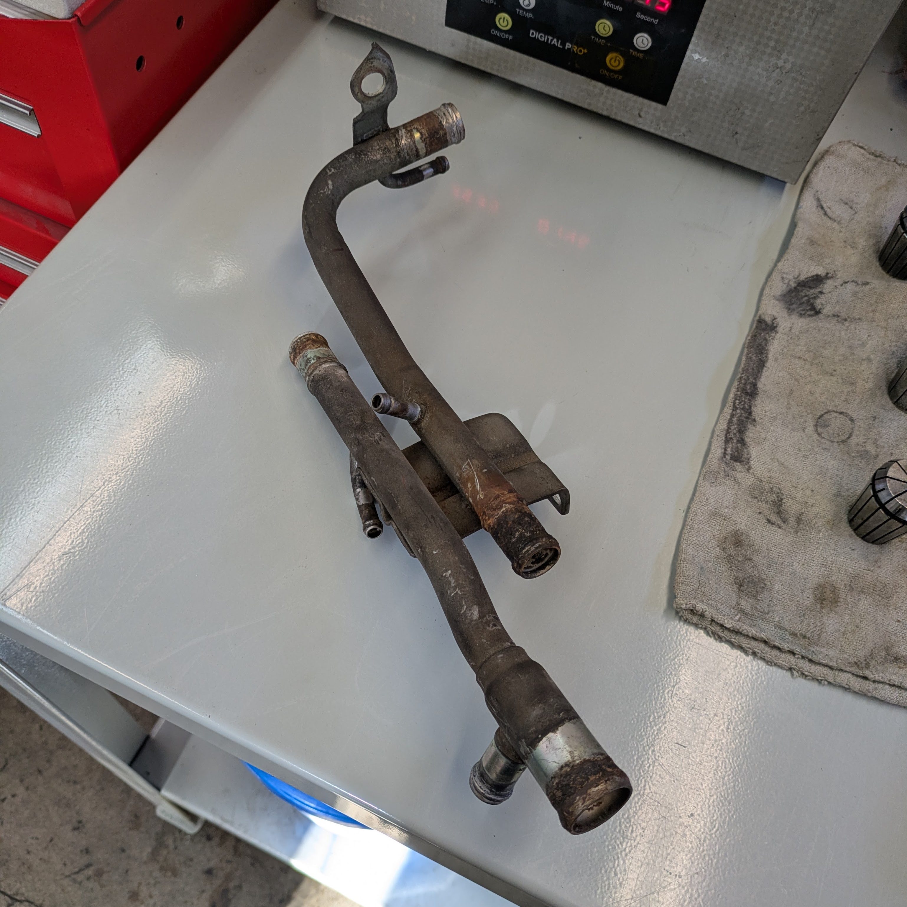
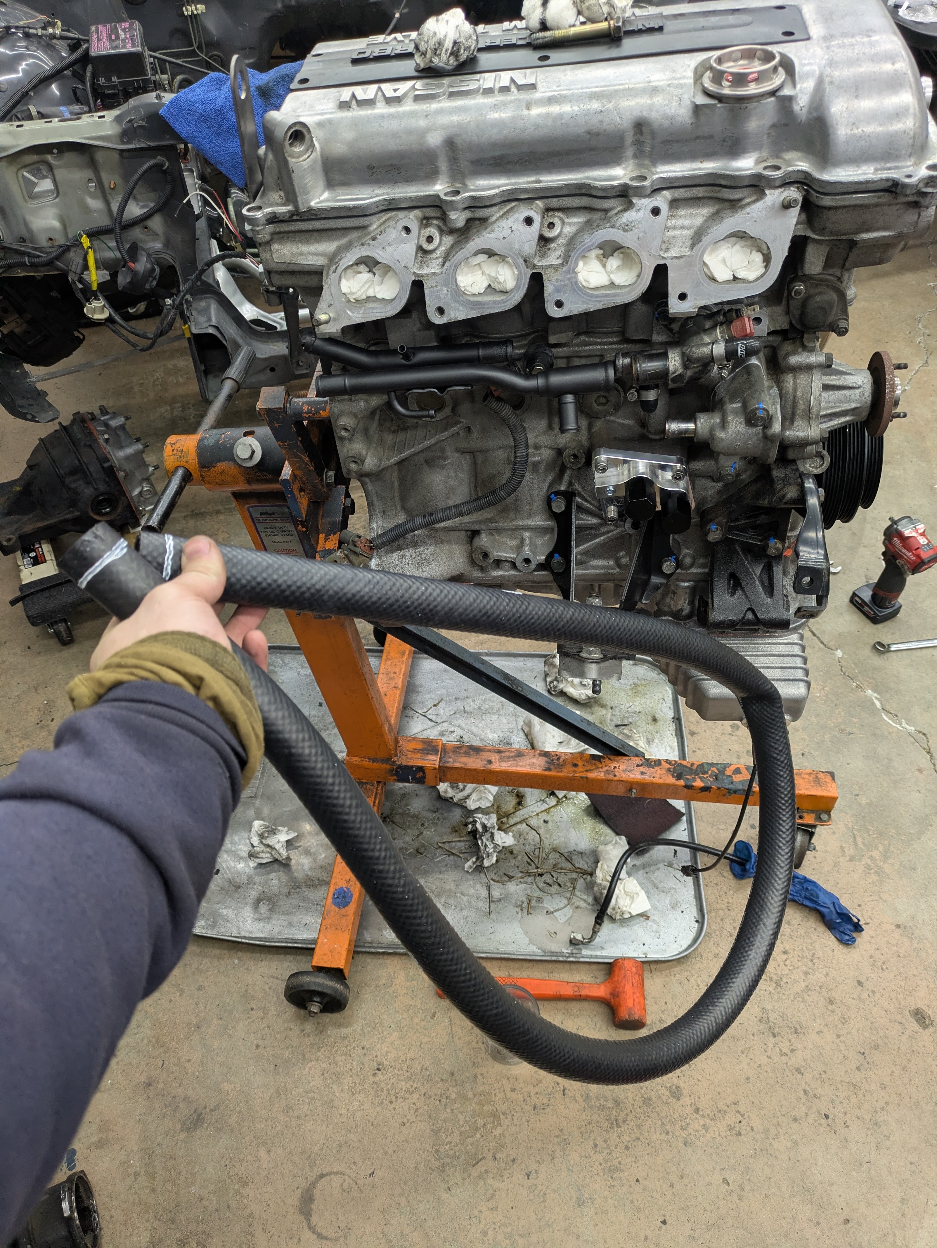
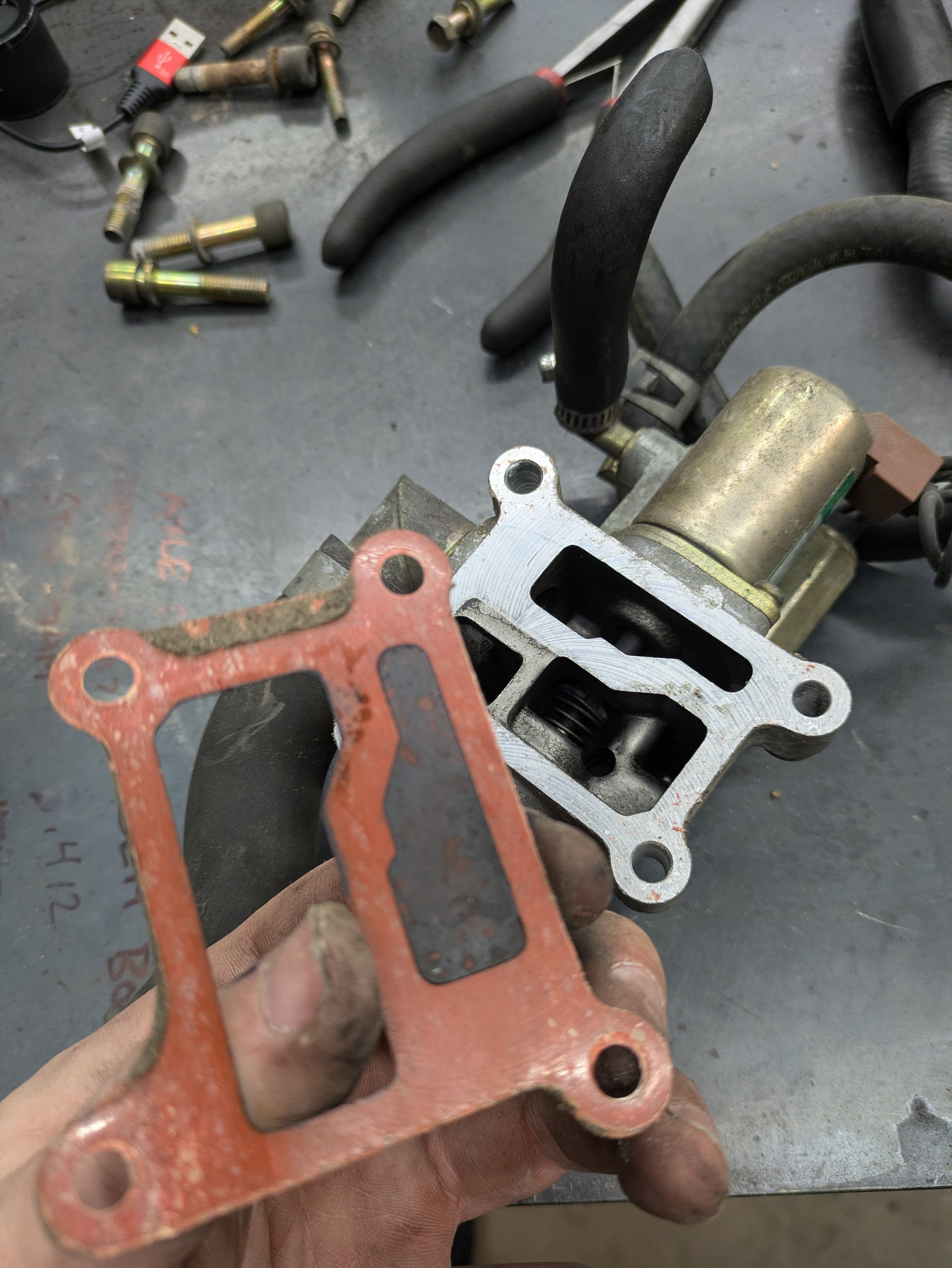
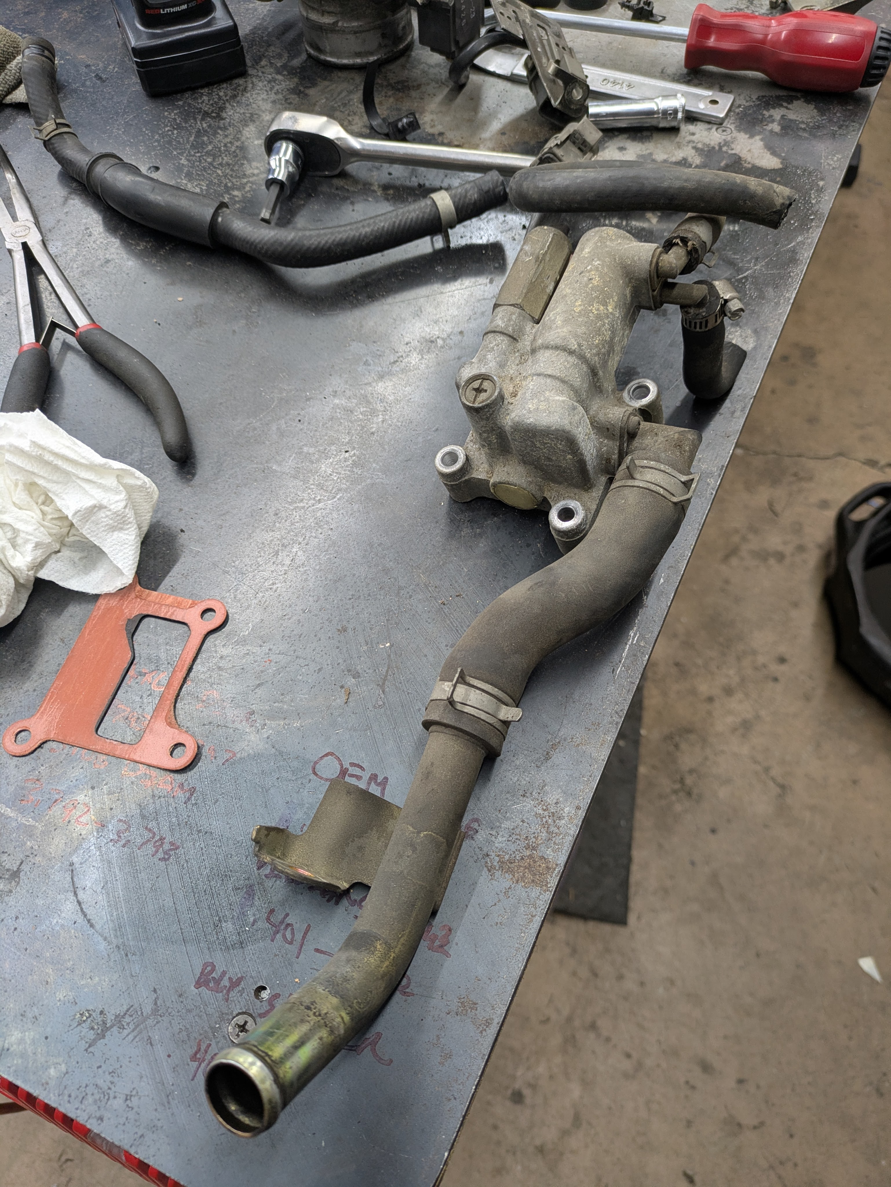
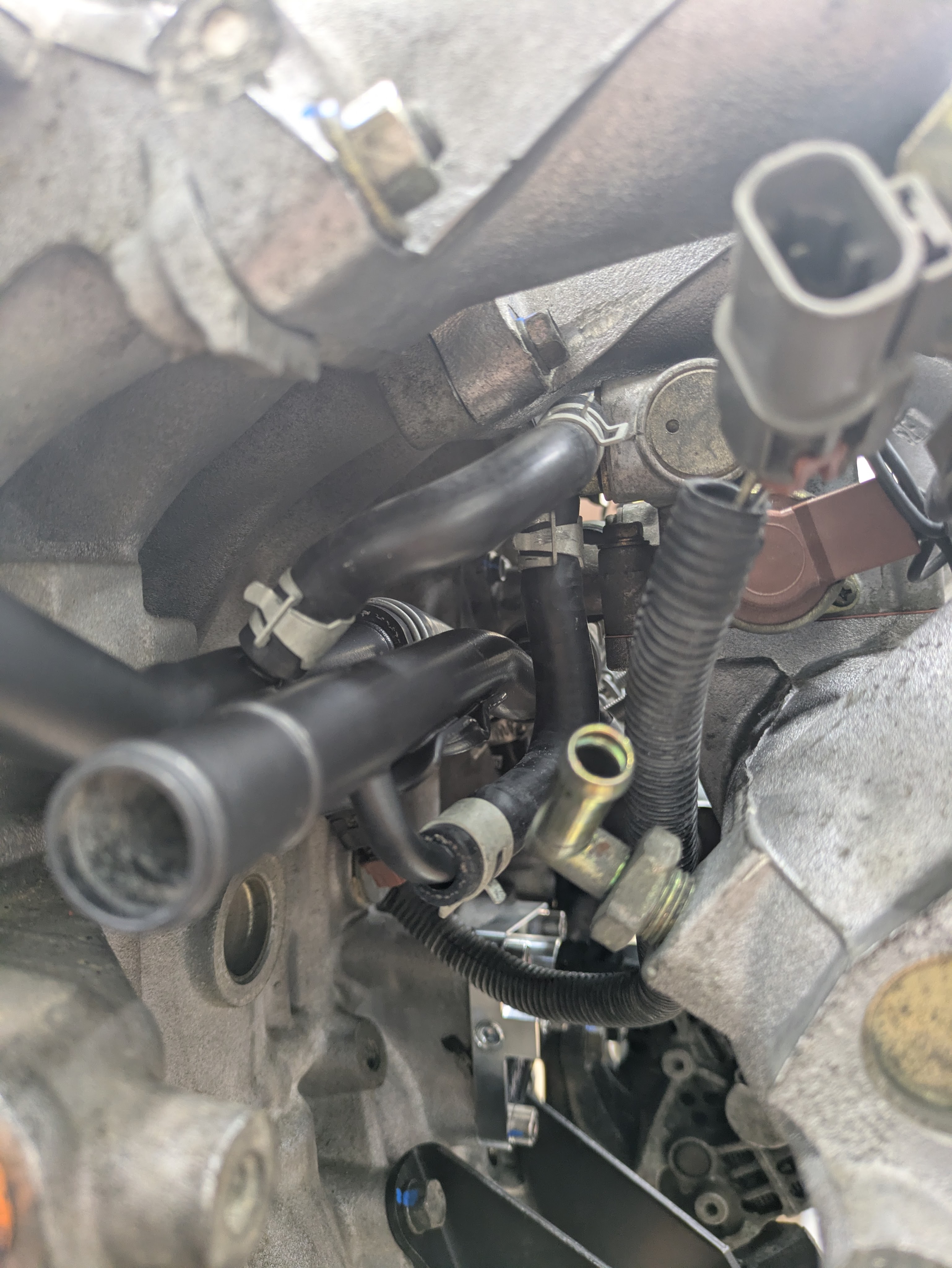
On to simplification: these are the OEM coolant pipes that run through the intake manifold from the thermostat to the firewall. They divert coolant to all sorts of locations, however the factory routing is suboptimal for a LHD application. The 90 degree corner that it takes around the back of the head is for the heater core, as well as the coolant feed for the turbo. Both of these are annoying to deal with.
The issue with the heater core routing is that since the heater core outlets are flipped versus what these pipes were designed for, the ideal hose routing would be for it to go straight back, parallel to the coolant pipes. While this is the configuration for one of them, the other takes a corner, then you need a 180 degree hose to turn back around and make another 90 degree corner to enter the heater core. While this is complicated and unnessary, it also puts a line behind the cylinder head which I deeply dislike.
The turbo feed is a separate problem but I’ll address that later. For now, just know that I also don’t want a turbo feed line running behind the head, navigating the hot turbo manifold, and into the turbo.
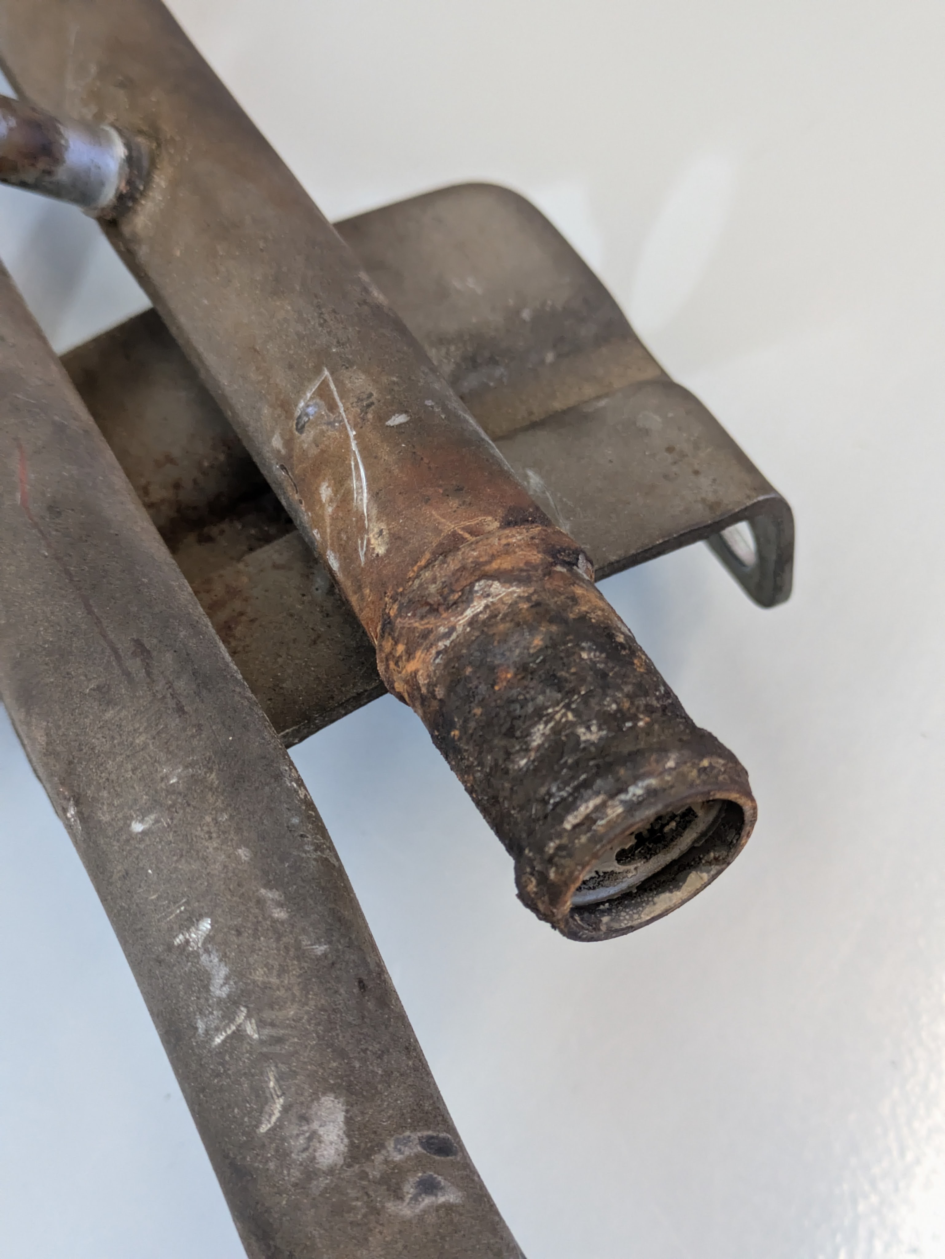
The pipes were obiously in poor shape as they had been buiried for 30 years, so a quick trip to work and the sand blaster took care of any aestetic aging.
While the barbs are still pitted, these are far better than they were before, and will have no trouble sealing.
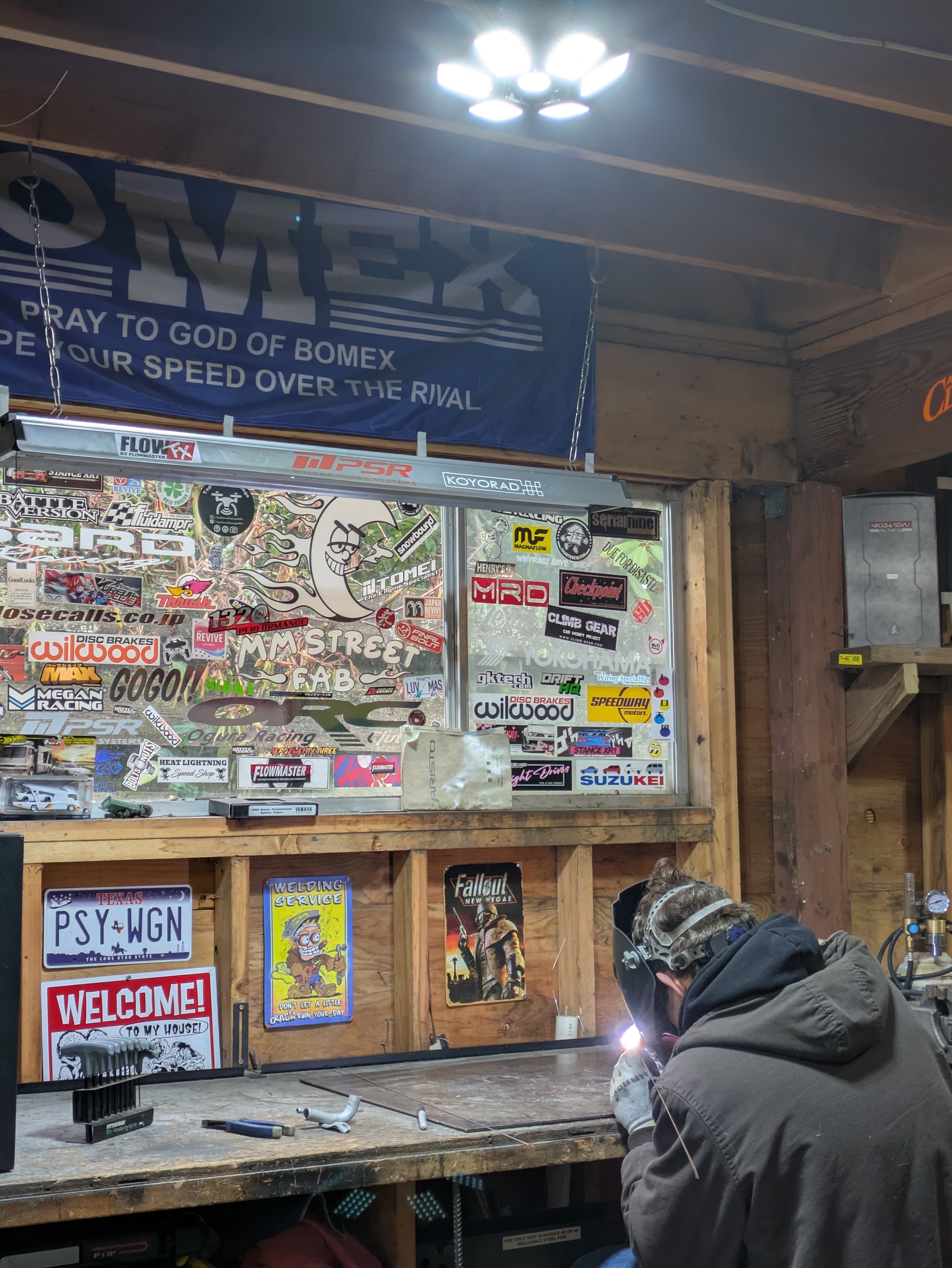
Once cleaned and prepped, I took a not-too-far trip to a fab friend’s house. I’ve known Ethan (@93_sc) for a bit, and it’s really nice to have a fabricator nearby for quick jobs. While automotive fab doesn’t pay his bills, his shop is more than capable of doing most work that comes his way, and my little weld project was peanuts for him. He will very likely be doing my intercooler and exhaust mods once the car is in one piece again.
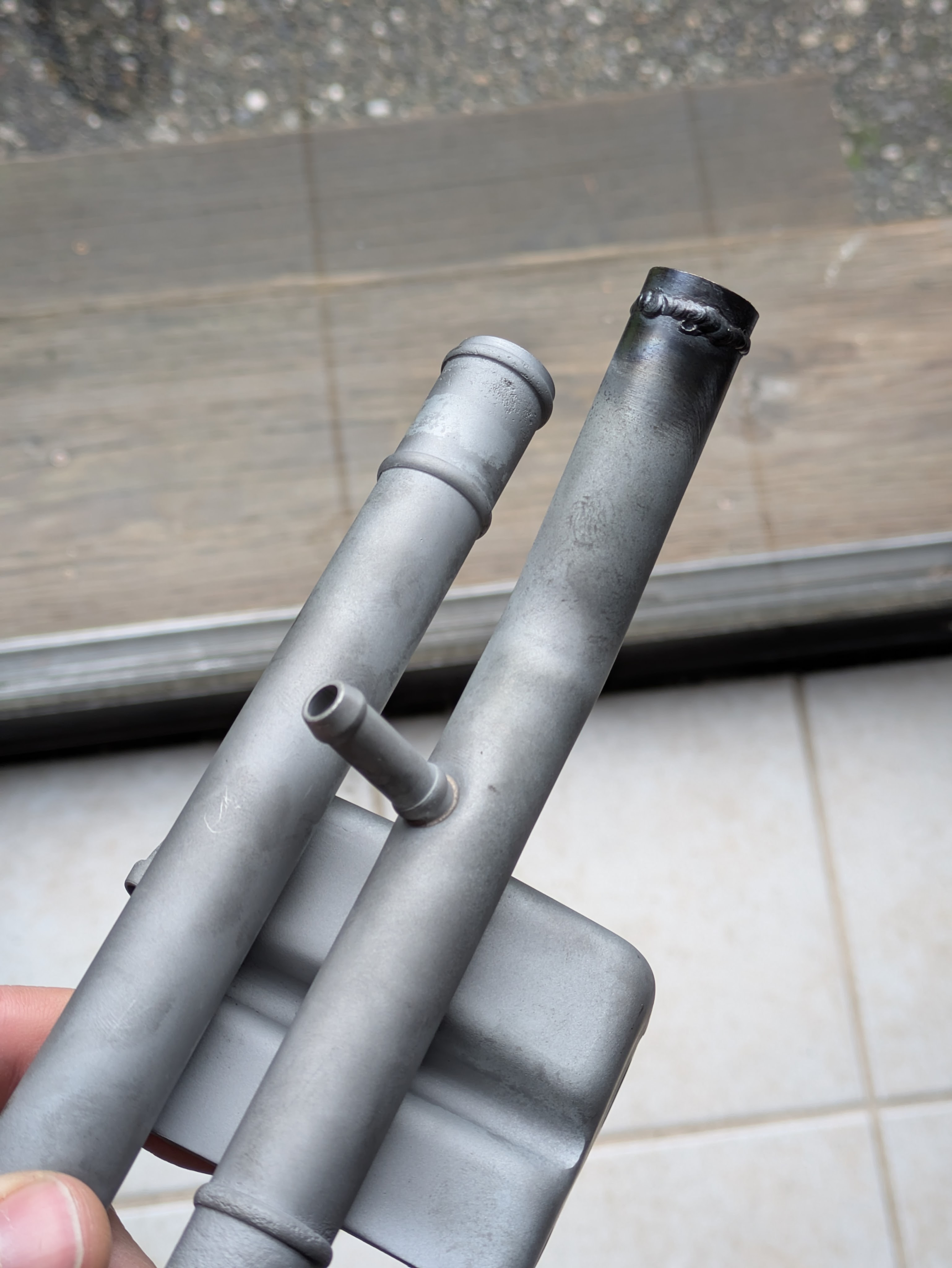
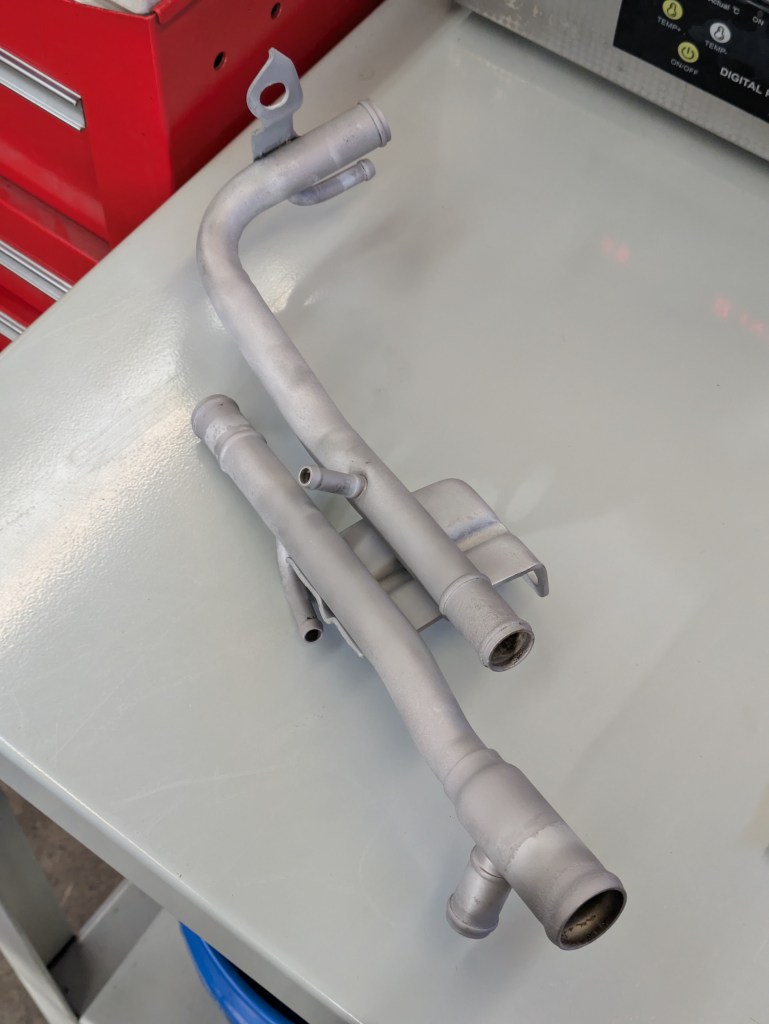
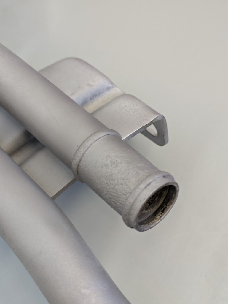
This was the result. We cut the pipes down to remove the extraneous length for the heater core and delete the turbo feed altogether, and Ethan tig welded a bead to retain the hose. This was just the slightest bit too small for his bead roller, so we opted to just weld it, and it turned out great. I laid down a few coats of Steel-It a few nights later, and they were ready for reassembly.
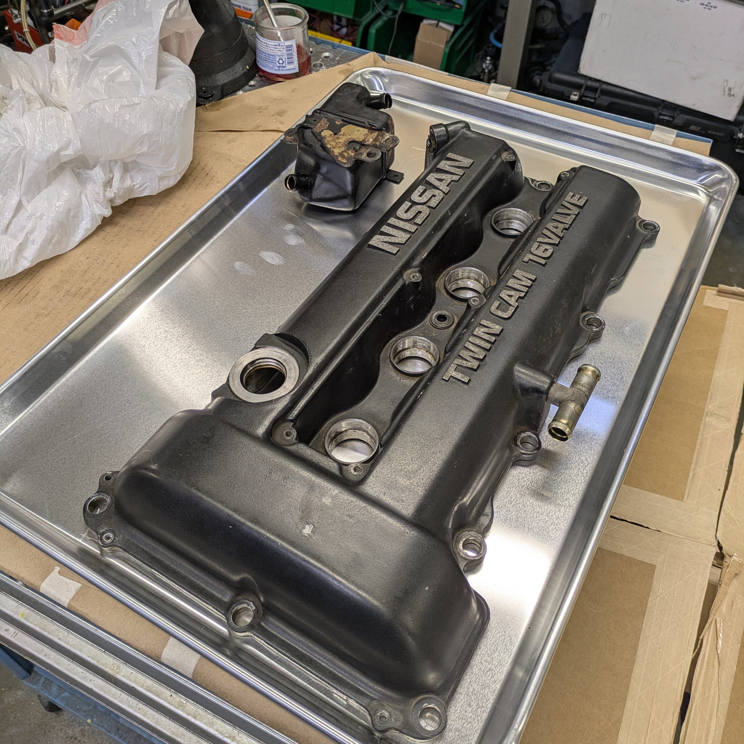
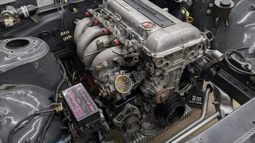
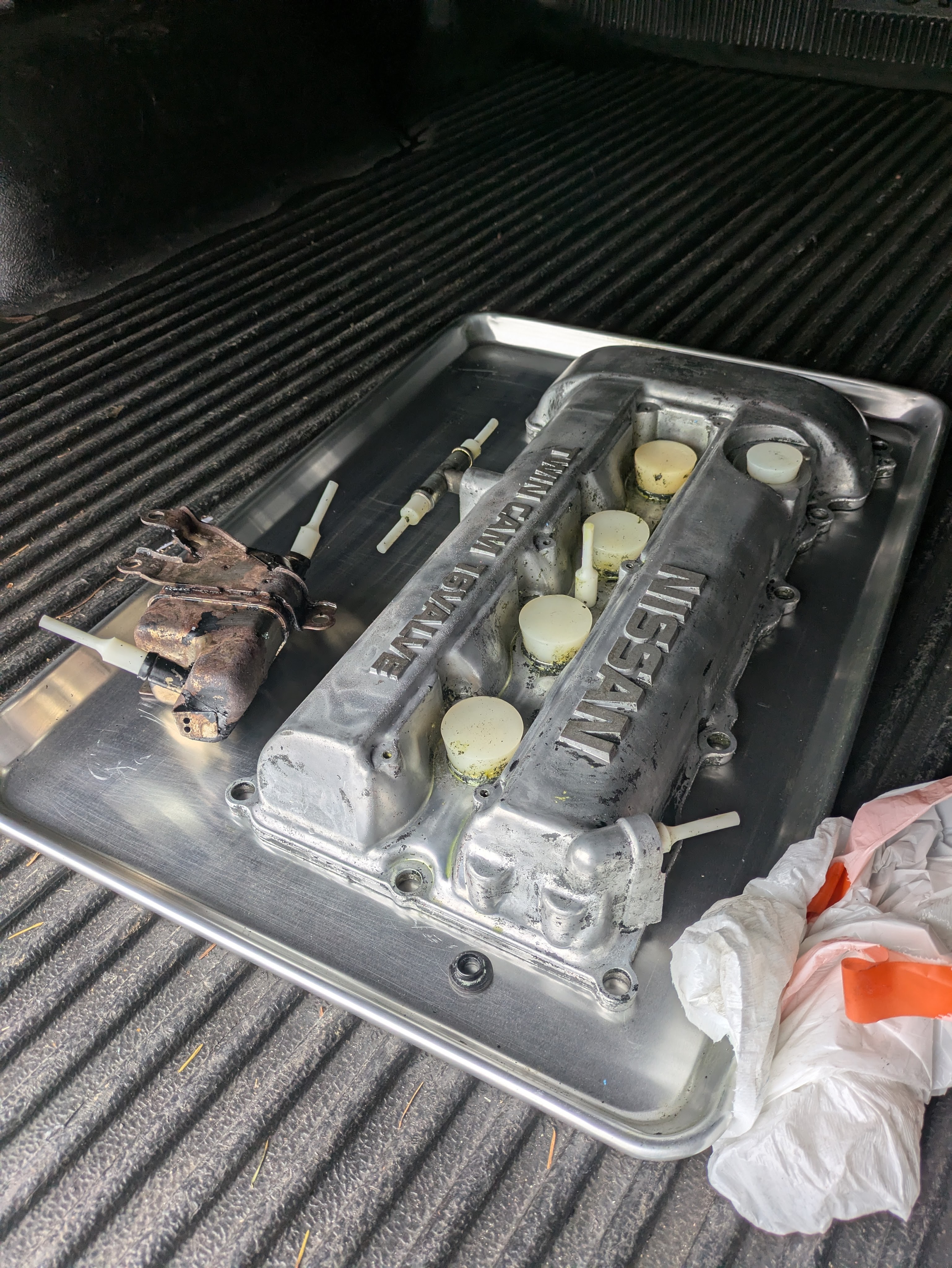
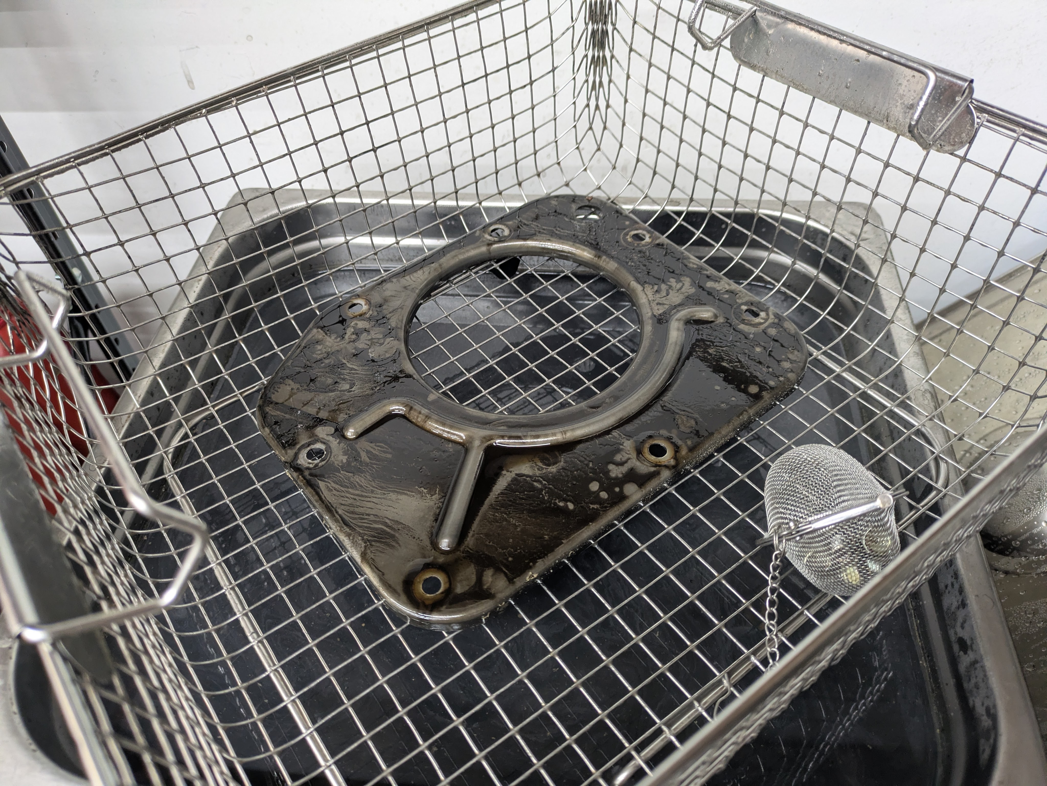
Moving on to aesthetics for a bit. SR20s are already very visually pleasant engine, but a properly painted valve cover is something they wear well. I have never painted a valve cover for myself before (done plenty for friends), so I was looking forward to actually enjoying the fruits of my labor for once. I also wanted to strip the crankcase air oil separator to refinish in black as it is prominently bolted to the side of the head.
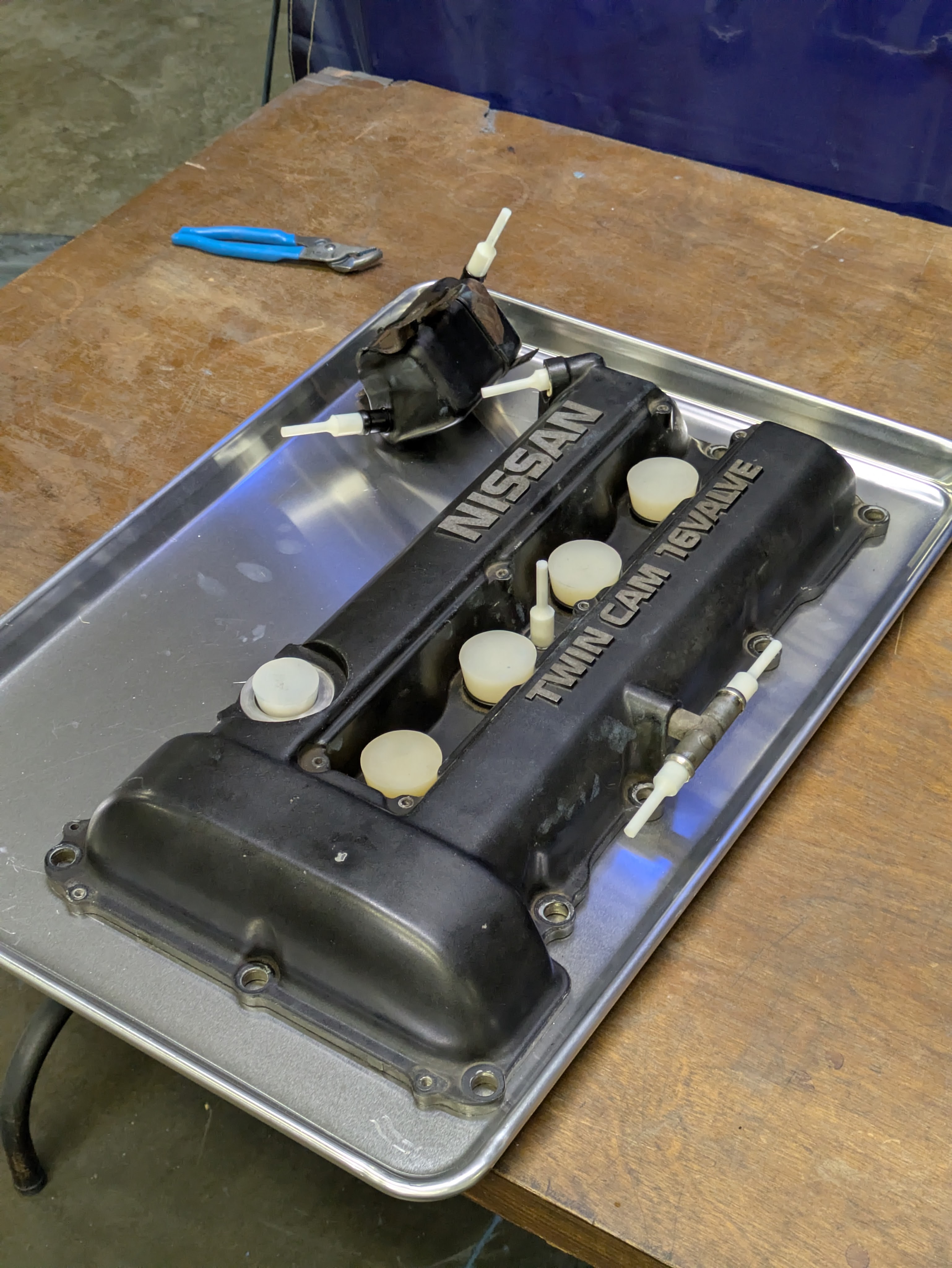
Fortunately, the coating cell at work had all of the right sized plugs sitting around to mask any critical bores. Since this came off a running engine, and I had no reason to remove the baffles, I wanted to avoid sandblasting at all costs. This was also my first time chemically stripping a valve cover (usually I just sand them), so it was all kind of new.
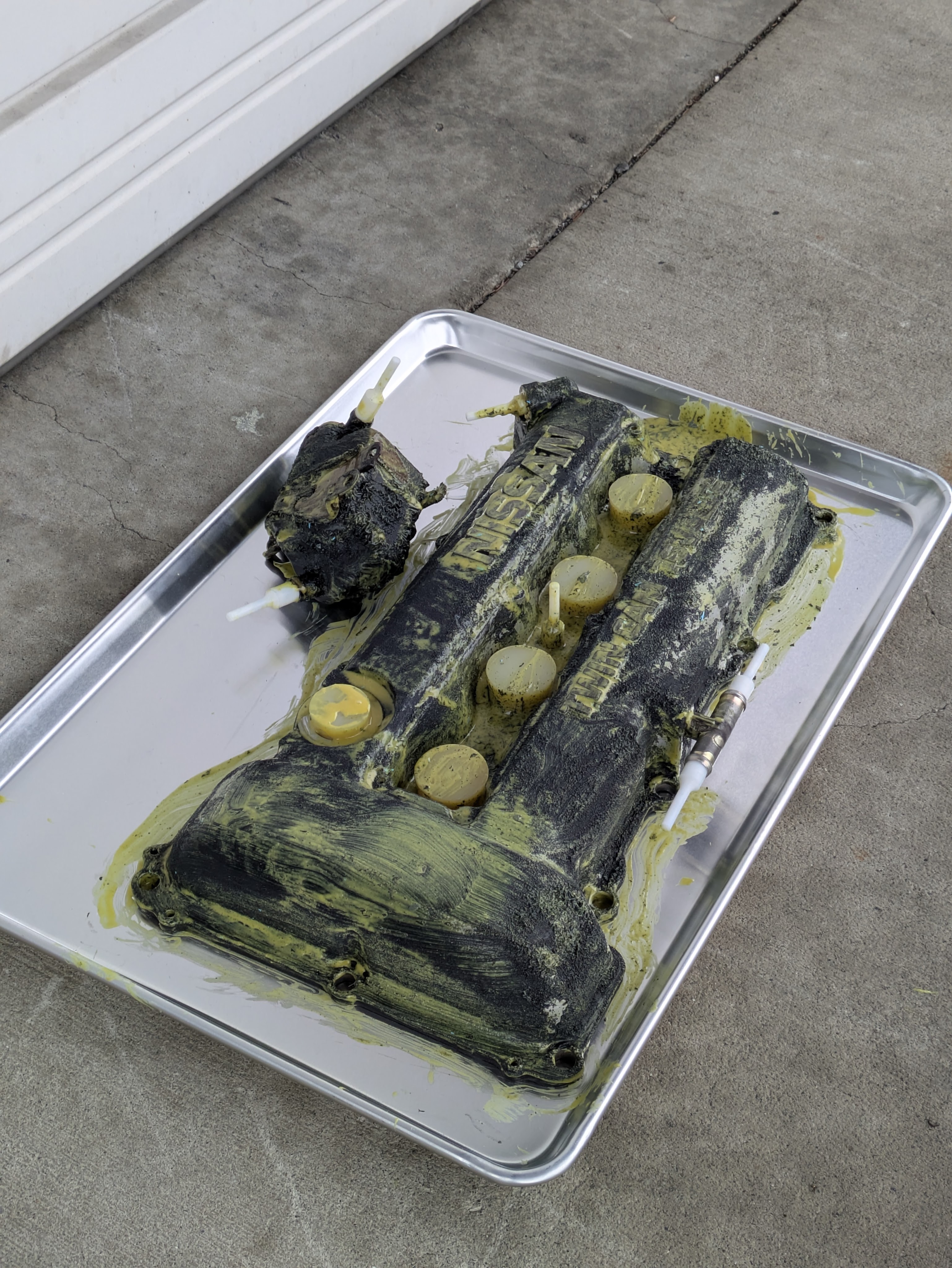
The paint stripper we had on hand was Cee-Bee Eldorado PR-3500, which is what we use to strip epoxy coatings off of helicopter grip bushings. This gooey yellow substance is even more destructive than the aircraft paint remover that you used to be able to buy at auto parts stores a decade ago. It would have filled the entire warehouse with fumes, so we brushed it on outside and let it do it’s thing.
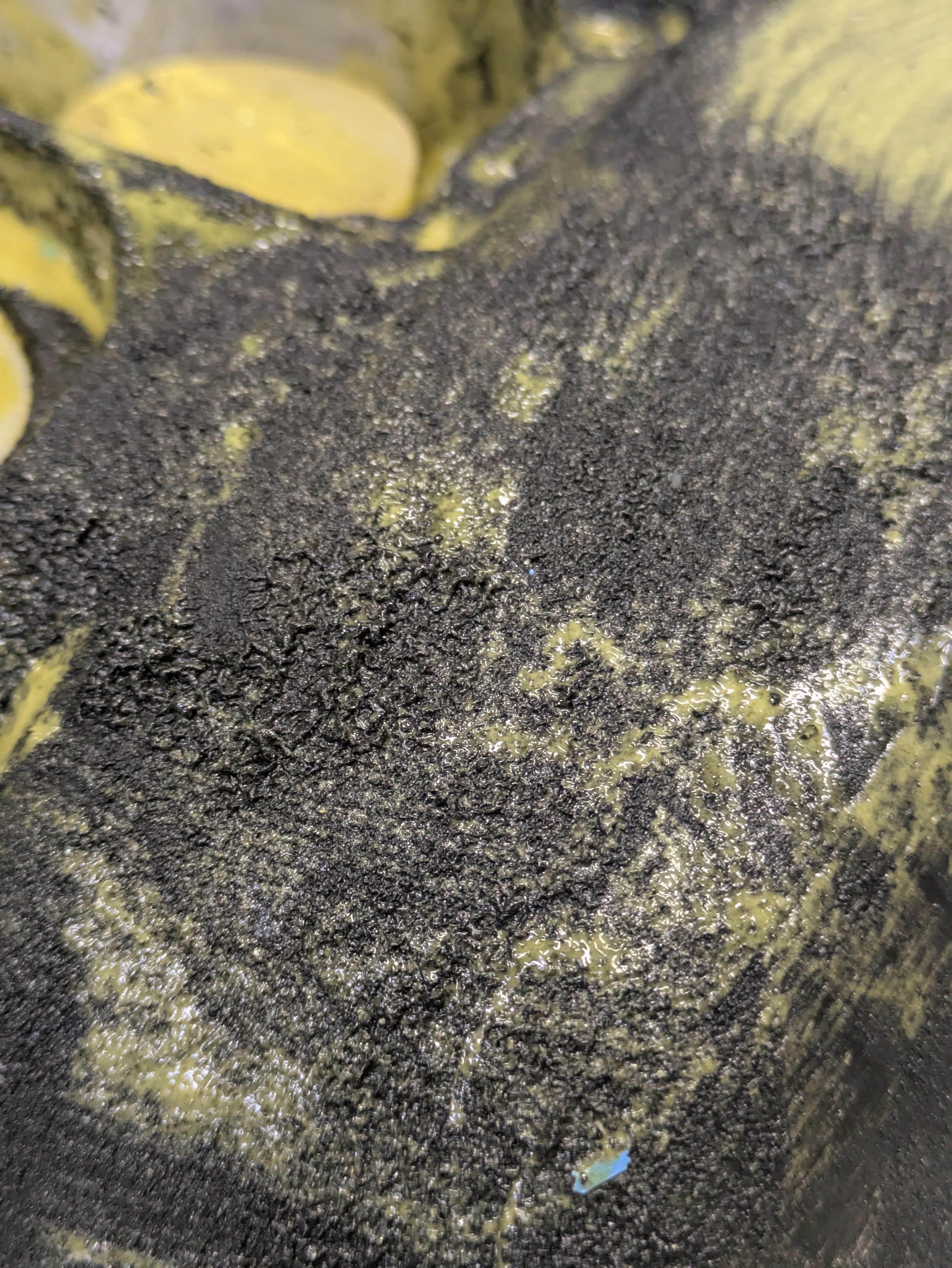
And do it’s thing it did. This was an excellent education for me on how effective these kinds of products are, and also how difficult it is to dispose of them once you are finished. I decided to leave the small stubborn spots to be dealt with during the paint prep process (which I am 100% delegating to my sister).
Back to mechanical stuff.
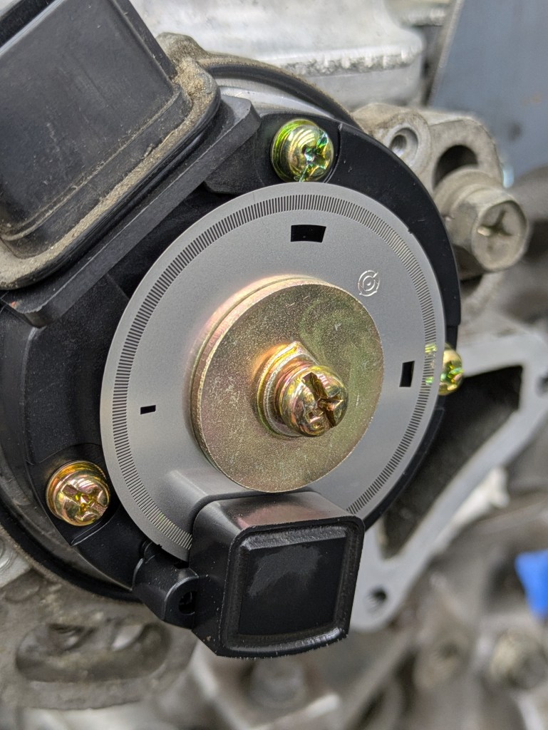
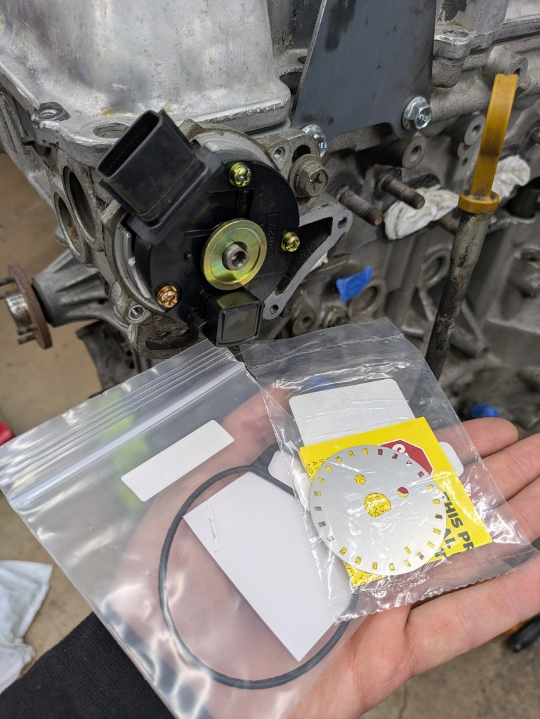
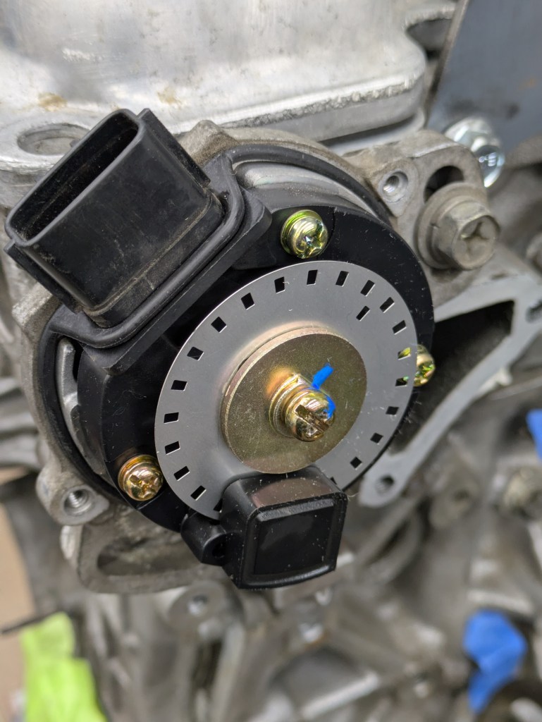
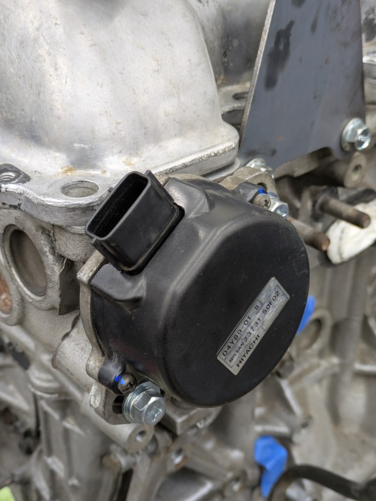
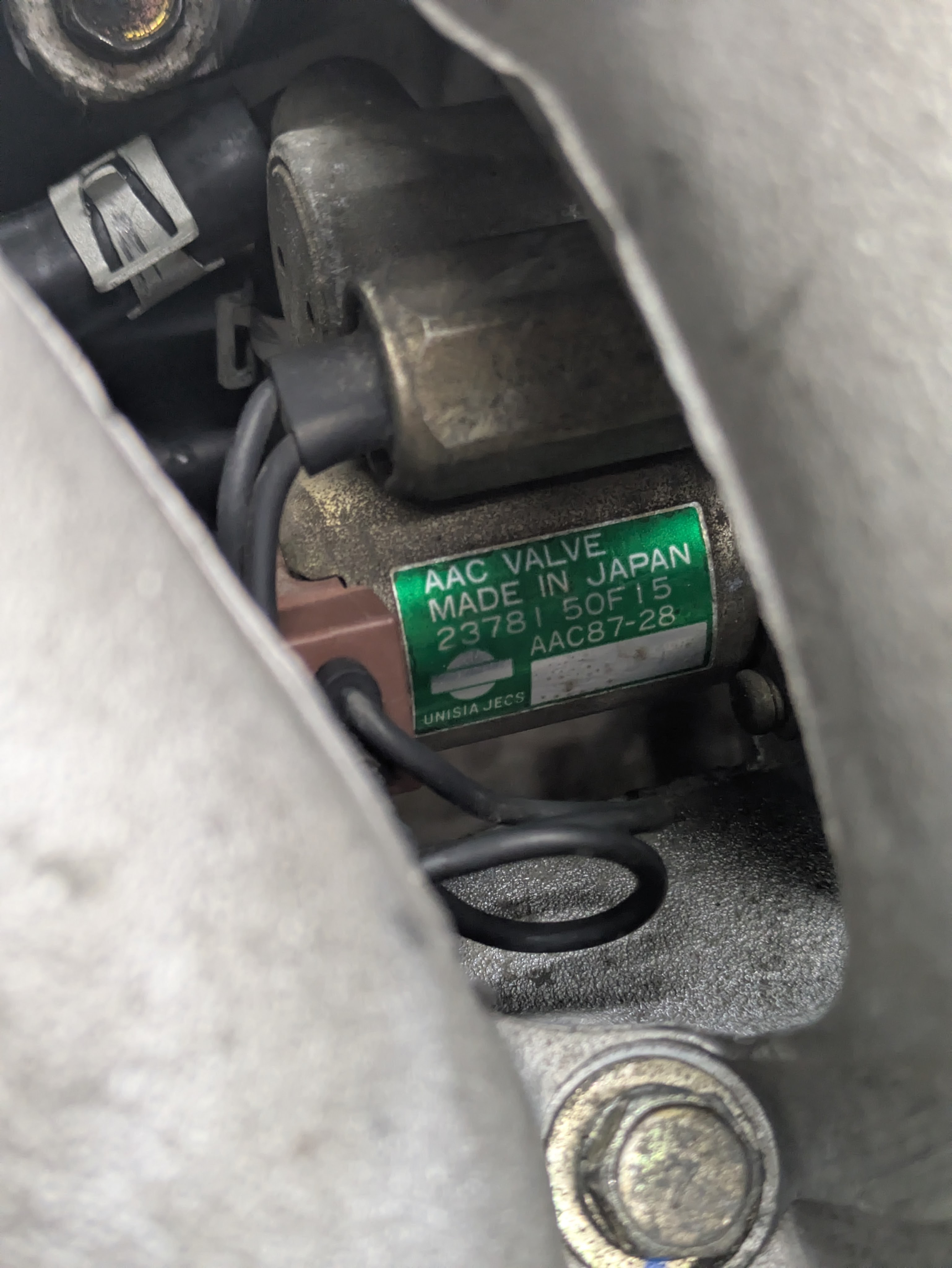
Mini project for a weeknight, and starting to creep towards reassembly: this is the factory Nissan Cam Angle Sensor. While plenty of capability for my goals, it’s fatal flaw is that Nissan gave the trigger wheel far too much resolution. It has a mark every 1 degree for 360 degrees, and while its normally ok, it is very easy for the computer to lose track of where it is if you hit rev limiter or are wildly varying in engine speed. Luckily AEM and a few others have made replacement trigger wheels that drop in with far more reasonable pickup resolution. Plenty for precise control, but significantly reduced risk of getting lost in all the action. It got a new gasket and brand new bolts (one was missing) to go along with it.
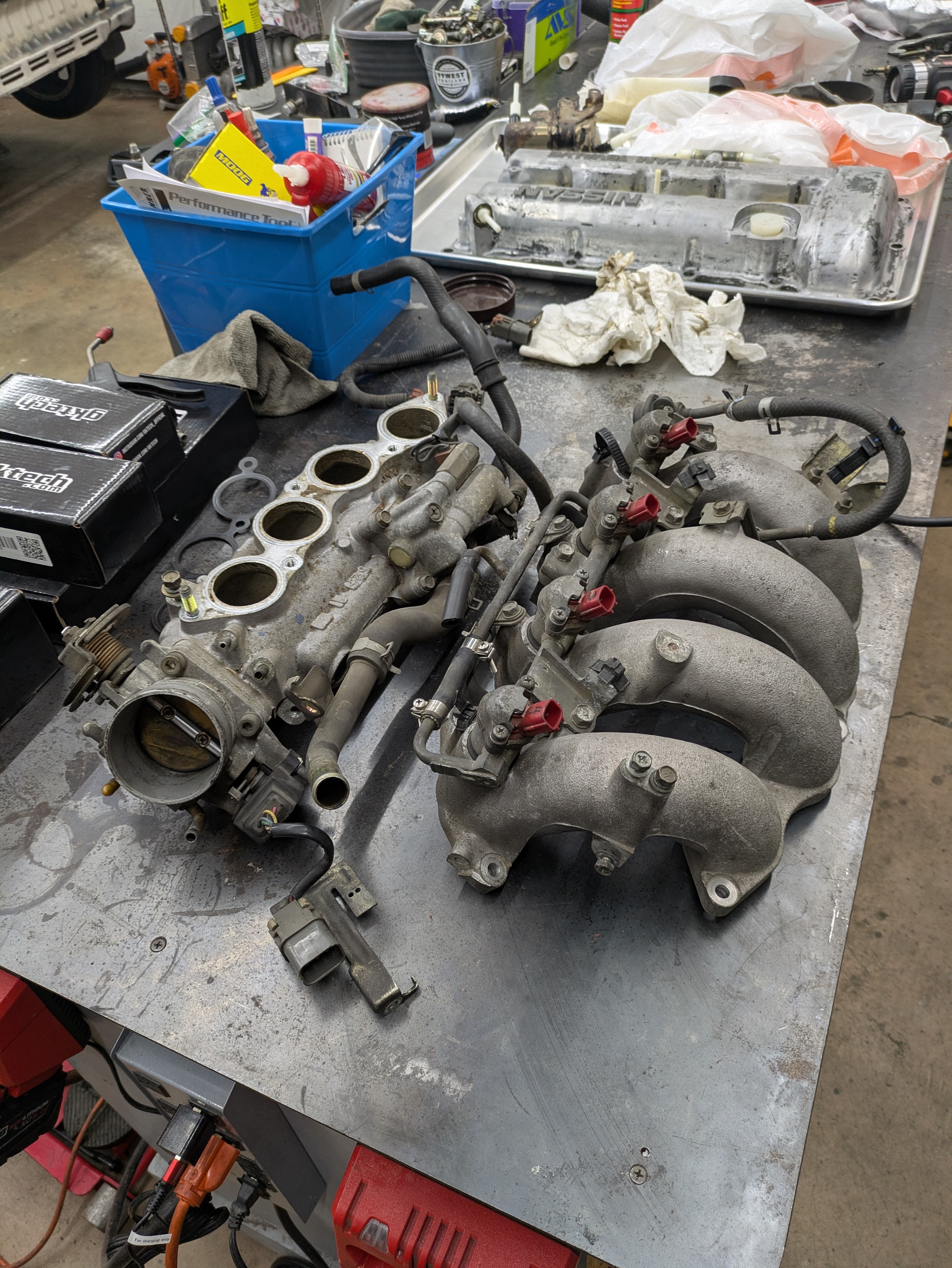
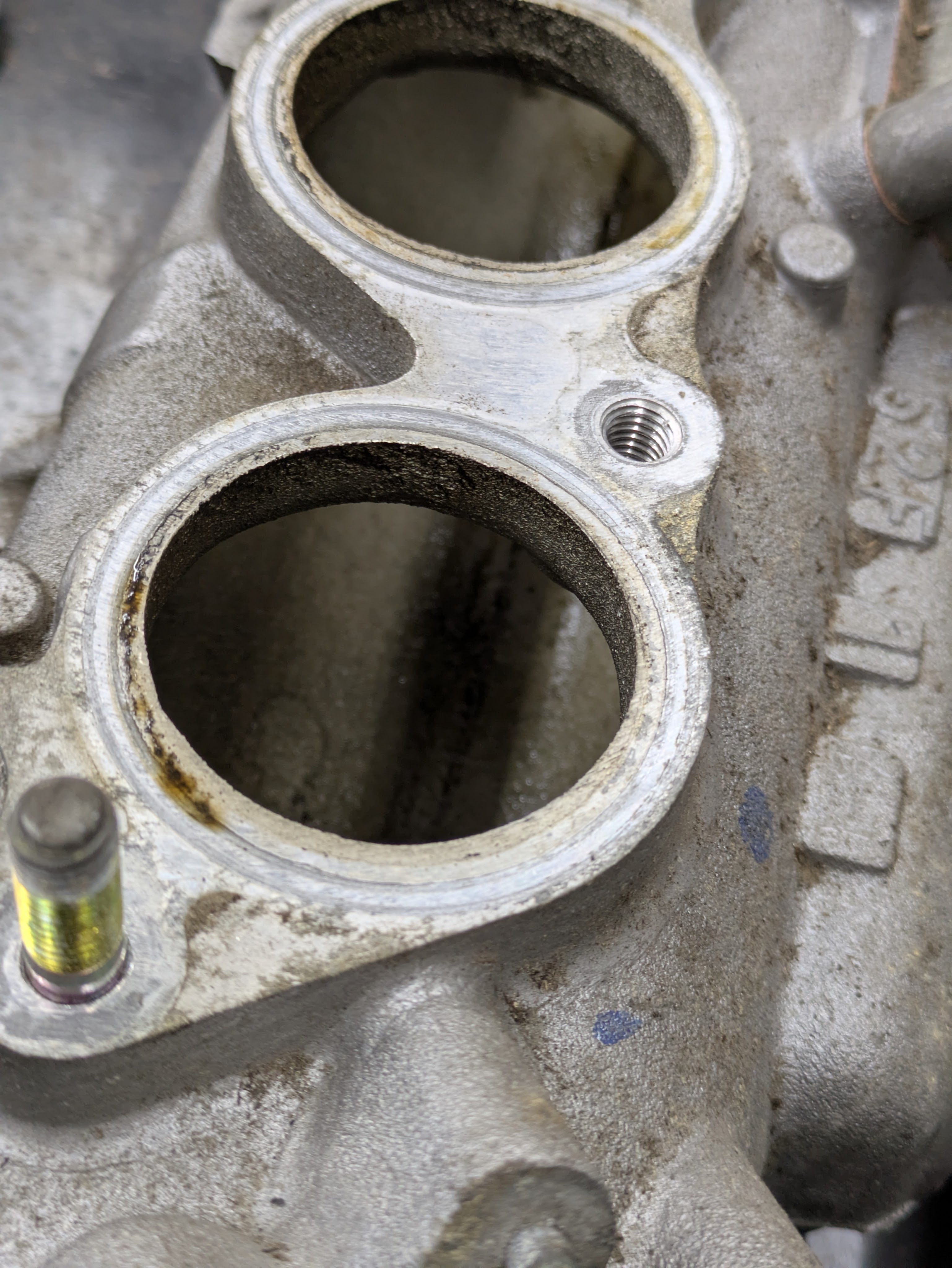
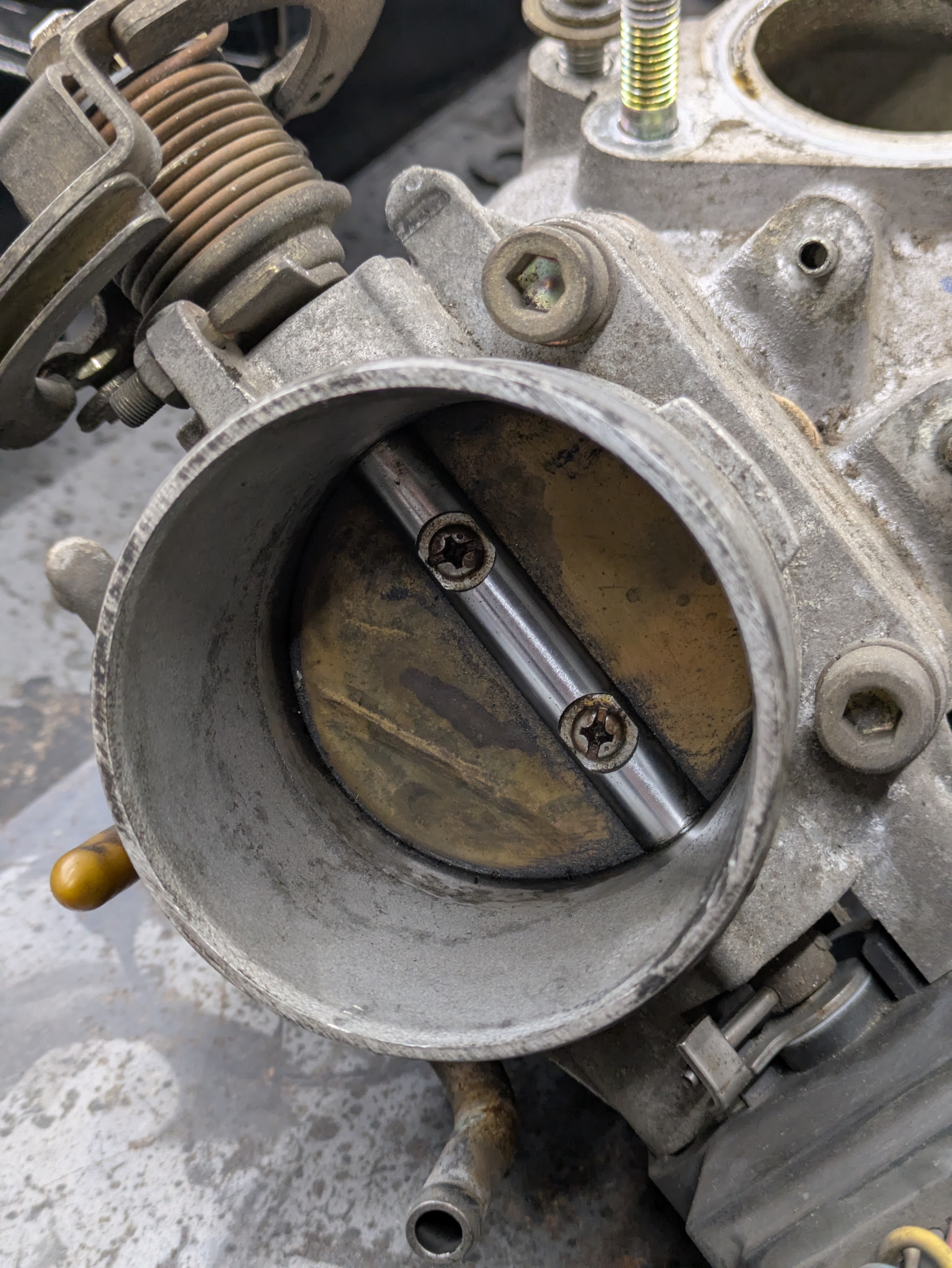
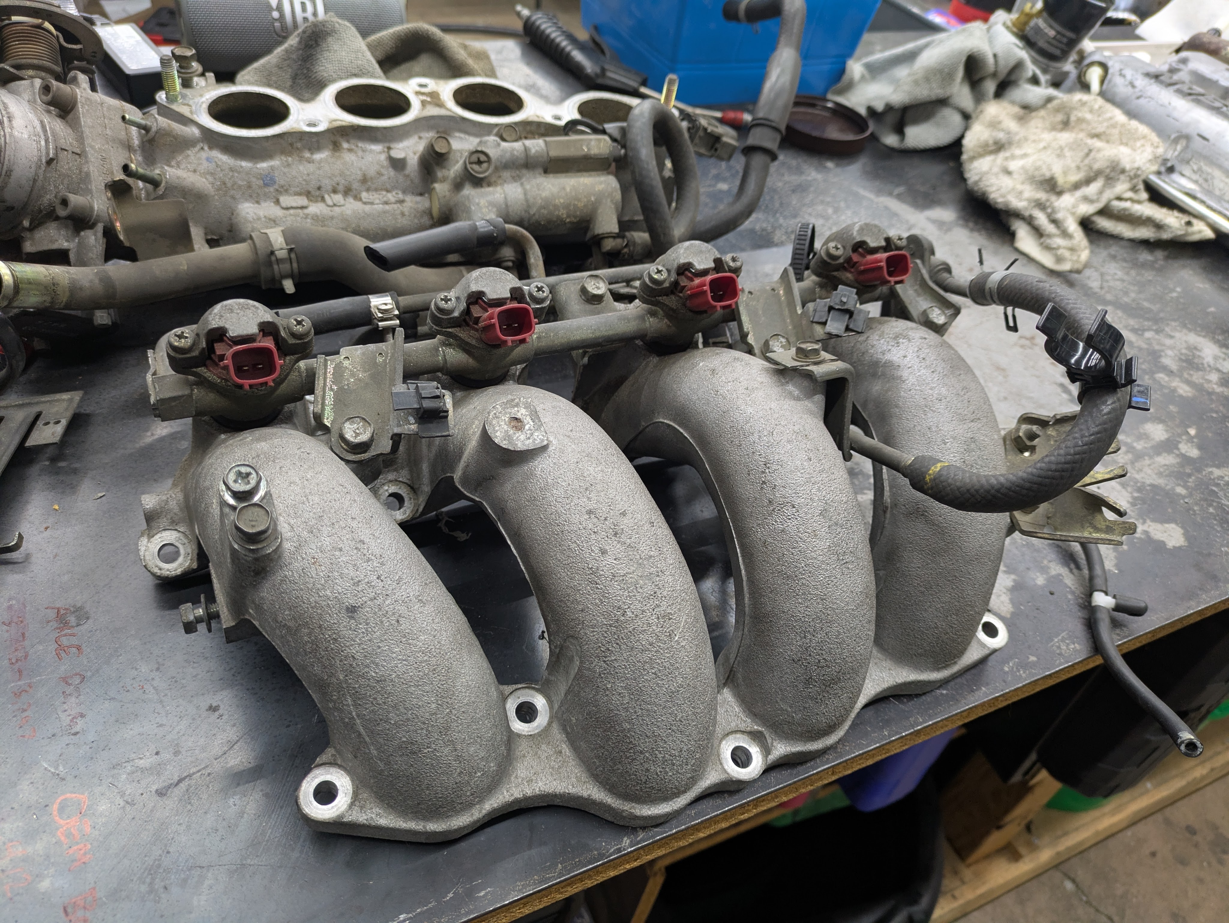
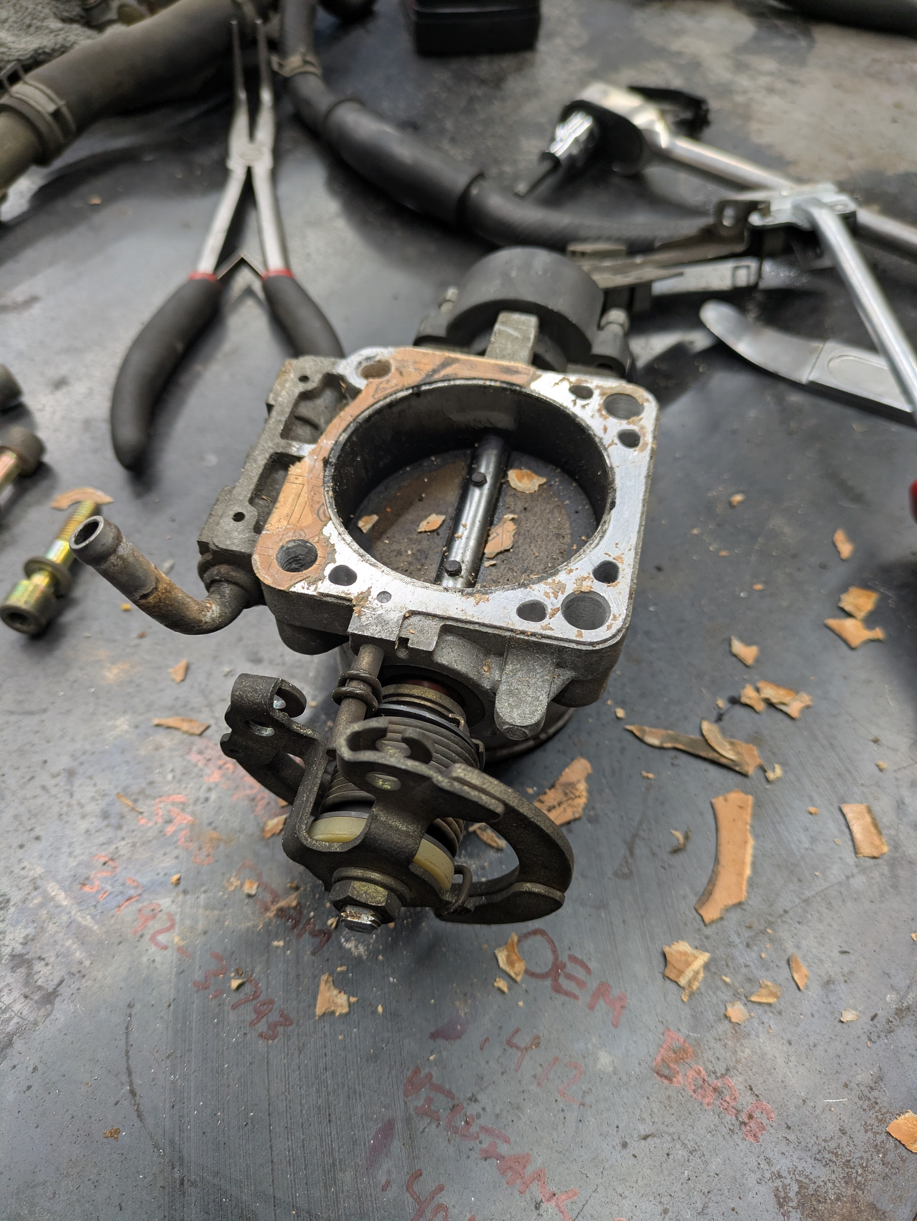
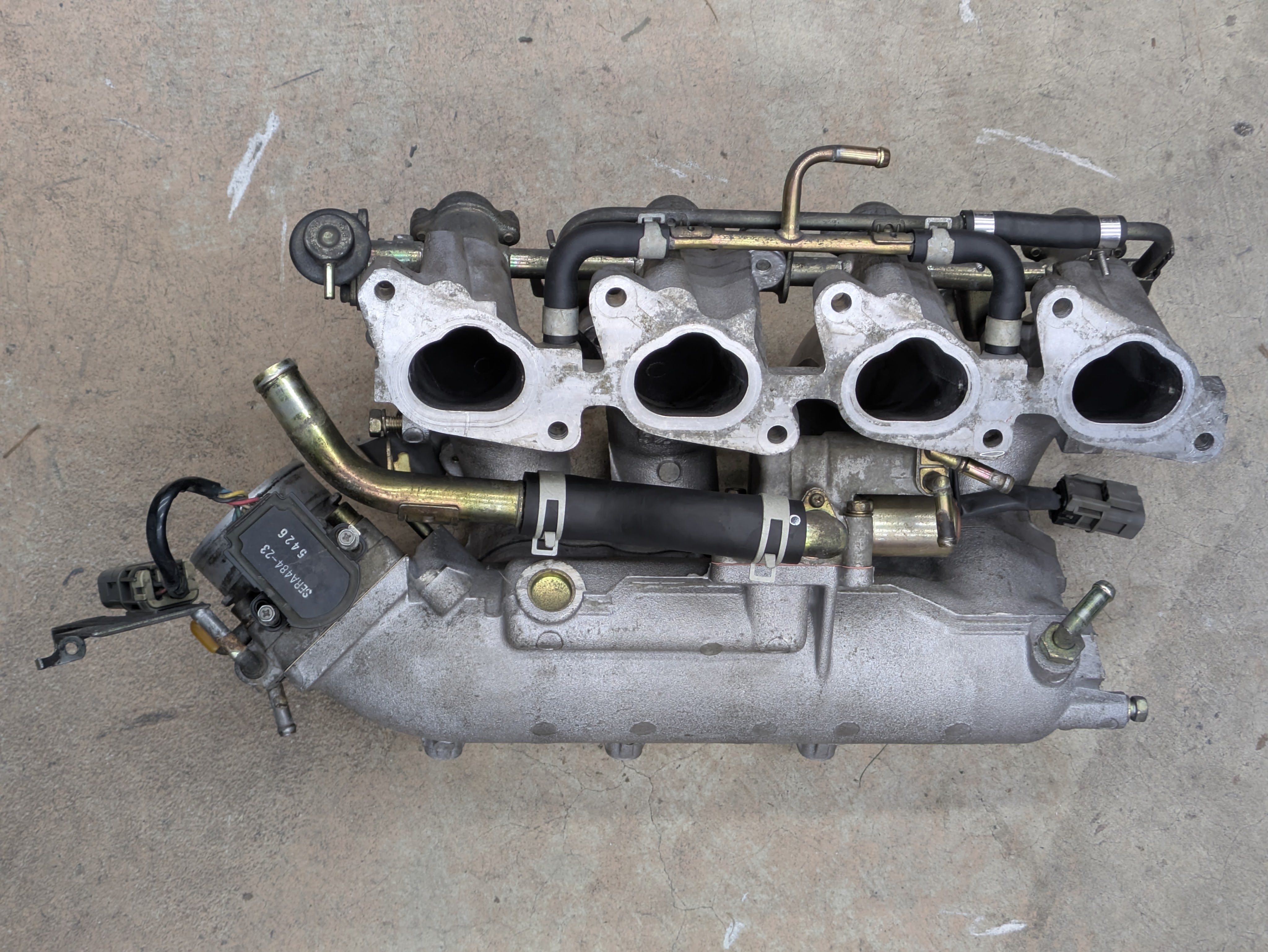
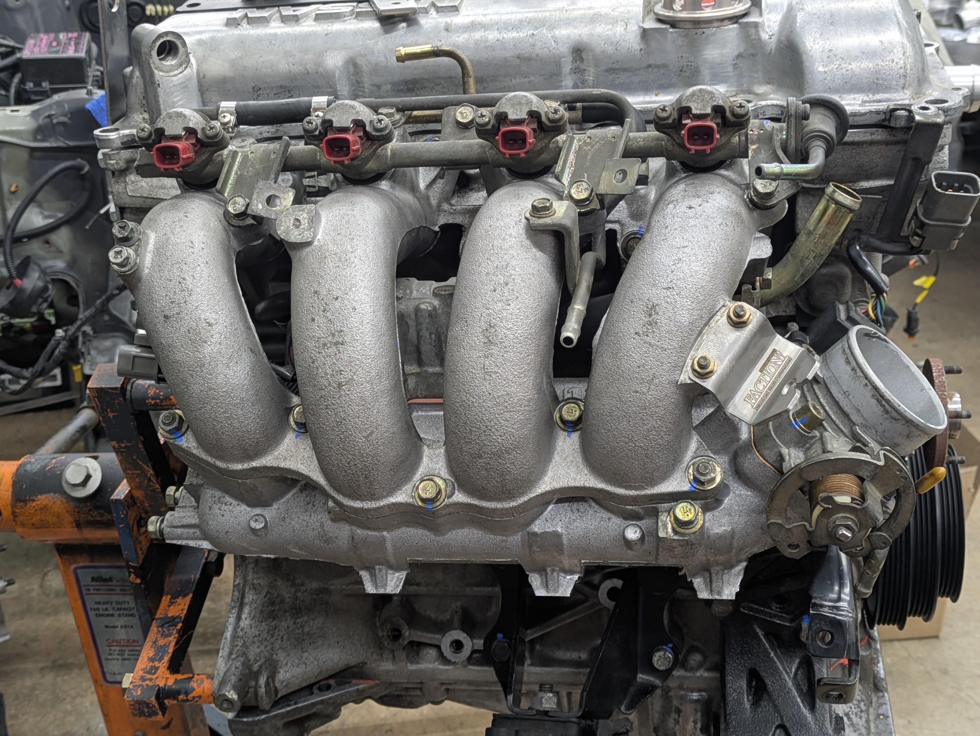
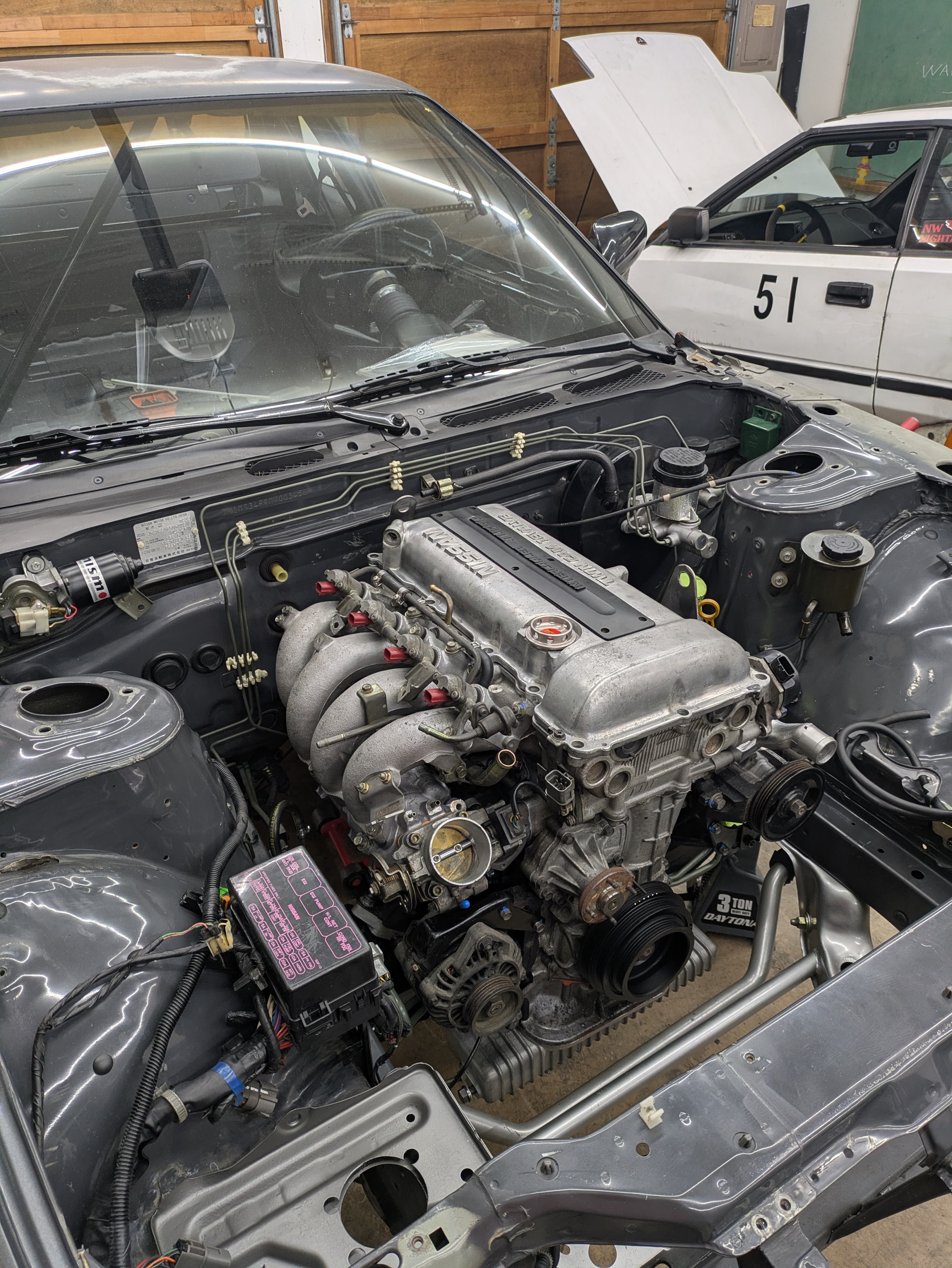
I got zealous a few nights later and wanted to tackle cleaning up and replumbing the intake manifold. Unfortunately, my ambition ran out shortly after these photos were taken, but these are a good showcase of the starting point. Not terrible, but also not what I want to bolt back on to a freshly cleaned engine. Those keen eyed of you will also note that this was originally an automatic SR20 by the throttle body connector.
Minus the welding, all of these tasks had been performed during the work week, either during or after work. What now begins is the big reassembly effort that occurred over a weekend. Keep in mind that this probably would have gone faster if it was literally freezing temperatures in my garage, but we work with the conditions that we have, and we have enough layers to stay alive.
I started by making our unpaid intern (Kai), scrape all of the RTV off the oil pan flanges, and composite gasket material off of the exhaust flange. Kid has to learn somehow, and I was busy dicking around with reassembly.
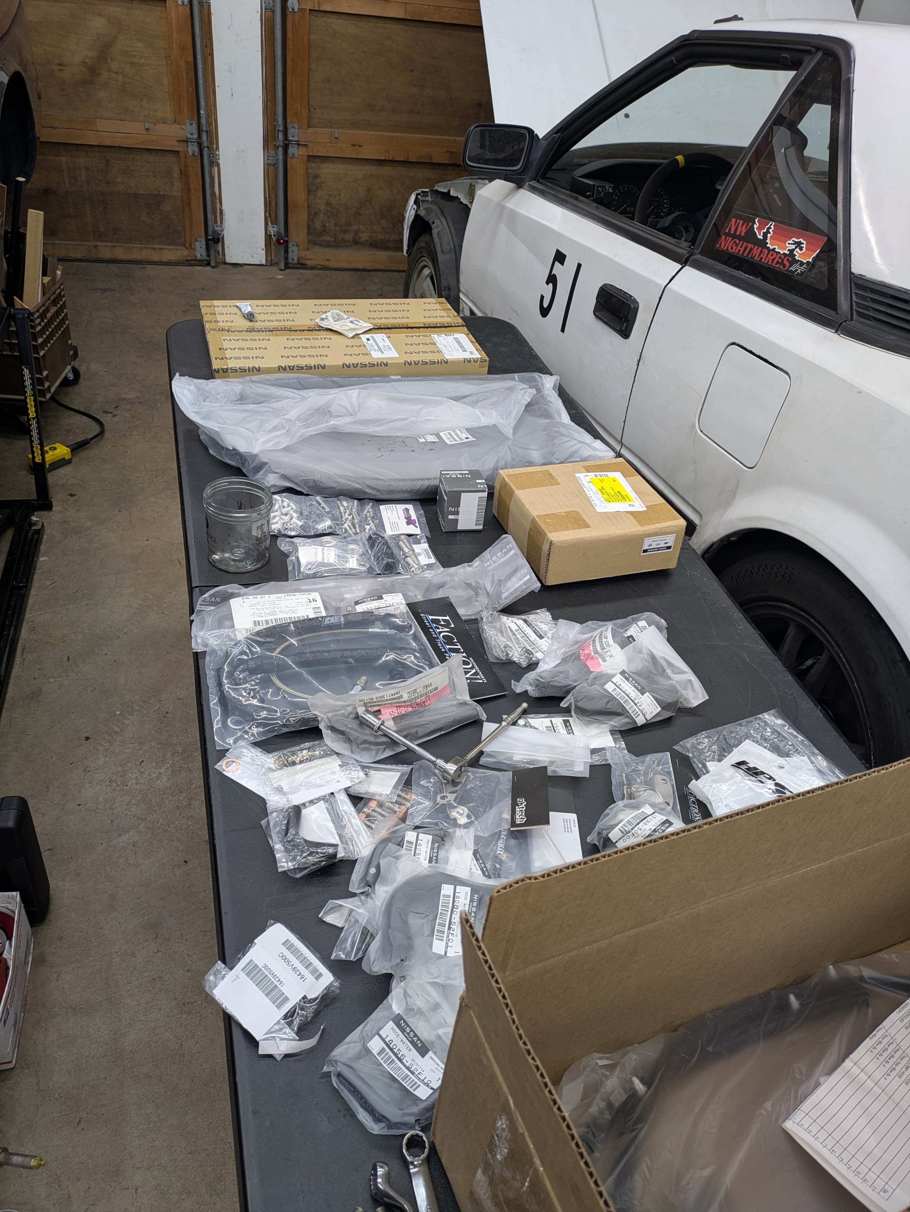
In fact, here’s a table full of tasks. While not as expansive as when I restored my VFR800 in terms of number of OEM bags on a table, its nice to be able to spread them out and stack them based on location or system.
The goal of this weekend was to get the longblock assembled with all of it’s accessories, and get the oil pan (both upper and lower) resealed and reinstalled.
I did a pretty poor job of documenting this day, including the install of the ultrasonic cleaned upper pan and brand new Greddy lower pan that I had failed at installing a few months prior due to swaybar clearance. This was mostly because my hands were covered in oily gasket sludge from cleaning up mating surfaces, but day two moves a lot quicker, and with way more content.
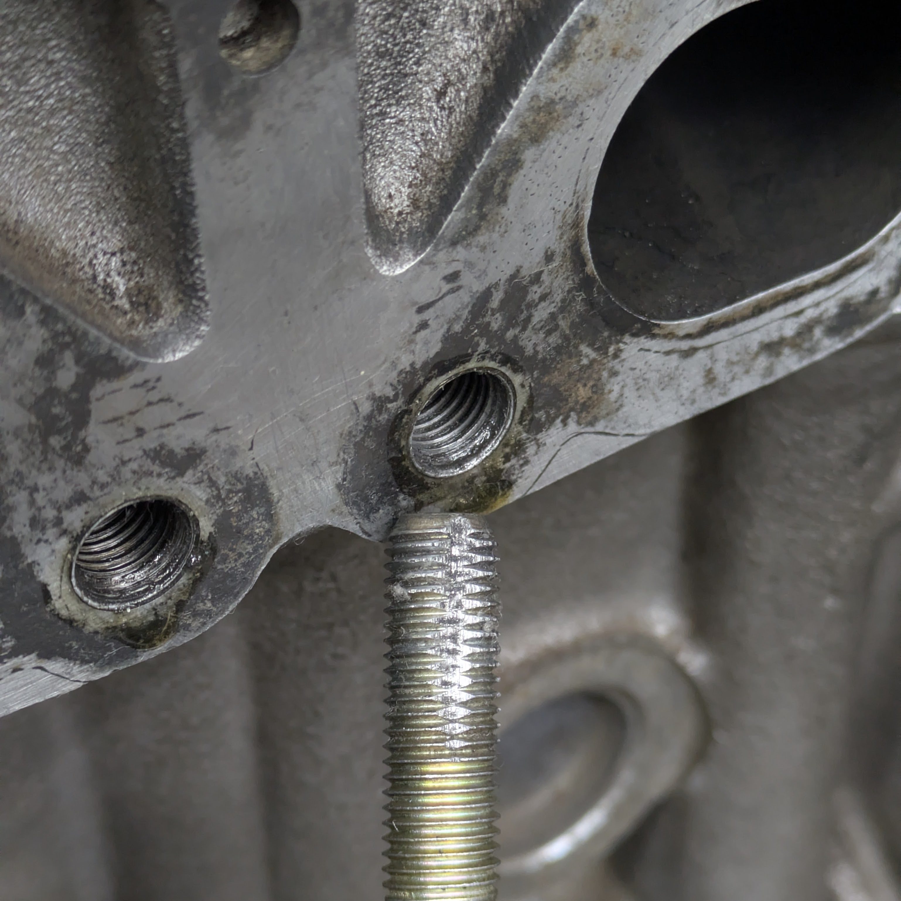
I started off by cleaning up the threads in the exhaust stud locations with a self-made thread chaser/cleaner (a bolt with some slits in it for the debris to go). Highly recommend using these if you have good threads that don’t need to be re-tapped for geometry issues as this maintains the thread tolerance rather than expanding it. While there are off the shelf products for this purpose, this works great and take 30 seconds with a cutoff wheel to make.
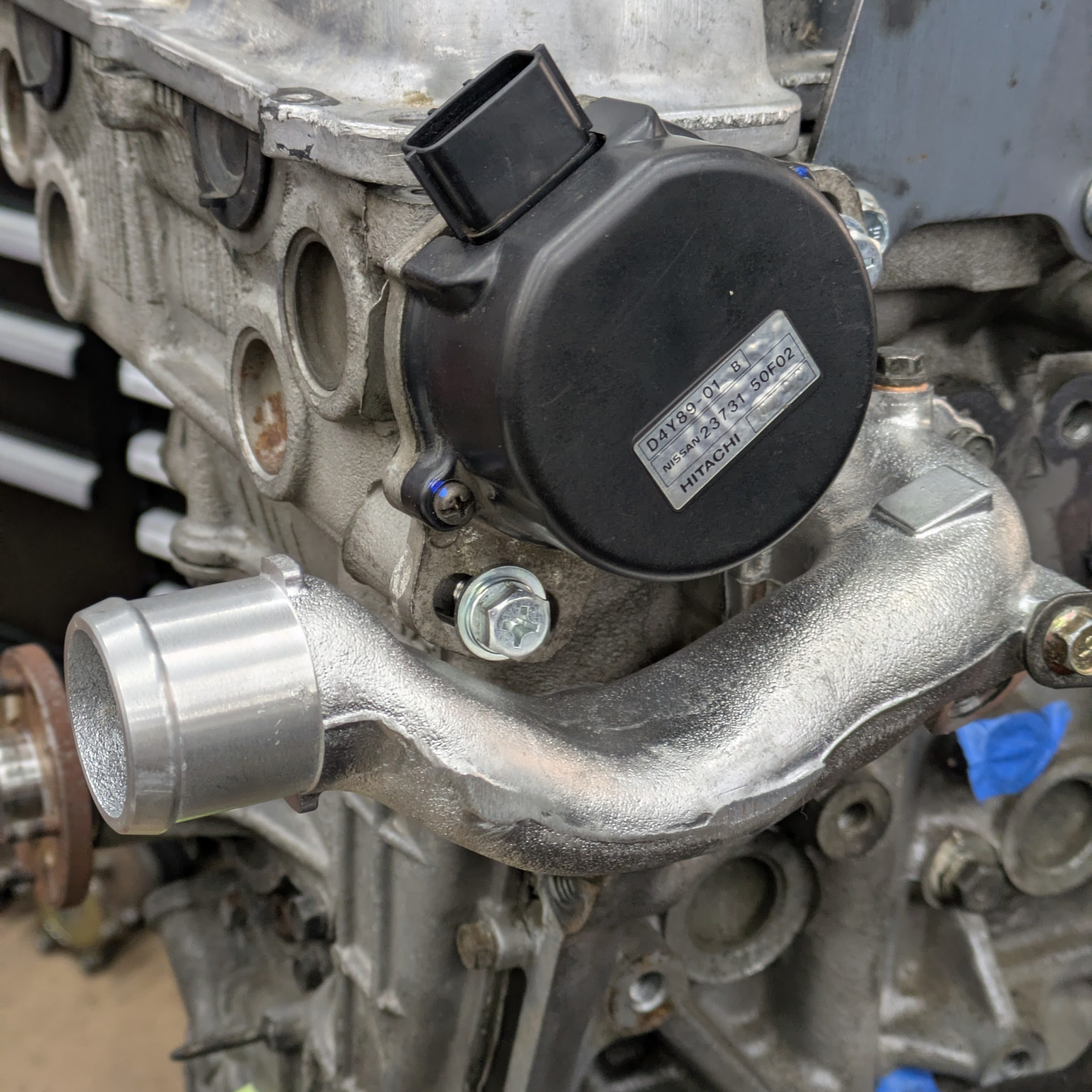
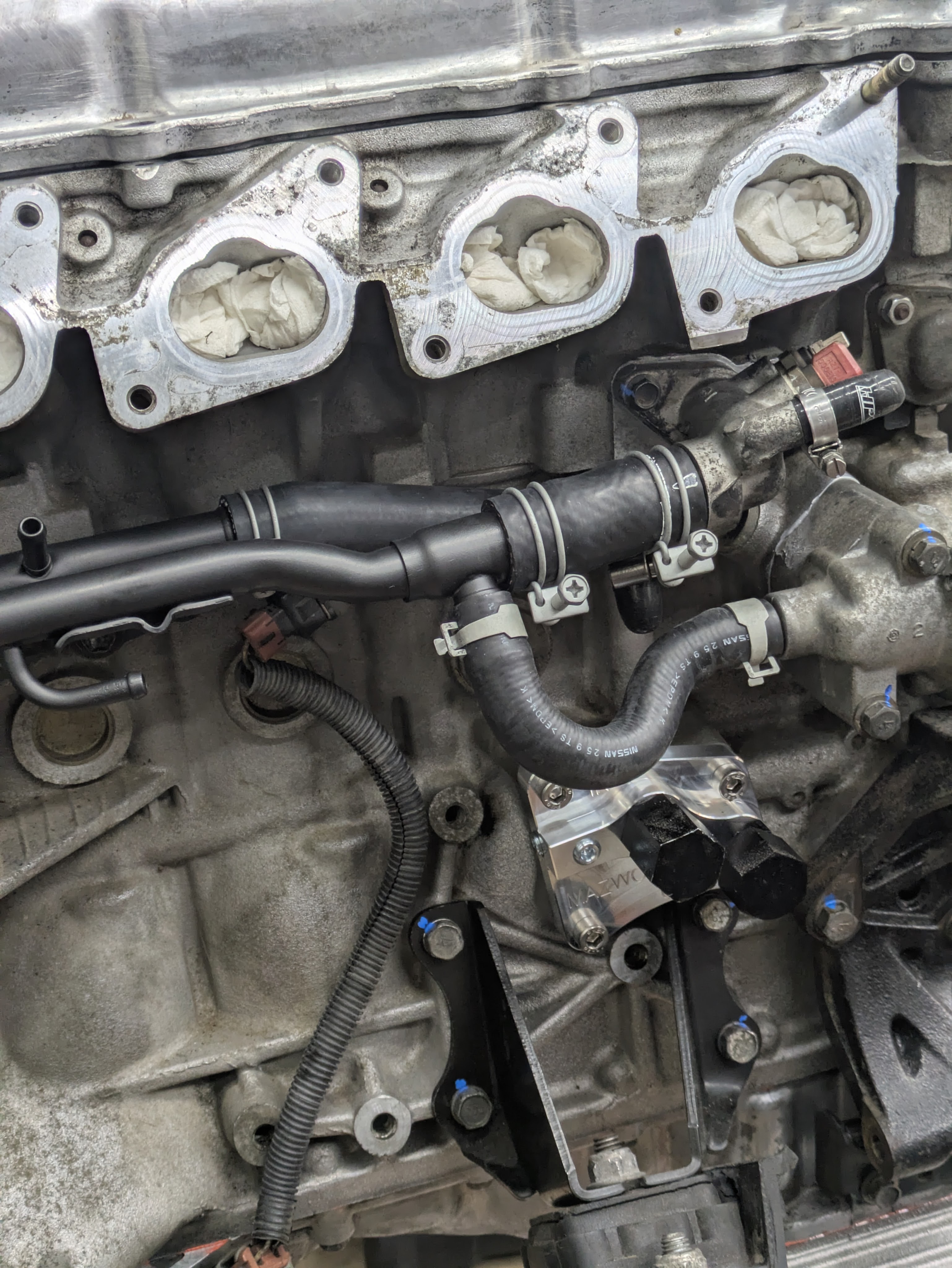
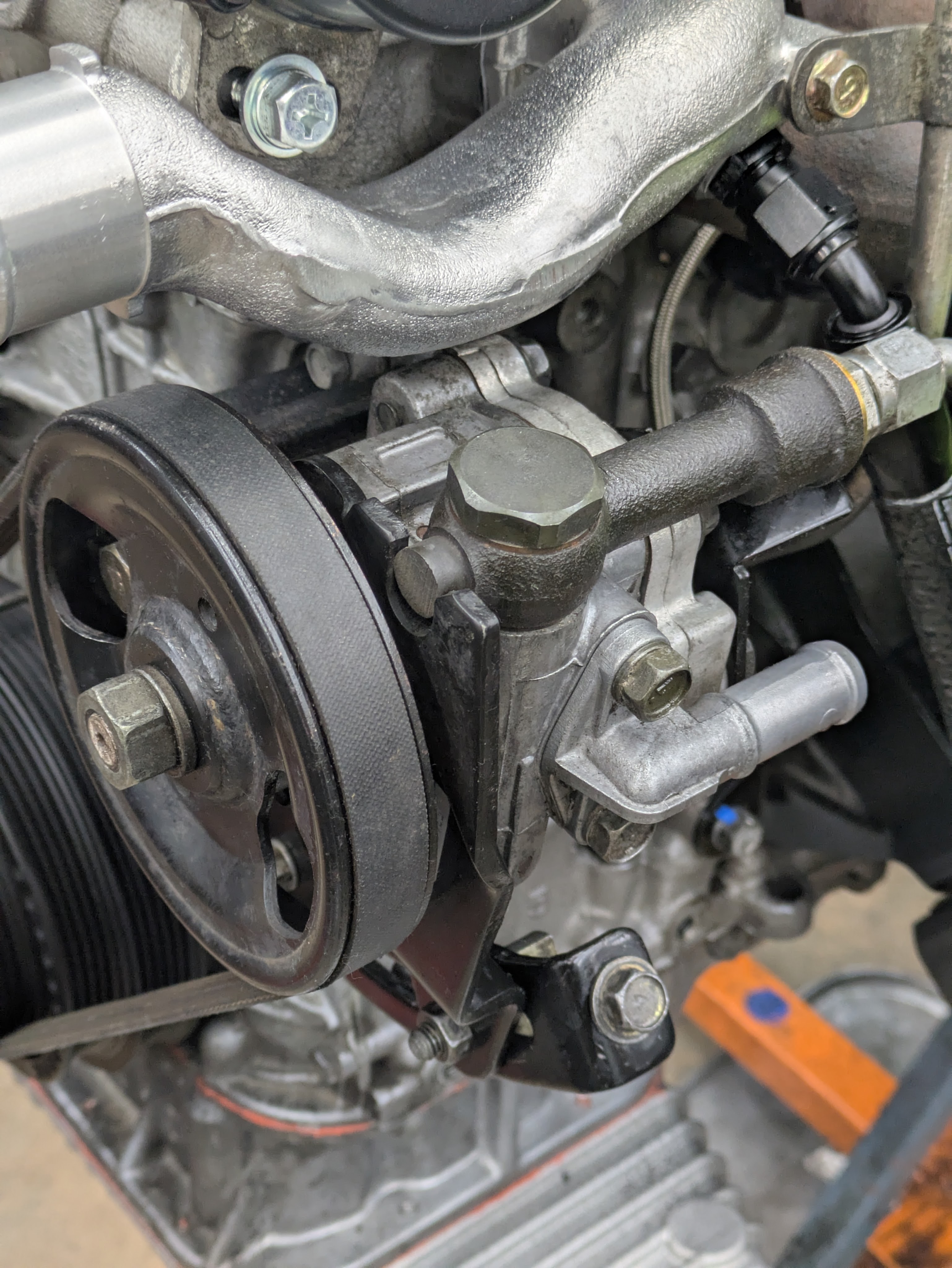
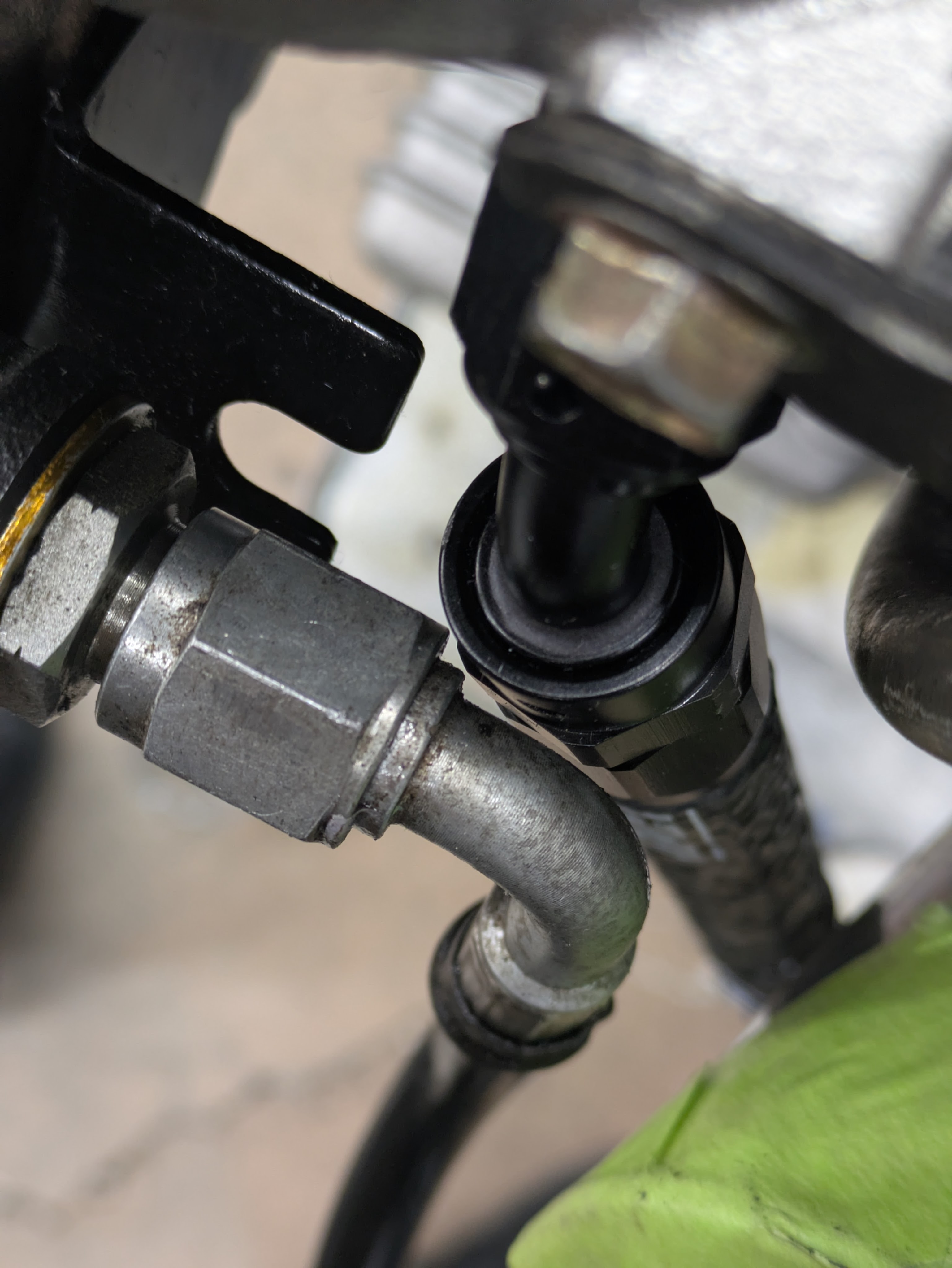
Before proceeding with the turbo, I got the S14/S15 upper water neck installed. While geometrically the same as the S13 one, the S14/S15 added a fitting provision to the water neck, allowing you to delete the coolant feed from behind the head and run it in a much more sensible fashion. This was a pretty penny brand new from Nissan, but it was worth it. My old motor had one, and the turbo lines were so much more pleasant to deal with.
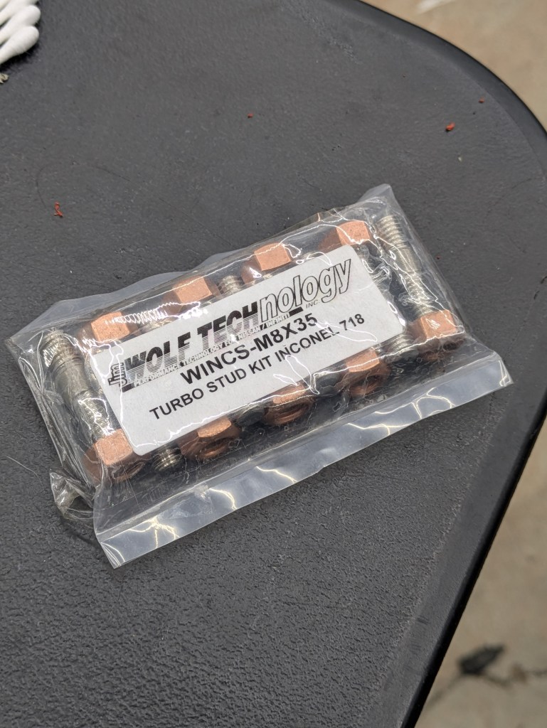
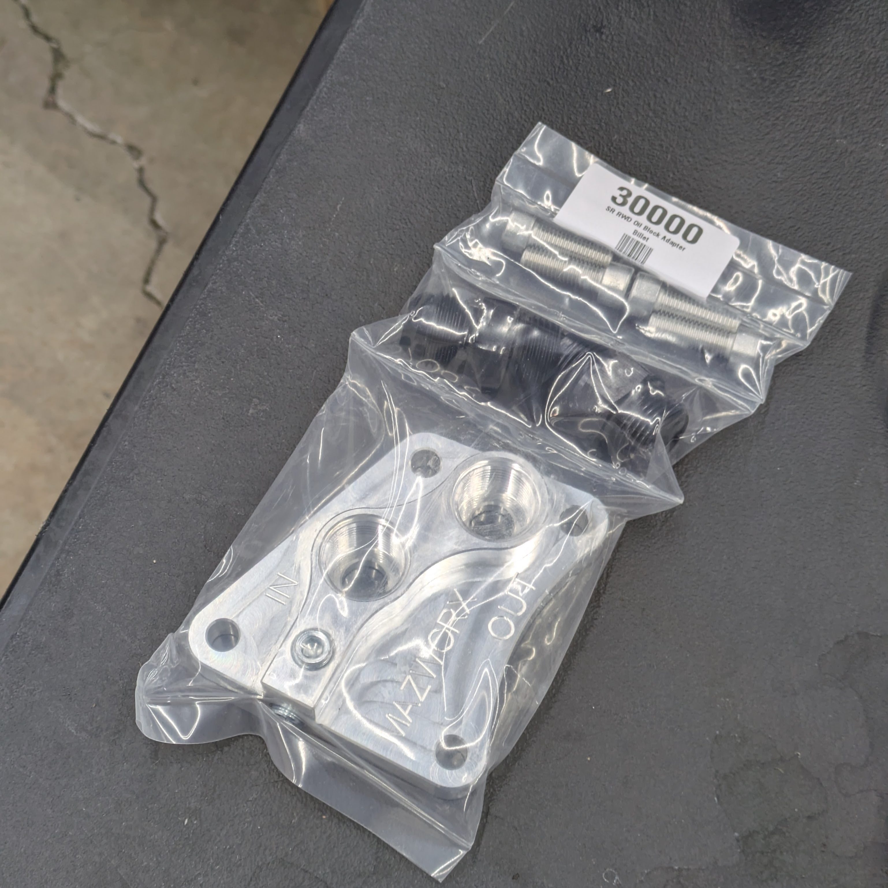
These two products were the star of the show when it came to exhaust side assembly. Obviously, the turbo is pretty much new, but I wanted the plumbing and hardware to be dialed so I didn’t have to touch it again.
The Jim Wolf Technologies stud kit is exactly what I would have assembled from scratch, but comes packaged in a kit. Yes, they are still in business, and yes, you still have to order over the phone, which I kind of love. This kit is awesome because Inconel studs can be pretty difficult to track down depending on length and pitch, and the stud material is critical, particularly between the turbo and the manifold, as insufficient heat tolerance or elastic properties will cause the studs to stretch and blow the gasket. The factory studs are inconel, and while mine were in good shape, I didn’t mind refreshing them. The nuts are also exactly what I wanted: copper nuts with distorted thread locking properties at the top, and no flange so that you can use locking plates.
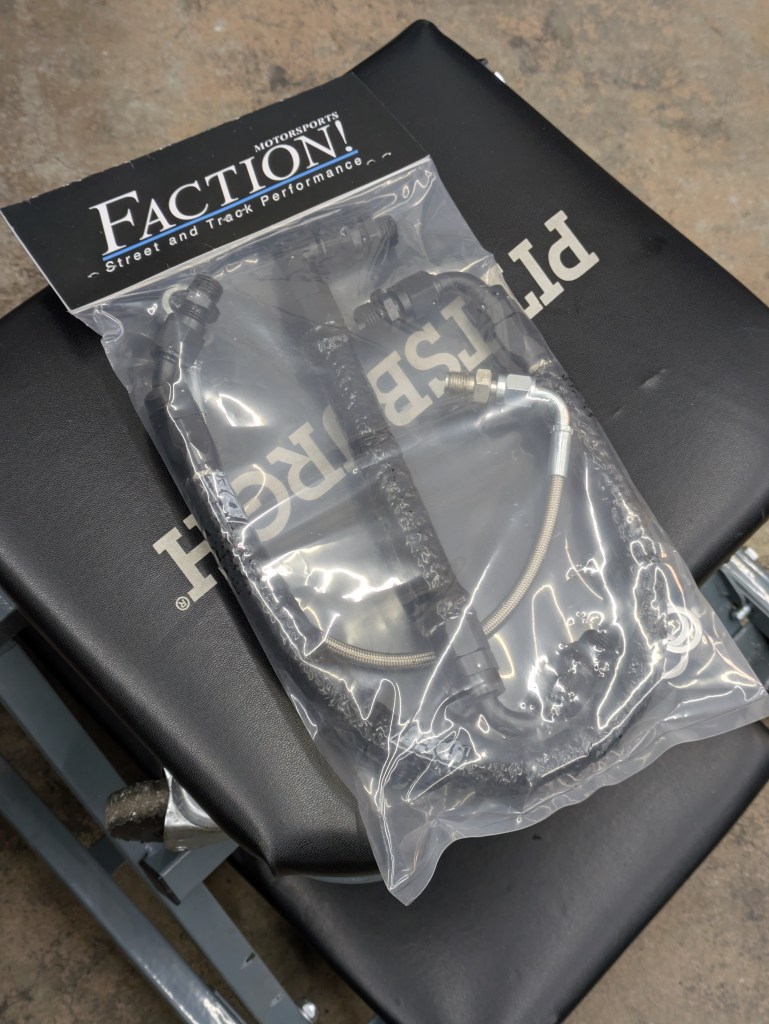
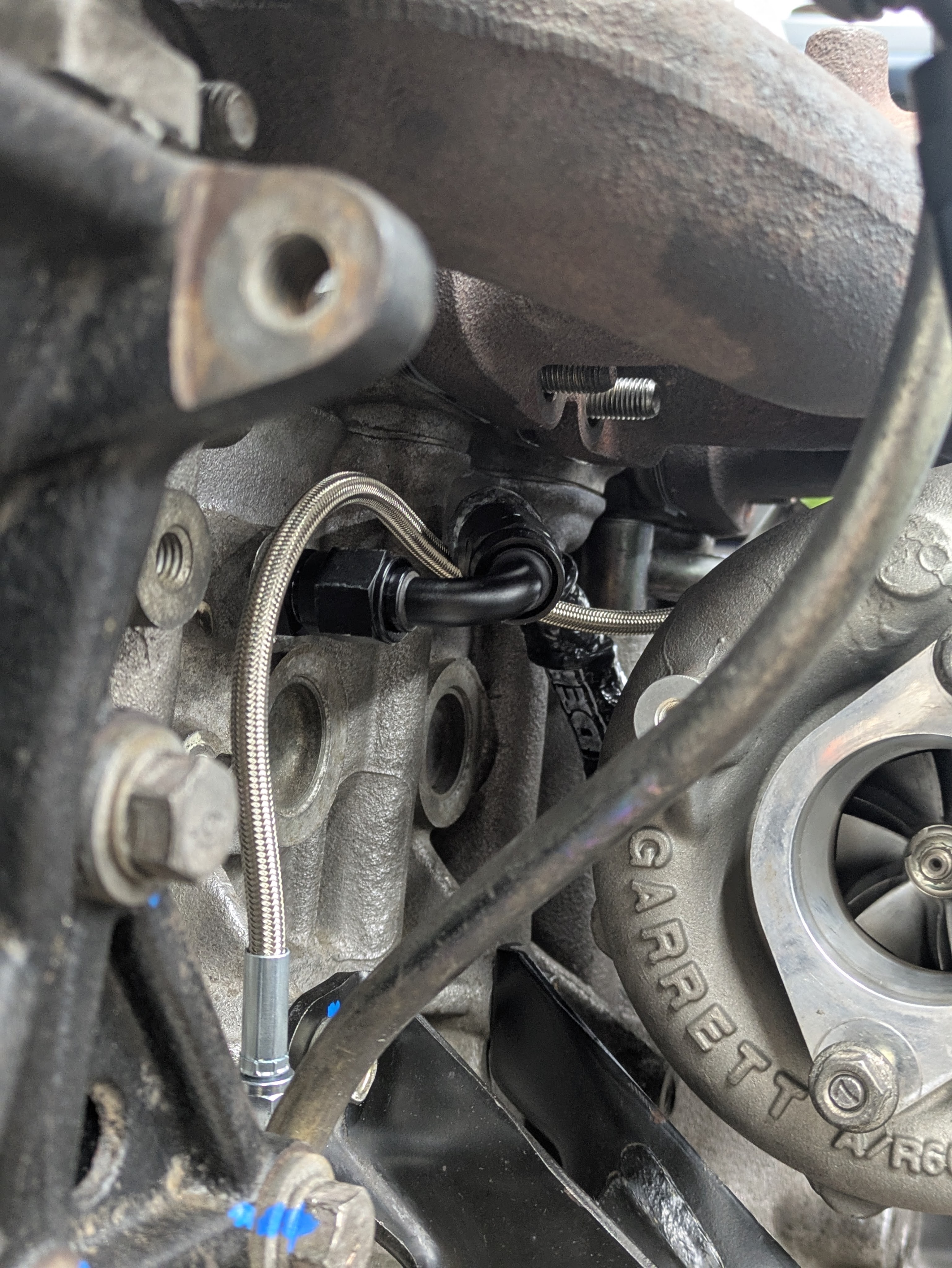
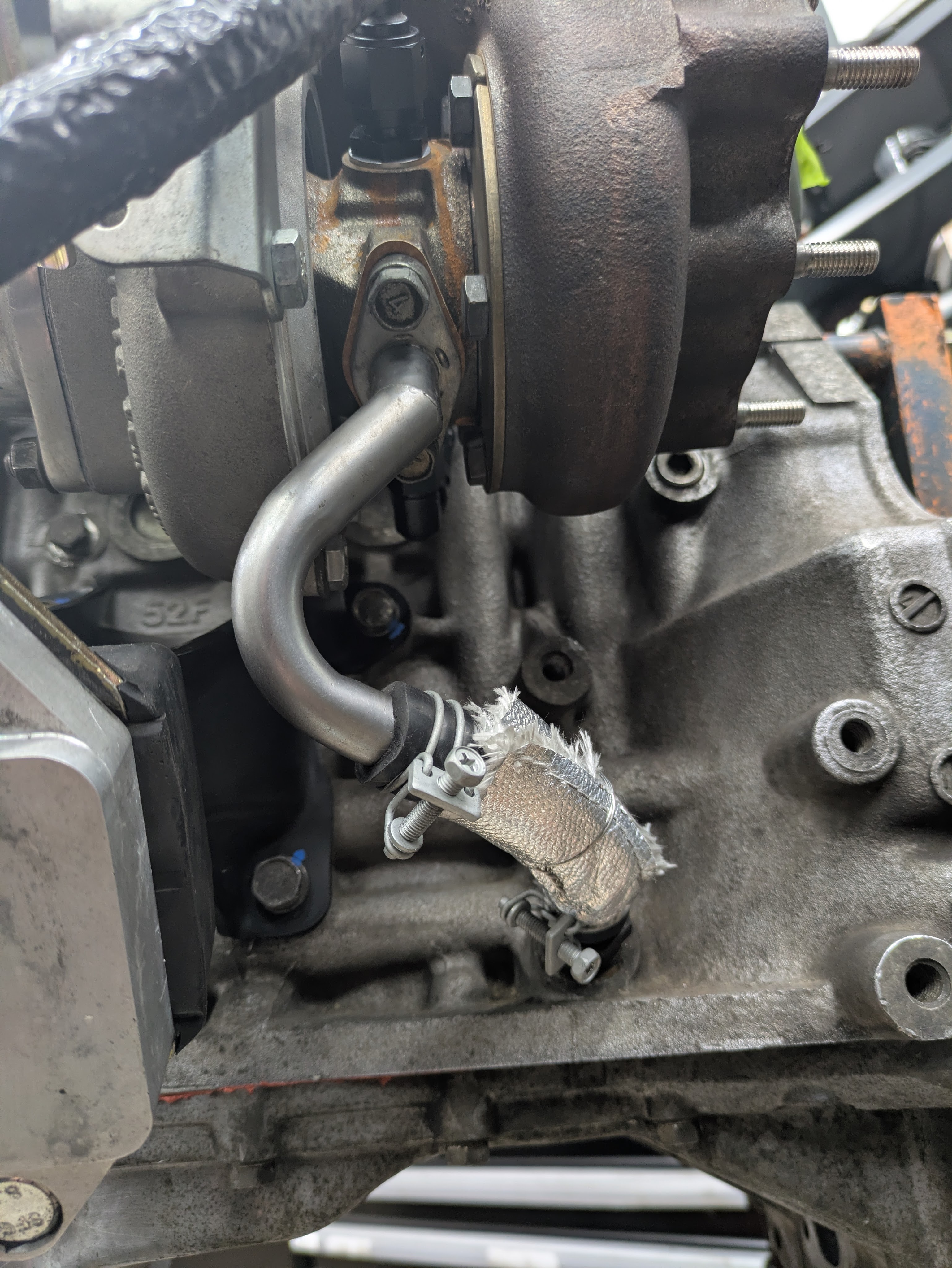
The Faction! Motorsports turbo line kit, while being the most expensive on the market, also had all the design criteria I wanted. Compact, routed cleanly and efficiently, heat sleeved, and inlet restricted for the ball bearing T28. It’s way easier to just show why they are great.
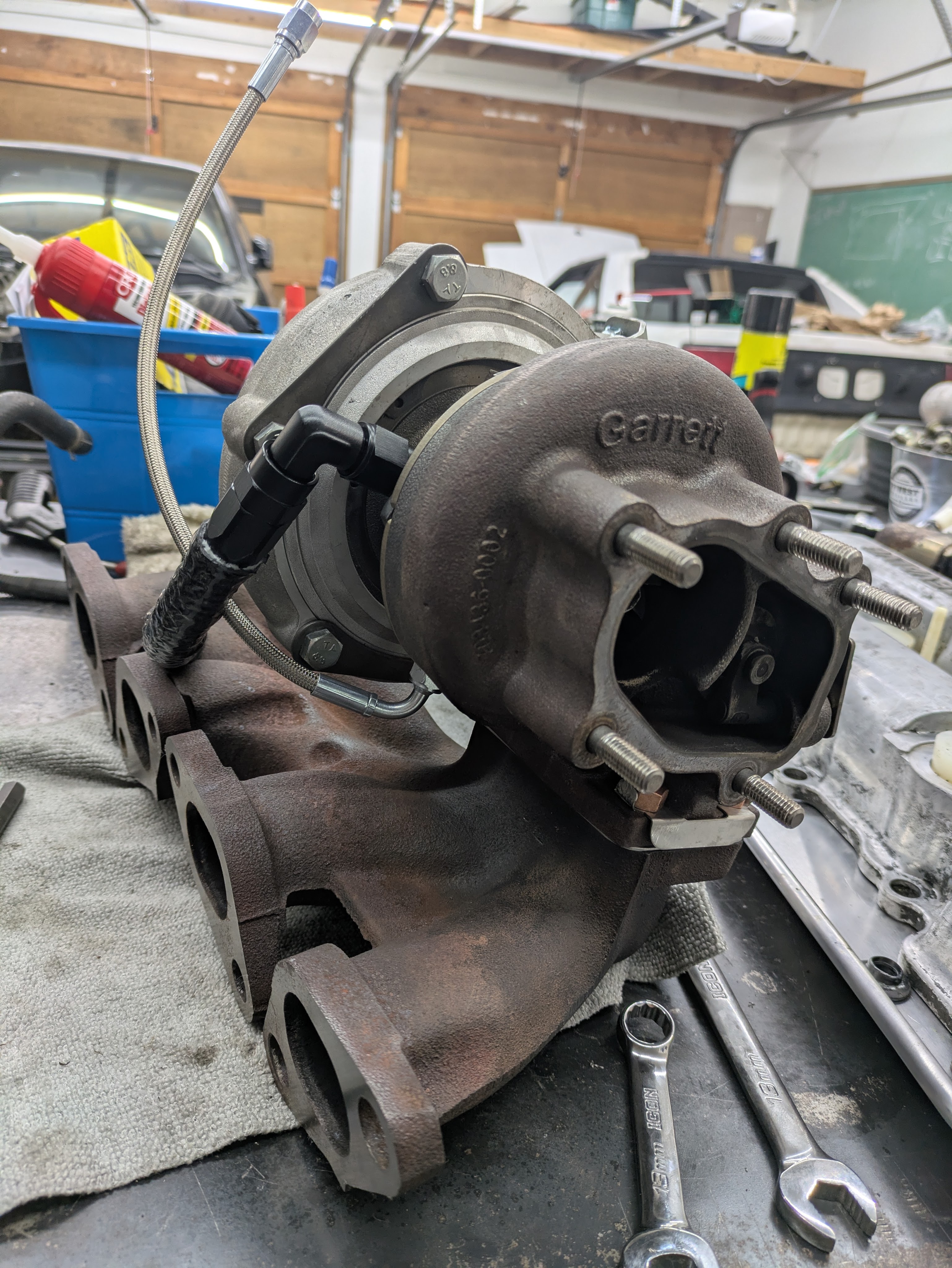
I got the studs installed into the manifold, and the turbo dropped on with a brand new gasket. I used GK Tech stainless locking plates. No complaints. They fit perfect and are cheap and available. I got the turbo fittings installed and tight so I didn’t have to worry about doing it when the manifold was on and the turbo was in the car.
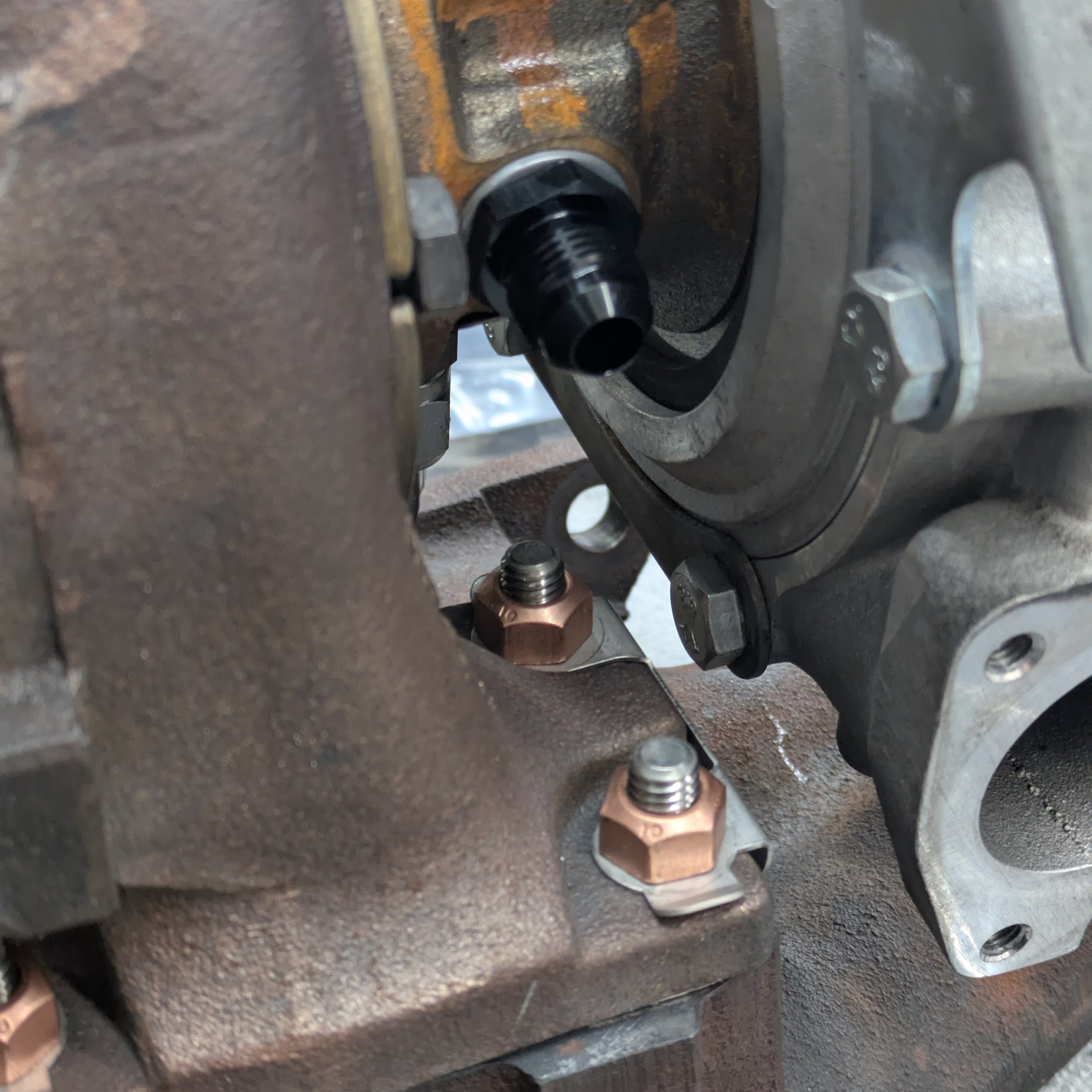
New Inconel outlet studs, torqued and staked nuts for the manifold outlet, and the inner turbo lines installed and managed. You can catch a glimpse of the resurfaced manifold as well. Really happy with this package.
All the time and money spent was worth it. Everything fit perfectly. The new hardware went on like a dream, and the lines fit exactly as designed.
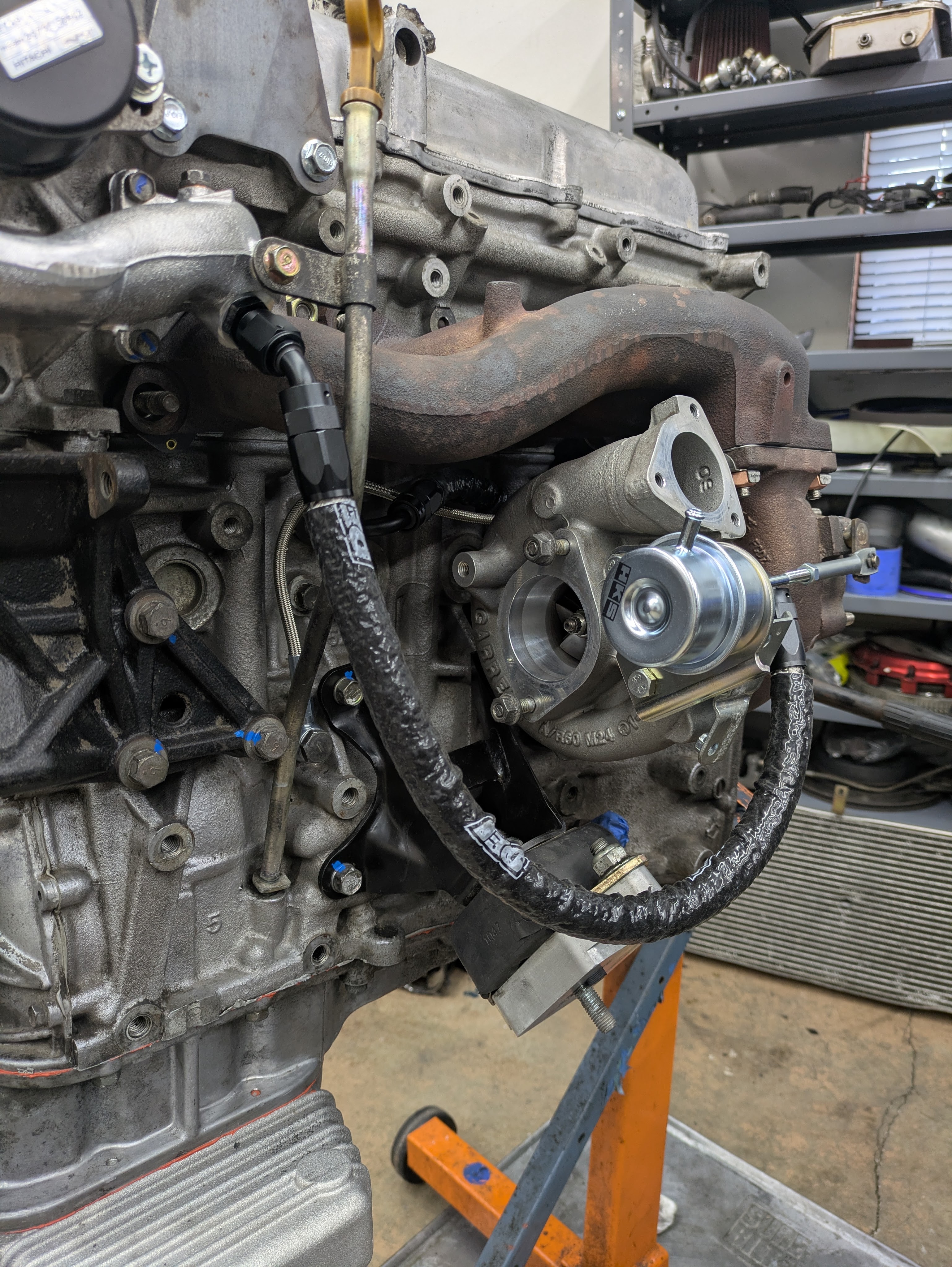
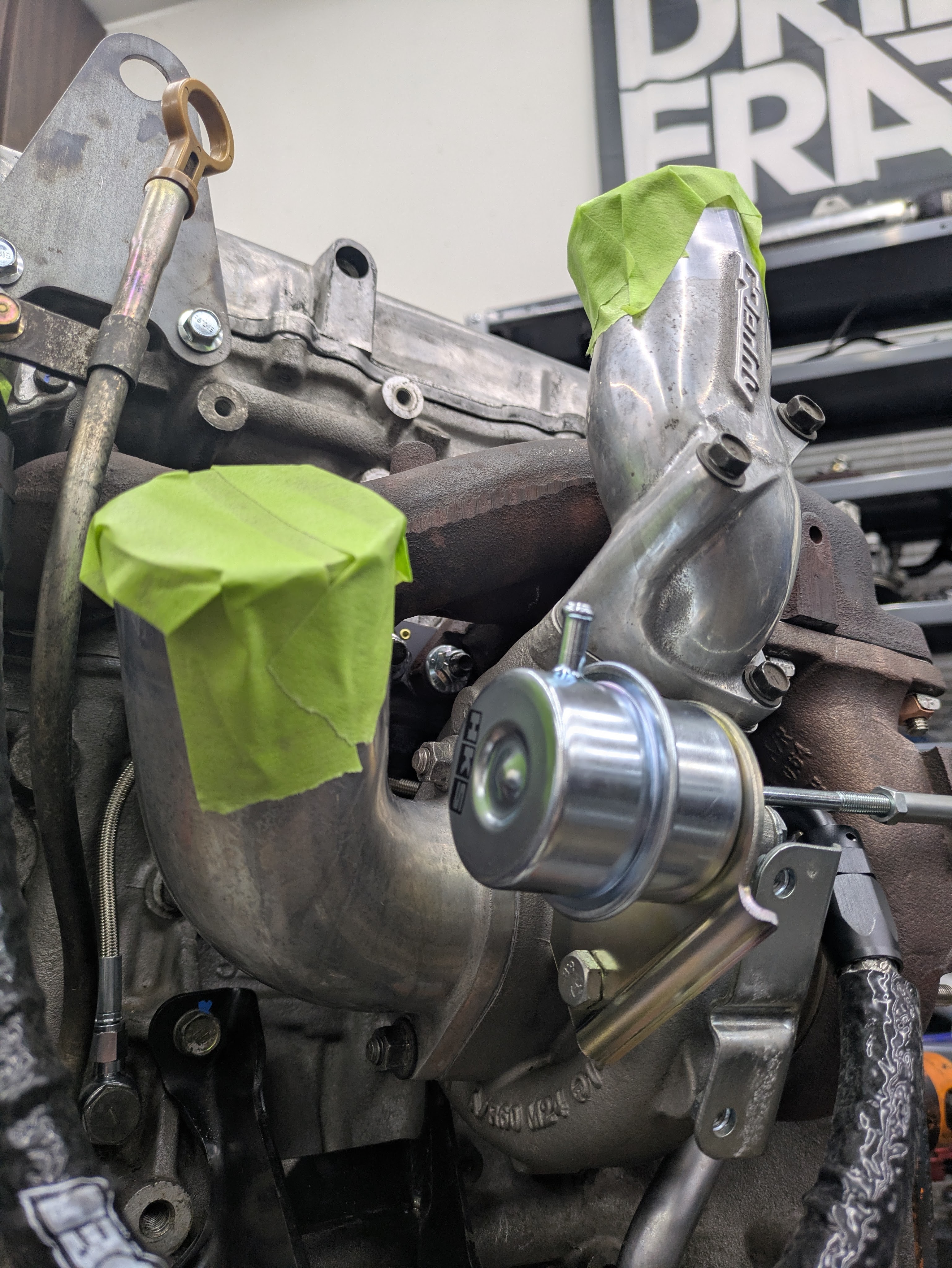
Three notable things from this image that aren’t related directly to previously discussed topics:
Oil pan(s) is on. Yes I used the heinous Nissan Red/Brown RTV. Came with my engine gasket kit + OEM never lets you down.
The very shiny HKS Turbo Wastegate Actuator is a welcome addition to the setup. This increases boost from the factory wastegate of 7-10ish lbs up to 0.9 bar, or just over 13psi. While I still intend to turn the car down to wastegate pressure for road racing, I wanted a bit more sauce than 10psi. My last motor had one, and it was great and they are cheap, so this motor got one too.
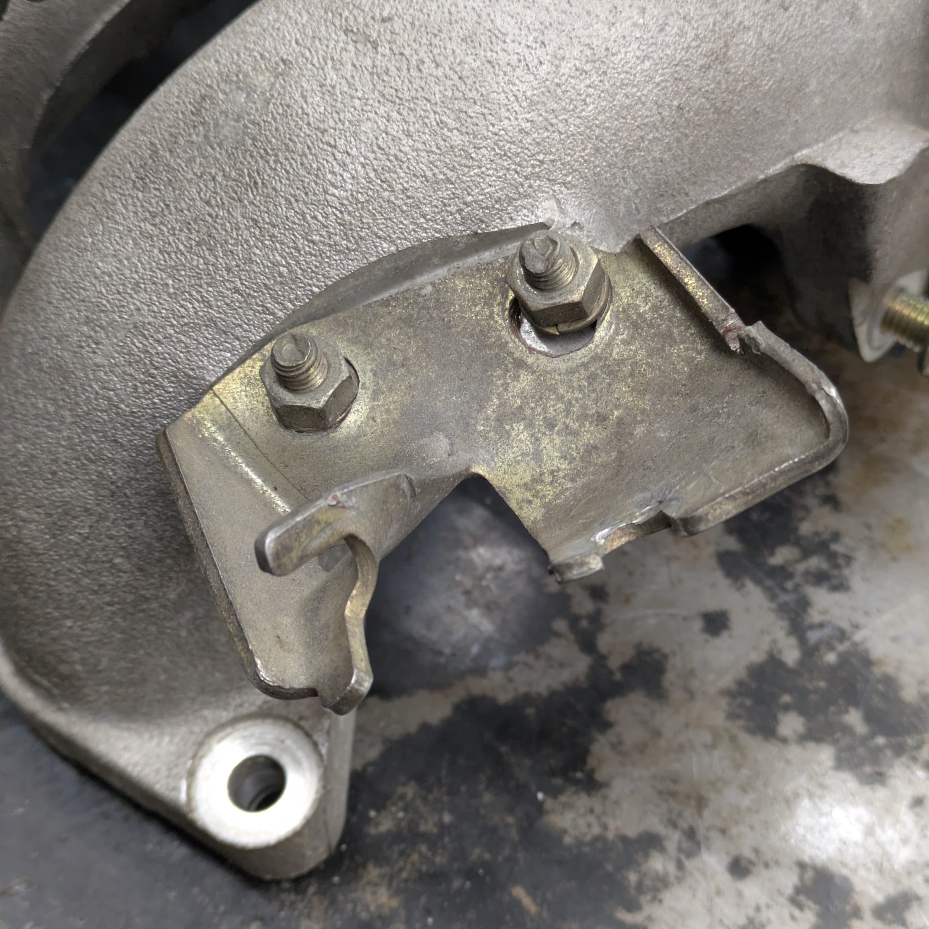
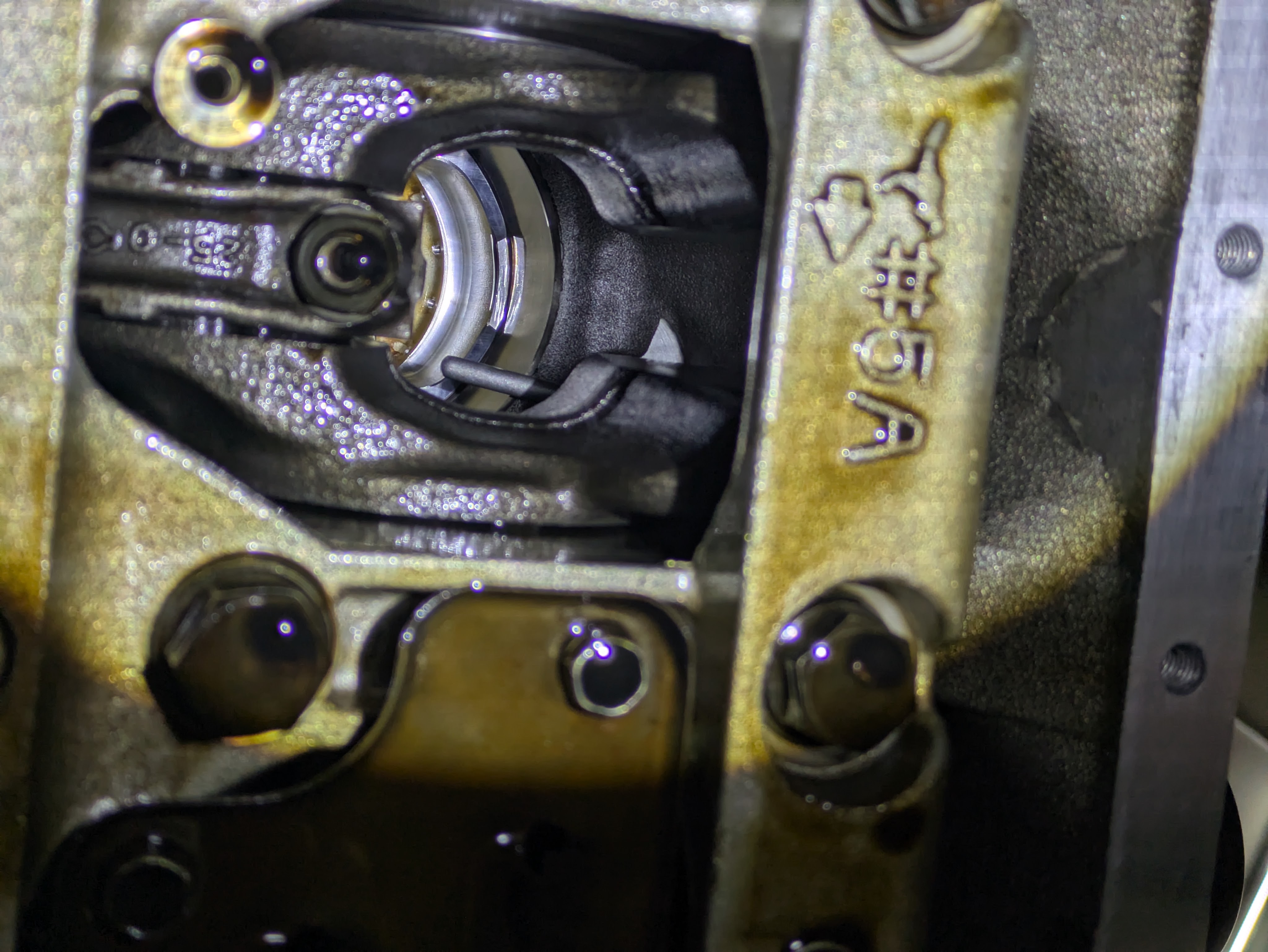
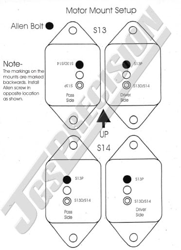
Finally: the engine mounts, seen installed on their brackets. These are another inclusion with the built motor that I am absolutely stoked about. These are made by a company called JGS out of Coos Bay, Oregon, and while discontinued, are legitimately the best S13 engine mount setup as long as you don’t want it hard mounted.
The sauce is all in the lower mounting puck, machined out of aluminum. It houses a bolt locked into a machined hex to act as the lower stud (so it’s replaceable if needed), and has a socket head cap screw acting as a dowell with adjustable locations depending on S13 or S14/15.
The other incredible thing is that the isolator part of the mount is a Jeep CJ5 mount, available literally everywhere for literal pennies. These have been used in the hot rodding scene for years, and for good reason. They are built well, easy to design around (2 bolt mounting location), a great height, available in many materials, and dirt cheap. Like literally $9 on Rockauto for a rubber one, or $35 for a polyurethane one. The cool part is the ability to stagger materials depending on use. I have a poly one on the turbo side that will get real hot and also has tension applied to it, but a rubber on the intake side to minimize vibrations on the street. With the rising cost of the Nismo mounts, these are superior in every way other than clout.
Alright, enough soapboxing about engine mounts and stock turbos. Put the motor together bozo. Going to rapid fire caption this as it’s more visual than textual.
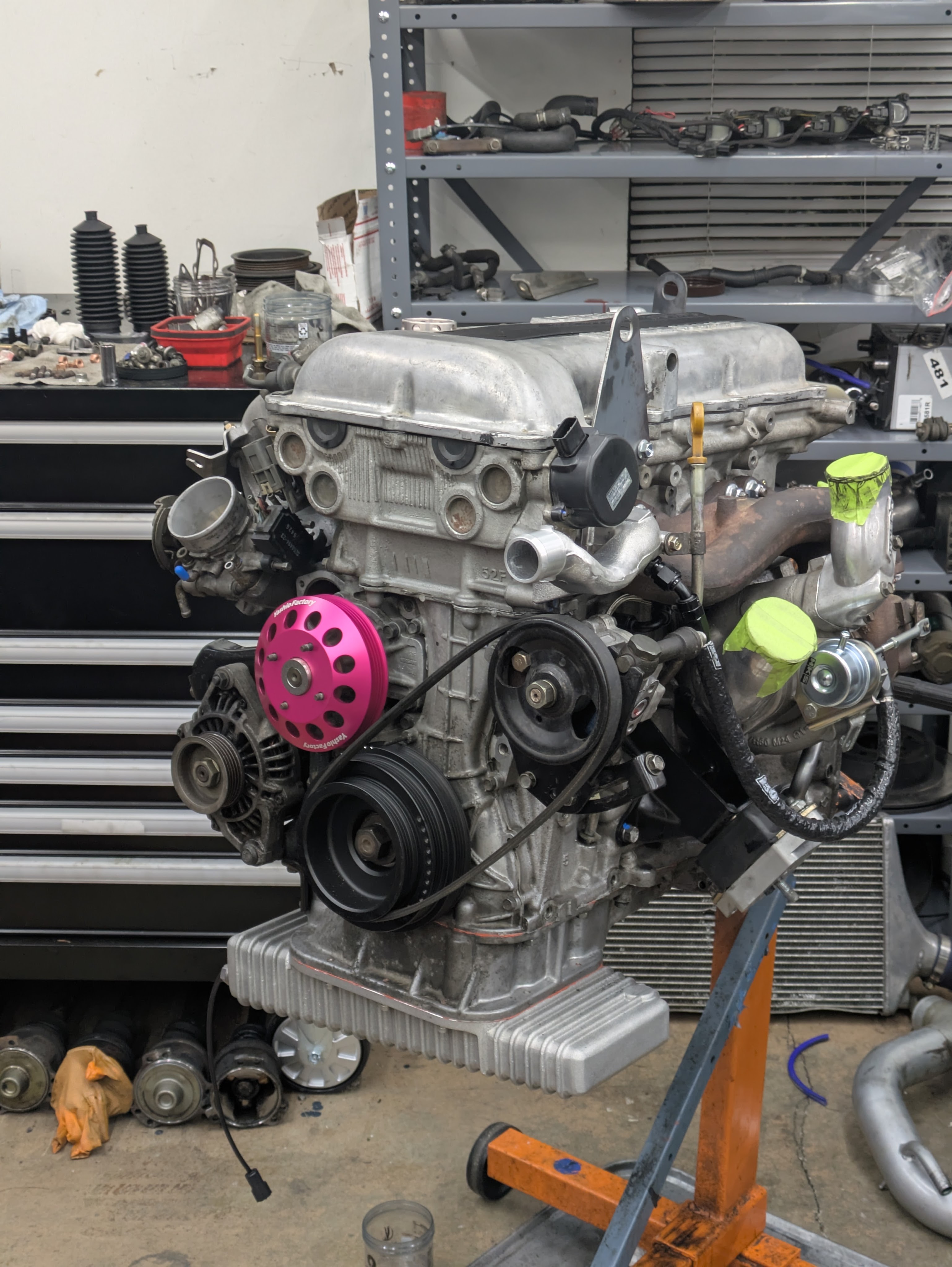
A final look at the complete motor. I ended up replacing the harmonic balancer as the old one had some cracking in the rubber isolator due to age. Front main seal was done at the same time since I already had it from the gasket kit.
The goal wasn’t to make it the internet’s standard “INSANE TRANSFORMATION” clean. While vapor honing and zinc plating is the aspiration that many strive towards, I find it to be an infinitely deep hole. As soon as you make something perfect, your eye then highlights the nearby imperfections. This motor isn’t free of that; The water neck, oil pan, and other brand new bits stand out a bit. While you can eventually irradiate those flaws with enough time and money, you are then sweating bullets scratching it or working on it in a less-than-ideal wrenching scenario.
I’ve found my niche to be clean original finishes. Its the cheapest to achieve with some sweat equity, and it’s maintainable. I know I can keep this motor looking like this forever, and I am content with that. If I don’t get dirty working on it, and it looks at home in the clean but unrestored engine bay, I’m happy to put my name on it. It feels relatable, if that makes sense.
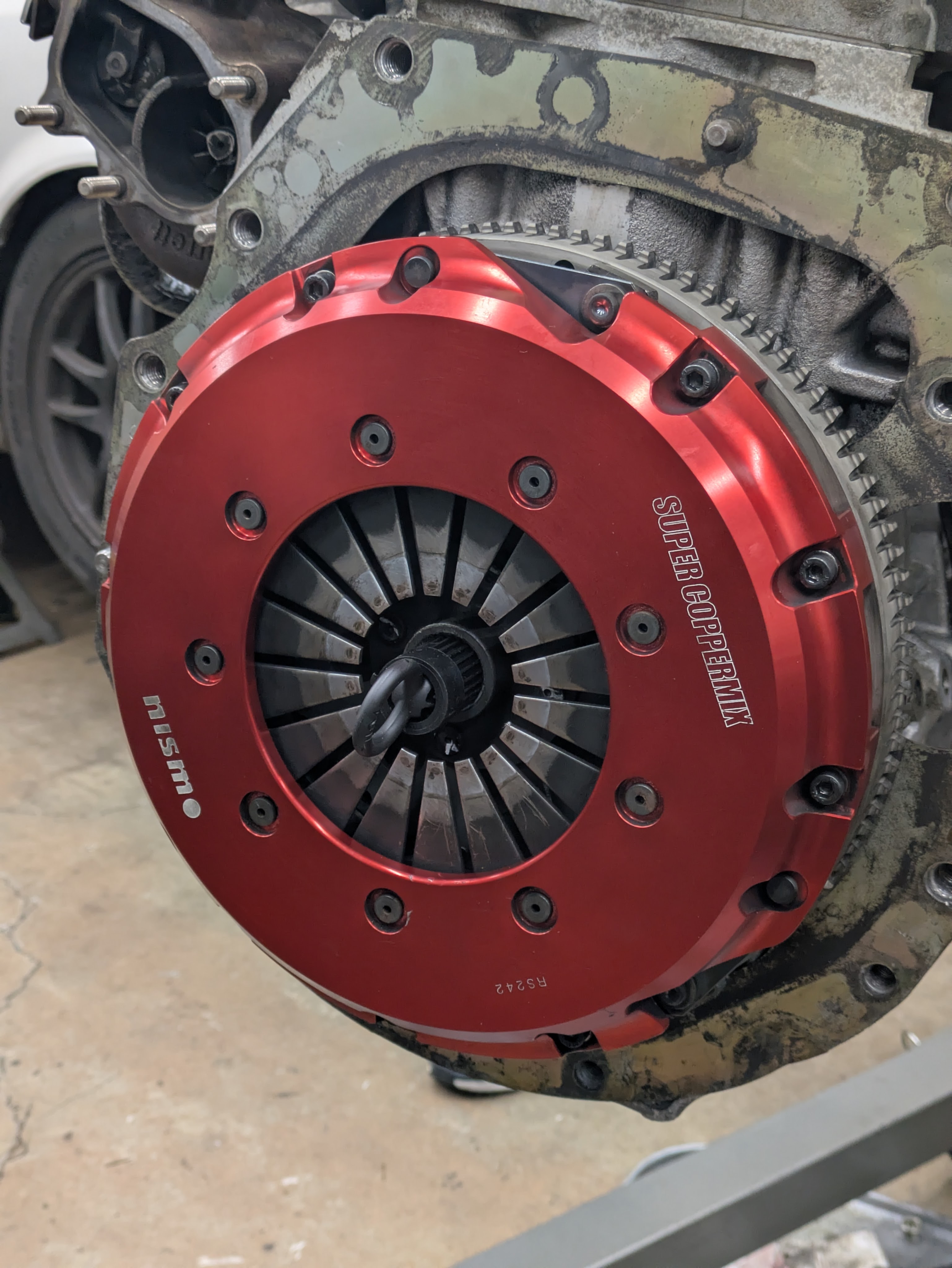
After completion, the engine sat ready to install for a few days before I finally had the goons (Nick and Aidan) and the gumption (barely existent yet still present) to finally get the install process started. The basically new Nismo Super Coppermix single plate clutch was included with my motor and and is a aesthetically and functionally exceptional piece. Everything this car needs and nothing more.
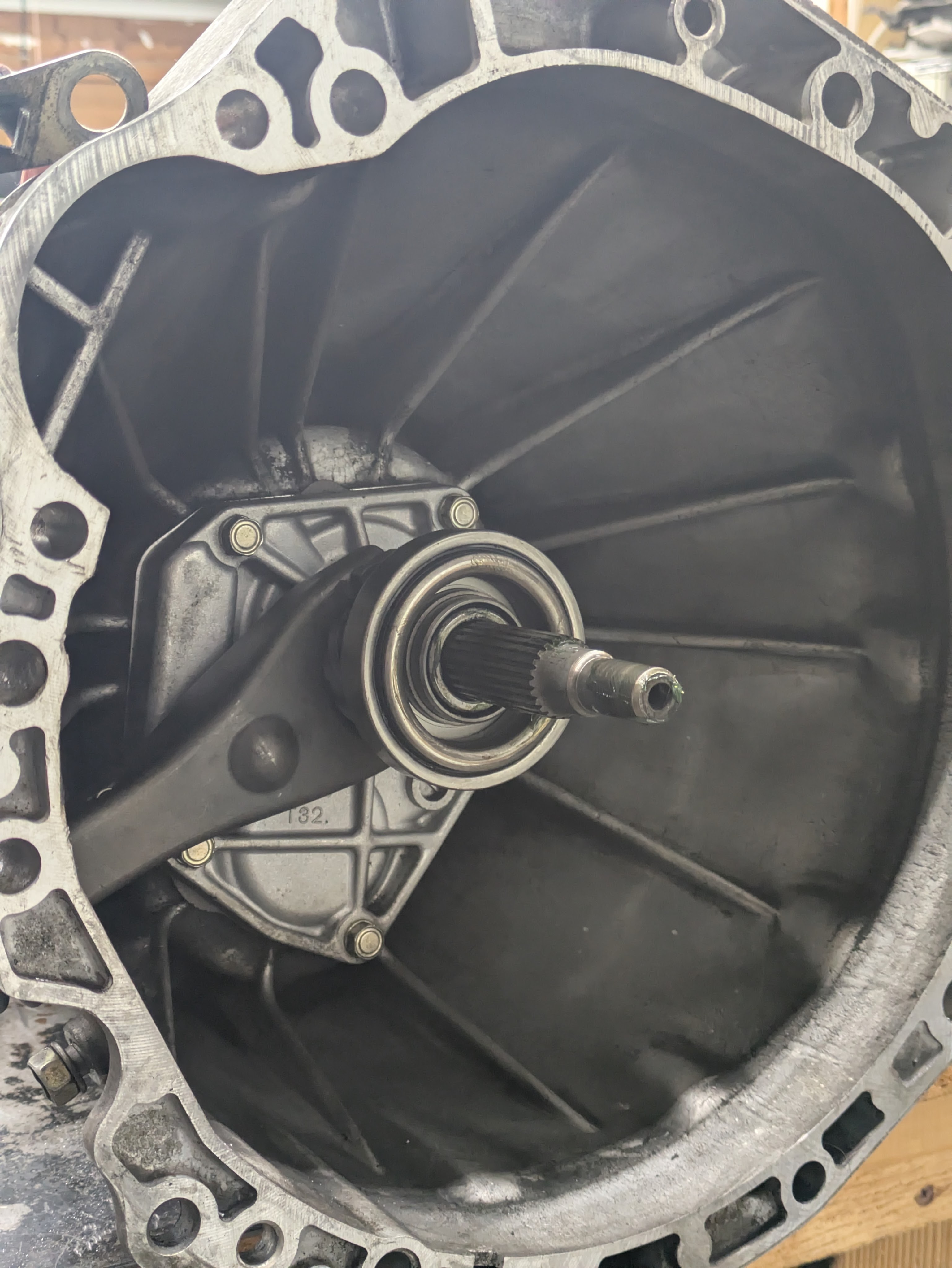
The transmission got the correct throwout bearing and a healthy coat of Honda Super Urea grease. While I had only been in there a few months prior (and it still looked the part), it was worth the once over.
With that, it was time to reinstall the powertrain, and gain a few square feet of floorspace back in the garage. It was my birthday weekend, and after crackin’ a couple cold ones, the engine went back home.
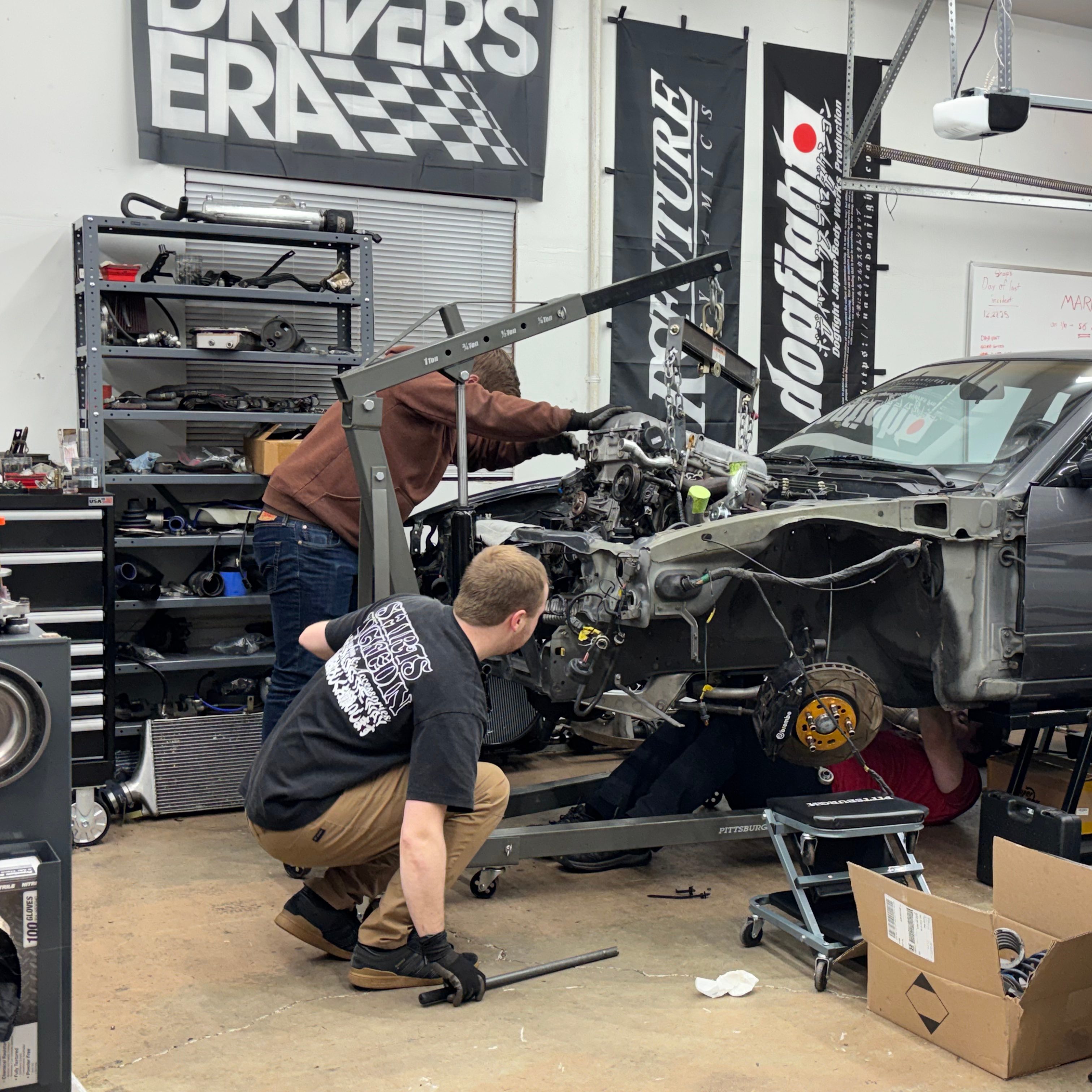
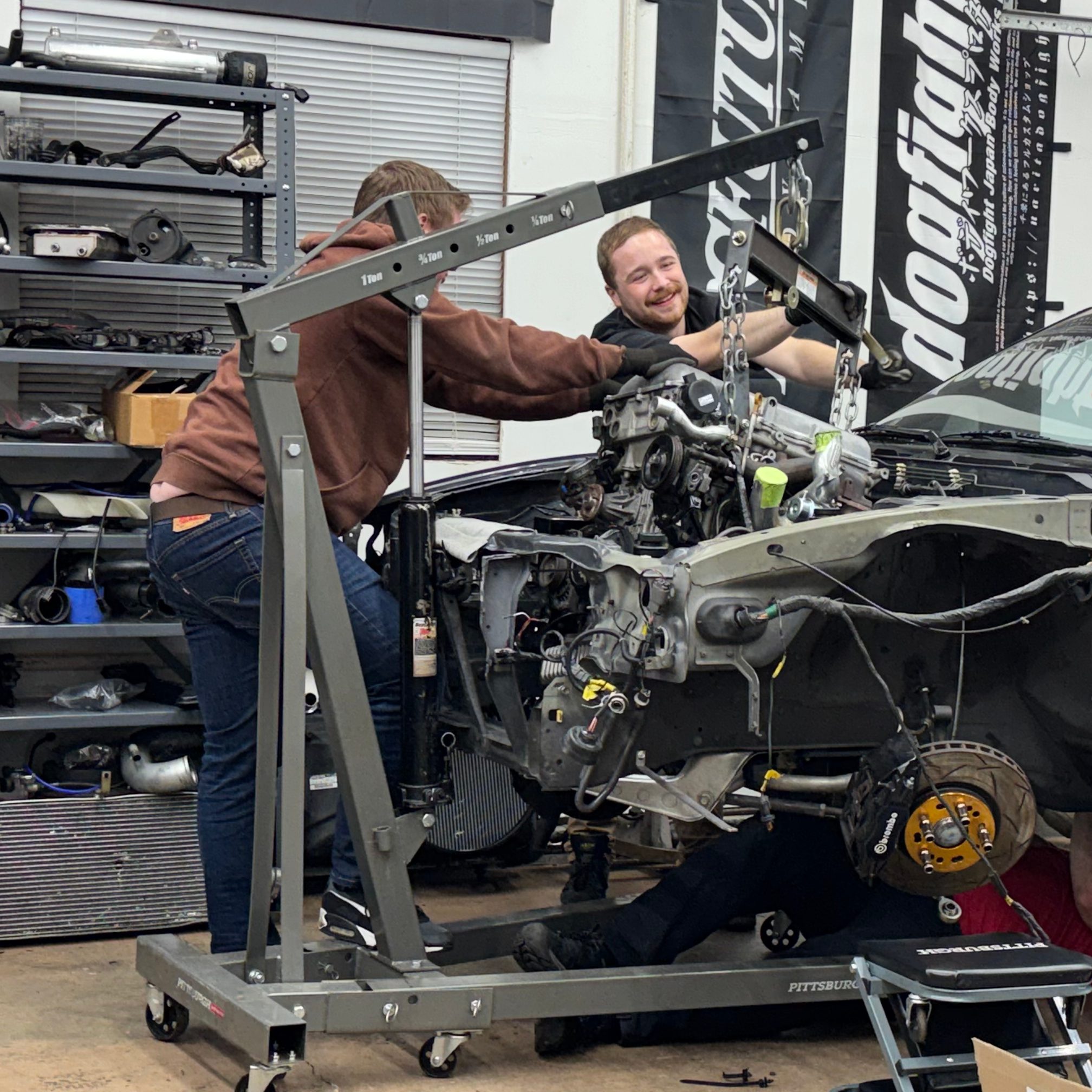
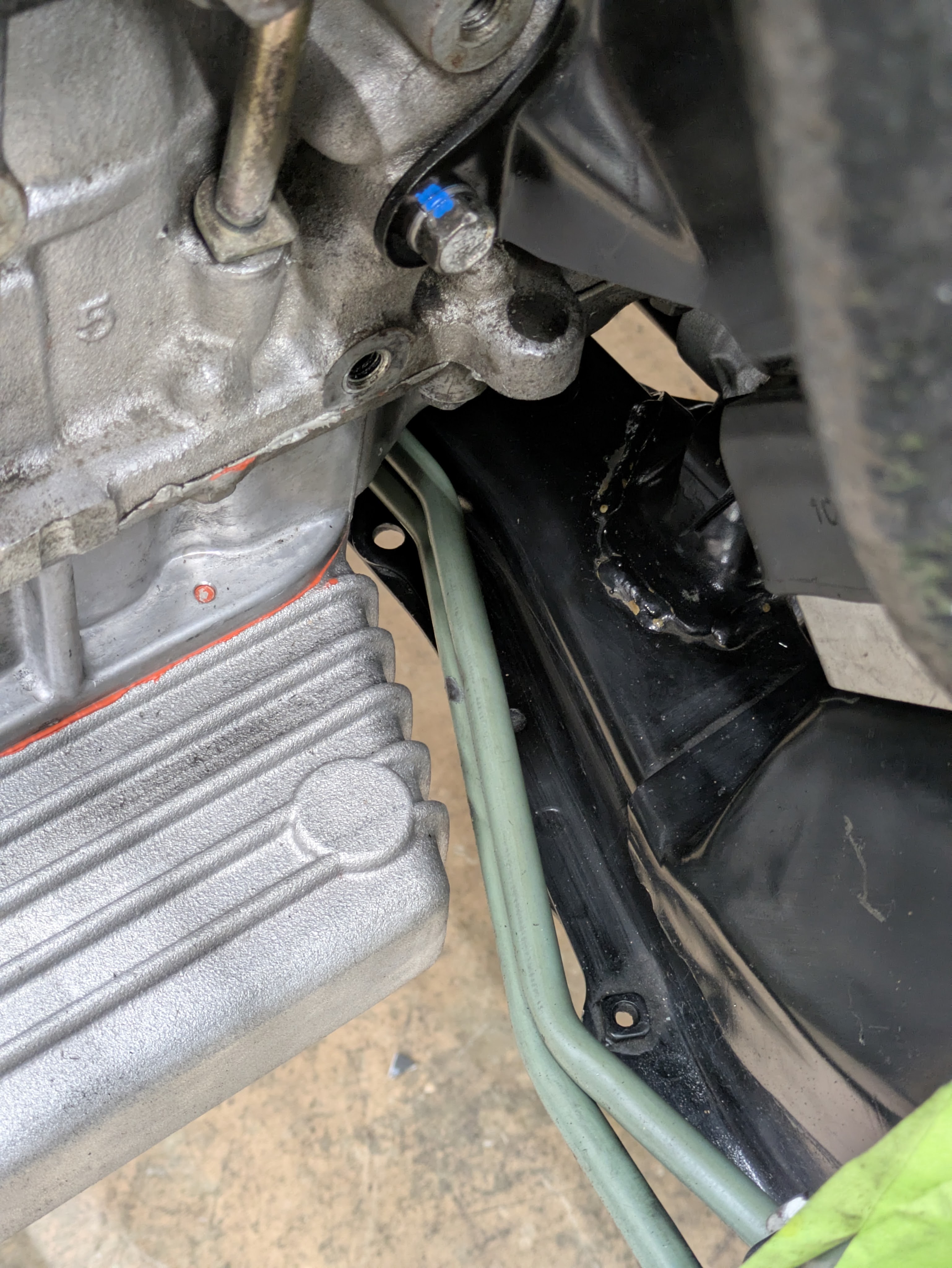
With those helping hands, the SR has landed back where it is supposed to be with no casualties north of a few subframe scratches from a few trips on and off the pedestals. The motor mounts needed some reconfiguring due to my own lack of education on them (I didn’t have that JGS config image until halfway through the install), but besides that, the motor install went very smoothly. Nothing better than some simple wrenching with the boys on my birthday weekend.
Everything fit perfectly after the motor mount adjustment, and I am exceptionally happy with the results. The oil pan is inline with the subframe height wise, the power steering hardlines clear everything, and it all bolts up exactly as it should.
While delayed in the release of the documentation, I can say that motor installation was a turning point in the progression of the car, and progress has not slowed down since. I have realized that my documentation speed has not matched the progression of the car, so there may begin to be a hefty delay between where the car is at in reality versus on the internet. Unfortunately, until someone pays me to write, I’m *slightly* more driven to drive my car rather than write about it.
So with that, updates may be delayed from here until completion, but know that there isn’t a day that goes by where I don’t do something to further the car. Is it mentally tormenting/exhausting? Yeah. But it distracts from the crappier parts of life, and I haven’t stopped being excited by it, so you could say I’m exactly where I want to be.
Until next time.
